Chapter 54 Methods for Cerebrospinal Fluid Diversion in Pediatric Hydrocephalus
From Shunt to Scope
Introduction
Definition and Epidemiology of Hydrocephalus
Hydrocephalus is one of the more common neurologic sequelae following insult to the central nervous system. It can be congenital or acquired. The incidence of congenital hydrocephalus has been estimated to be 0.48 cases per 1000 live births,1 whereas the incidence of neonatal hydrocephalus is 3 to 5 cases per 1000 live births.2 Table 54-1 lists common causes of pediatric hydrocephalus.3 Acquired causes of hydrocephalus include postintraventricular hemorrhage hydrocephalus, brain tumors, infections, and head injury.3 An estimated 33,000 shunts are placed in patients of all ages annually in the United States, with an estimated shunt prevalence of more than 56,000 in children younger than 18 years.4 In the United States, shunt placement accounts for 38,200 to 39,900 hospital admissions and 3.1% of all pediatric hospital charges ($1.4 billion to $2.0 billion).5 Hydrocephalus has not been clearly defined but represents a disparity between production and absorption of cerebrospinal fluid (CSF), resulting in raised intracranial pressure with or without ventricular dilatation.
Table 54-1 Common Causes of Hydrocephalus in 344 Pediatric Patients3
| Cause | Patients |
|---|---|
| Intraventricular hemorrhage | 24.1% |
| Myelomeningocele | 21.2% |
| Tumor | 9.0% |
| Aqueduct stenosis | 7.0% |
| CSF infection | 5.2% |
| Head injury | 1.5% |
| Other | 11.3% |
| Unknown | 11.0% |
| Two or more causes | 8.7% |
| Total patients | 99.0% (344) |
Clinical and Radiologic Features
The diagnosis of hydrocephalus is based on clinical features, radiologic appearances, and occasionally invasive intracranial pressure recordings. As seen in Table 54-2,3 children most commonly present with symptoms of irritability, delayed development, and vomiting. For infants, examination often reveals an increasing head circumference and a bulging fontanelle. Seizures are an uncommon presentation. Papilledema, when present, is highly suggestive of raised intracranial pressure. Papilledema is not particularly sensitive for acute raised intracranial pressure but is specific. If seen, it is highly suggestive of raised intracranial pressure; however, it has been shown to be absent in 86% of patient with shunt blockage.6 Sixth nerve palsy or loss of upward gaze may be a false localizing sign indicative of raised intracranial pressure.
Table 54-2 Presenting Clinical Features of Hydrocephalus in Pediatric Patients3
| Symptoms | Children |
|---|---|
| Irritability | 26.6% |
| Delayed developmental milestone | 19.8% |
| Nausea or vomiting | 19.0% |
| Headache | 17.5% |
| Lethargy | 17.5% |
| New seizures or change in seizure pattern | 6.6% |
| Diplopia | 5.8% |
| Worsening school performance | 4.2% |
| Fever | 2.6% |
| Signs | Infants |
| Increasing head circumference | 81.3% |
| Bulging fontanelle | 70.6% |
| Delayed developmental milestones | 20.9% |
| Loss of upward gaze | 15.8% |
| Decreased level of consciousness | 12.6% |
| Other focal neurologic deficit | 12.4% |
| Papilledema | 12.0% |
| Sixth nerve palsy | 4.6% |
| Hemiparesis | 3.8% |
| Nuchal rigidity | 1.8% |
Imaging that is commonly used in the primary assessment of a child with suspected hydrocephalus includes ultrasound, computed tomography (CT), and magnetic resonance imaging (MRI). The aim of imaging is to assist in the diagnosis and the etiology of hydrocephalus. MRI provides superior resolution to other imaging modalities and thus is useful when assessing the etiology of hydrocephalus. In addition, T2-weighted sequences such as fast imaging employing steady-state acquisition (FIESTA) and time-spatial labeling inversion pulse sequences7 provide information of fluid movement within the ventricles.
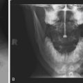
The risk of radiation from CT has prompted increased interest in limited-sequence or “quick” MRI.8 When evaluating patients with potential shunt dysfunction, brain imaging in conjunction with radiographs of the shunt tubing, known as a shunt series, should be obtained. A shunt series consists of two views of the head, neck, chest, and abdomen so that the whole shunt system is imaged. The current ventricular size in a patient with a possible shunt blockage based on contemporary imaging is not necessarily a good indicator of shunt blockage. Comparison to a previous scan when the patient was well with the same valve in place is far more reliable in terms of diagnosis of shunt blockage.
Physiology and Pathophysiology of CSF Circulation
• CSF radionuclide cisternography and MRI have not shown flow of CSF through the arachnoid granulations.9
• There is growing evidence in animal models (and human cadavers) that the nasal lymphatics may be the primary absorptive mechanism at normal pressure.10
Recently, there has been a different approach to the pathology of hydrocephalus.9,11 The CSF can be seen as extracellular fluid. The choroid plexus is the driving force for circulating the CSF along the pathway described earlier, but the absorption and, to a lesser extent, the production occur in the subarachnoid spaces and Virchow-Robin spaces. Regional changes in capillary bed caliber and permeability may affect this absorptive mechanism. When an obstruction develops, be it at the level of the aqueduct, the fourth ventricle, or the arachnoid on the brain surface, the absorptive capacity is reduced; therefore, a higher hydrostatic pressure is required to reach equilibrium between absorption and production. More research is required to substantiate these theories.
Treatment with Cerebrospinal Shunts
History of Shunts
The history of hydrocephalus is a fascinating one and dates back to the dawn of civilization. A good summary of the history is presented by McCullough.12 Early 20th-century attempts at achieving closed ventricular drainage included gold, glass, silver, and rubber tubes, as well as catgut and linen threads passed from the ventricle to the subdural space.12–15 Similar techniques were used to connect the lumbar thecal sac to the peritoneum or renal pelvis.16–18 After attempts at third ventriculostomy by Dandy19 and by Mixter20 and choroid plexectomy by Dandy,21 shunts from the lateral ventricle to cisterna magna (Torkildsen shunts22) and shunts from the lumbar spine to the ureter came into more widespread use.
The treatment of hydrocephalus was revolutionized when Nulsen and Spitz23 reported in 1952 the successful use of a ventriculojugular shunt using a spring and stainless-steel ball valves. The two valves were housed in rubber intravenous tubing, which acted as a flushing device, and connected to polyethylene tubing at either end. Unfortunately, occlusion of the venous catheter by blood clot was a frequent problem.
Holter’s shunt was the first to use silicone, and he designed a multislit valve out of silicone for use in his son, who had developed hydrocephalus.24 About the same time, Pudenz25 concluded that silicone was the best material and designed two valves to use as ventriculoatrial (VA) shunts.
Surgical Technique: Initial Shunt Insertion
Principles
Once the decision to implant or revise a shunt is made, the surgeon should begin planning the procedure. Informed consent discussing the rationale for the procedure, the potential complications, and the potential outcome should be sought in a timely fashion prior to surgery. The surgeon should pick out the shunt hardware prior to surgery. The following are important patient factors to consider when planning:
1. The most appropriate site for insertion of the ventricular catheter. The scan should be inspected, and the most appropriate site should be determined. In general, most ventricular catheters are inserted via a parieto-occipital or frontal bur hole on either the right or the left side. The most appropriate choice out of these four sites is often related to the underlying pathology driving the hydrocephalus. For example, it would not be appropriate to insert a VP shunt into the contralateral side of a tumor causing mass effect and midline shift, because this may exacerbate the midline shift. For patients who have had a recent shunt infection, it is optimal to use an uninfected bur hole site.
2. The most appropriate site for insertion of the distal catheter. In general, the preferred location for the distal catheter is the peritoneum, followed by the pleura or right atrium. The latter two choices should only be entertained when there is clear evidence that use of the peritoneum is highly likely to result in malabsorption, infection, or abdominal content damage.
3. The most appropriate valve to implant. A valve is required to maintain one-way flow and prevent reflux. Avoiding overdrainage of CSF and gravity-dependent swings in intracranial pressure, the effects of which include low-pressure headache and subdural hematoma,26–28 may also be accomplished to some degree. The most appropriate valve depends on a number of factors, including the age of the patient, what valve was used previously, the symptoms the patient exhibits, the number of previous shunt revisions, and whether having flexibility in the opening pressure is important. A more detailed account of the types of valve and the evidence pertaining to outcome based on valve choice is given in the next section. In general, patients should have the same valve reinserted if there were no clinical or radiologic problems before shunt dysfunction. For new shunts, the age of the patient is important. Neonates and young infants with open fontanelles have relatively low intracranial pressure compared to patients with a closed fontanelle. Hence, the valve inserted should allow drainage at lower pressures. We tend to implant medium-pressure valves in older children. Variable pressure valves are reserved for patients with complex shunt problems in whom the likely optimal intraventricular pressure based on history, examination, and investigations remains unclear.
4. Inspection of the site of the insertion of the ventricular and peritoneal catheter, as well as the proposed peritoneal catheter trajectory. Specific issues to consider include the site of previous incisions (avoid tunneling under scar tissue), the quality of skin (patients with multiple shunt revisions with large amounts of scar tissue and patients who have undergone radiotherapy are likely to be at higher risk of wound complications), the skin thickness (very young children with thin skin may require a low-profile valve and reservoir), and the presence of other devices such as central venous catheters, gastrostomies, Mitrofanoff devices, pacemakers, and other implanted devices may impede safe tunneling. The underlying pathology may also affect the bur hole site.
5. Evidence of concurrent illness. It is preferable to avoid inserting a VP shunt in the presence of infection elsewhere. In critically ill patients, even if their illness has been attributed to shunt malfunction, it may be more appropriate to insert an external ventricular drain (EVD). This gives the clinician a means for intracranial pressure measurement, allows intracranial pressure modulation by altering CSF drainage, and eliminates uncertainty whether the newly inserted shunt has failed if the patient fails to improve neurologically.
6. Past shunt history in patients who require a VP shunt revision. It is important to know what valve and shunt tubing were inserted previously, what difficulties were faced intraoperatively, and whether redundant shunt tubing was left in place and why. The last operation note, previous scans, and discharge summaries are invaluable pieces of information.
7. Need for assistance. If there has been a past history of bowel surgery, difficulty entering the peritoneum, or adhesions, consideration of performing the procedure with the assistance of a general surgical colleague is important.
VP Shunts
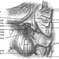
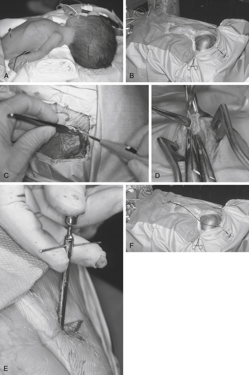
For a parieto-occipital VP shunt insertion, positioning is important. Once the patient is under general anesthesia and following administration of antibiotics on induction of anesthesia, we use the horseshoe headrest with a bolster placed under the shoulder ipsilateral to the ventricular catheter insertion site for positioning. The head is tilted such that the cranial incision site is accessible. This is usually achieved by rotation and lateral flexion of the neck to the contralateral side (Fig. 54-1A). This position is optimal for tunneling because it keeps the skin around the neck under some traction, provides a straight line from the cranial incision to the abdominal incision, and allows good access to the both abdominal and cranial incisions.
Many techniques have been described to determine the appropriate location for the bur hole.29 For example many people measure distances from either the ear or the midline to approximate the site of the bur hole. Whichever method is chosen, it is important to correlate the projected bur hole location with the optimal location on the preoperative imaging. Measurements made from CT scan are probably more accurate than choosing the site of the bur hole based on arbitrary surface landmarks. It is important to obtain localization in two planes. The use of neuronavigation removes all guesswork in localization of the optimal bur hole location but may increase cost and time. Furthermore, rigid cranial fixation is usually required, and this can hamper tunneling. Newer neuronavigation techniques such as electromagnetic-based systems eliminate the requirement for head fixation in pins, thus allowing easier tunneling.30
The skin is meticulously prepared with an antiseptic solution such as povidine–iodine or chlorhexidine. We use disposable, adhesive drapes to cover the patient and the operating table entirely, except for a small band of skin from the bur hole site to the abdomen (Fig. 54-1B). We use iodine-impregnated transparent adhesive drapes, although there is no evidence to suggest that shunt infection rates are reduced with this technique.
During the “time out,” we ensure that an appropriate dose of prophylactic antibiotics has been administered to achieve desired tissue concentrations and that we are operating on the correct patient, are operating on the correct side, and have the scans and equipment available. We do not infiltrate the wound with local anesthetic mixed with adrenaline, because this has the potential to increase the number of punctures of the skin and reduce blood supply to the wound. We use a horseshoe incision (Fig. 54-1C) that has its pedicle based on the direction the shunt will initially be tunneled. It is important to keep this pedicle wide and large so that no shunt equipment lies under the incision and blood supply to the flap is not restricted. For frontal bur holes, this may mean an obliquely oriented pedicle.
The size of the bur hole should be adequate to insert the ventricular catheter. We insert all our ventricular catheters under direct, real-time ultrasound guidance so that the bur hole required is quite large and allows access to the probe and the ventricular catheter simultaneously.31 In infants, particularly if premature, an opening between the splayed sutures at either frontal or occipital sites is often all that is required for dural access. A small dural incision just large enough to allow passage of the ventricular catheter is optimal, because this may reduce the risk of CSF extravasation into the subgaleal space. This is especially true in patients with thinned cortical mantle. The brain pia is cauterized and opened.
The abdominal incision is simultaneously opened by the second operator. There is no evidence that any specific location on the abdomen results in reduced complications. We avoid umbilical incisions because it is difficult to clean the umbilicus. The peritoneum should be approached by dissection in layers. It is vital to confirm that the peritoneum has been entered, for example, by observation of intraperitoneal contents such as bowel and liver, by flooding the field and watching fluid drain into the peritoneum, or by passing a blunt dissector into the abdominal cavity (Fig. 54-1D). The use of abdominal trocars to enter the peritoneum is a safe and acceptable technique, although we tend to ask our general surgical colleagues to assist when performing this maneuver (Fig. 54-1E).
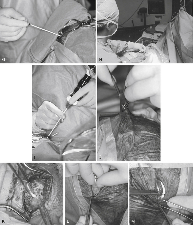
Tunneling is a potentially dangerous maneuver. The aim is to ensure the tunneling device is subcutaneous throughout its course. There is no evidence that the direction of tunneling, be it cranial to caudal or caudal to cranial, affects complications. A preassembled valve and tubing may not pass in the direction required because you have tunneled in an incorrect direction; hence, planning is important. Potential errant entries while tunneling include the skin, the peritoneum and its contents, the pleural space and lung, the heart and the great vessels of the neck, and the skull base, including the foramen magnum. As a rule, the tip of the trocar should be palpable below the skin at all times and the tip should pass superficial to the ribs and the clavicle. A common site of resistance to tunneling is at the deep cervical fascia of the neck (Fig. 54-1F). If you feel excessive force is required to pass the tunneler, a separate incision should be made and retunneling should commence from that location. If passing to a frontal bur hole, an intervening incision is usually required behind the ear. When tunneling along the chest wall, especially in neonates, there is potential to affect ventilation. The anesthetist should be made aware when tunneling, and the time during which the tunneler is subcutaneous should be kept to a minimum. The peritoneal tubing, with the attached valve, is then passed along the tube, attaching suction to the distal end and irrigating. The valve should then be irrigated to fill it with fluid. It is important to connect the valve in the correct direction (according to manufacturer’s instructions). We make a subcutaneous pocket to seat the valve (Fig. 54-1J).
The ventricular catheter trajectory is then determined according to external landmarks or using some form of image guidance, be it ultrasound or neuronavigation (Fig. 54-1G and H). From a frontal bur hole, traditional landmarks for the foramen of Monro are the intersection of the planes through the midline and just anterior to the external auditory meatus (or simply perpendicular to the skull). If the patient’s head is tilted, these landmarks can be difficult to appreciate, so palpable electrocardiogram electrodes placed at these points prior to draping may be of assistance. From the occipital location, a target at the midpoint of the forehead just at the normal hairline ensures that the catheter proceeds into the frontal horn instead of the temporal horn. For frontal bur holes it is generally accepted that the optimal position of the ventricular catheter tip is just anterior to the foramen of Monro, whereas for occipital bur holes the optimal position is the atrium of the lateral ventricle. In both cases, it is optimal to have the tip of the catheter away from the ventricular walls or choroid plexus. Endoscopic insertion allows visualization of the ventricular catheter in real time (Fig. 54-1I).
The ventricular catheter is then connected to the valve and ties are placed along any connections (Fig. 54-1K and M). The valve system is then positioned into the subcutaneous pocket that had been created (Fig. 54-1L). Once in place, the peritoneal catheter should be checked for spontaneous CSF flow. The surgeon should not close until it is clear that the shunt is working. If there is any doubt, the system should be disconnected to verify that both ends are patent.
Skin closure is critical. Any CSF leak predisposes to wound breakdown or infection. The rate of shunt infection has been shown to be as high as 57.1% in the presence of perioperative CSF leakage.32 We place an occlusive dressing on the wounds, particularly on young children, who may irritate or pick at their incisions.
Positioning in the postoperative period can be important. Premature infants may be particularly prone to skin ulceration if positioned with the full weight of the head on the valve hardware. In patients with large ventricles, early ambulation may predispose the patient to a subdural hemorrhage. In patients with high-resistance valves, placing them in an upright posture may promote CSF drainage and prevent accumulation under the skin. We allow patients to eat on completion of their surgery and clearance of anesthetics.
The postoperative hospital stay is typically 2 to 3 days. Intravenous prophylactic antibiotics are normally given preoperatively and sometimes postoperatively for two doses only. Shunted patients typically have rapid resolution of acute symptoms. In infants, a sunken fontanelle with standard valves is typical. Low-pressure headache can occur in older patients, particularly if the hydrocephalus is long-standing. Low-pressure headaches can be managed with bed rest, hydration, and simple analgesia. A postoperative scan is important to obtain as a baseline; however, the timing is up to the individual surgeon. Some evidence shows the ventricles do not reach their final size on average until 1 year of age.33 We tend to scan immediately postoperatively, after 1 year, and then approximately every 5 years in asymptomatic patients.
Ventriculopleural Shunts
A small pneumothorax is usually seen postoperatively on chest x-ray. It resolves over the next few days, whereas the CSF usually accumulates as a small pleural effusion. These patients must be monitored for any evidence of respiratory distress, with serial chest films and continuous oxygen saturation monitoring.34,35 Usually, the intrapleural fluid disappears over the next several weeks. In patients in whom the pleural fluid progressively accumulates, leading to respiratory distress with significant shift of the mediastinum, percutaneous drainage of the fluid and accessing another site for the tubing are required.
VA Shunts
The percutaneous method involves cannulating the subclavian vein under color flow Doppler ultrasound guidance. A Seldinger wire is then passed into the vein and progressed to the entrance to the right atrium. A dilator expands the entrance to the subclavian vein. Following this, a peel-away ventricular catheter is inserted. Under fluoroscopic guidance, the tip of the catheter is positioned just above the right atrium.36 The atrial catheter is then connected with a straight connector to the distal catheter, and all incisions are closed in two layers.
Other Sites of Insertion
Other options include reinsertion into the peritoneum, insertion into the gallbladder,37 insertion into the superior sagittal sinus retrograde to the direction of flow,38 and use of the vascular surgeons to assist in insertion into another peripheral vein. We have limited experience in any of these techniques.
Evidence-Based Approach to Complication Prediction and Avoidance During Shunt Surgery
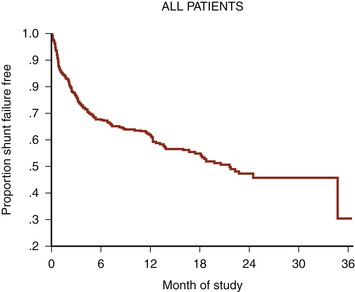
VP shunt surgery has a considerable long-term complication rate. The rate of shunt complications 1 month following insertion is 15%, rising to 25% after 1 year and reaching 34% after 5 years39 (Fig. 54-2). This figure does not appear to have improved with time.40 Failure rates in pediatric studies are even higher: 38% shunt failure rate at 1 year, going up to 48% at 2 years.41 By far, the two most common complications are shunt blockage and infection. Much of the neurosurgical literature pertaining to shunt complications relates to these two complications.
A number of factors affect the shunt complication rate. These have been categorized as follows:
The following sections discuss these three issues in greater depth, highlighting the current evidence on shunt-related complications.
Hardware Issues
The primary components of a VP shunt include a ventricular catheter, a valve, and a distal catheter.
Valve Selection
There are many shunt valves available on the market.42 They can broadly be categorized into either pressure- or flow-regulated systems. Pressure-regulated valves are either open or closed to CSF flow, depending on the pressure across them (Fig. 54-3A and B). Pressure-regulated valves can be grouped into four design categories:
• Slit valves, where slits within tubing open when the pressure is high enough. This type of valve is commonly used when inserting lumboperitoneal shunts, such as the Spetzler lumbar peritoneal shunt system (Integra NeuroSciences, Plainsboro, NJ).
• Miter valves, where two opposing leaflets are in the closed or open position depending on the pressure differential. Examples include the Mischler Dual chamber valve (Integra NeuroSciences) and the UltraVS cylindrical in-line valve system (Integra NeuroSciences).
• Diaphragm valves, where a mobile flexible membrane moves in response to pressure changes. Examples include the Heyer-Schulte Pudenz flushing valve (Integra NeuroSciences).
• Metallic spring ball valves,28 where a spring moves up and down depending on the pressure. Examples include the Miethke ProGrav valve (BBraun, Melsungen, Germany) and Polaris valve (Sophysa, Orsay Cedex, France).
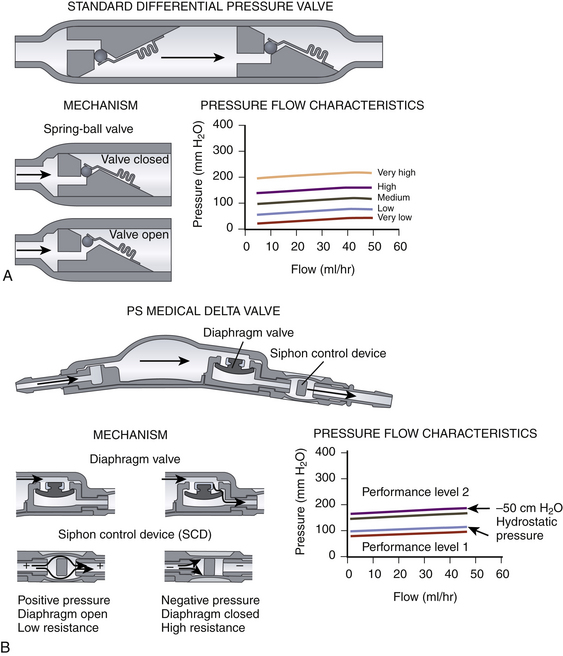
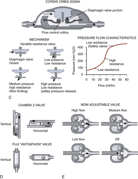
Flow-regulated valves work by reducing the caliber of the tube through which CSF flows when pressure increases but ensuring that some flow is maintained at all times.43 An example is the OSV II Orbis Sigma valve (Integra NeuroSciences) (Fig. 54-3C). This valve has a variable-diameter pin that partially occludes a ring whose position depends on the pressure. This alters the cross-sectional area through which CSF can flow. Thus, increased pressure would reduce the cross-sectional area; conversely, low pressure would increase it. The result is that, in an idealized system, the flow is constant irrespective of the pressure.
Measures to limit large changes in intracranial pressure based on the patient’s position include siphon-reducing devices. Antisiphon devices have a mobile membrane that moves to narrow an orifice in response to a negative pressure inside the shunt system when the patient is vertical (Fig. 54-3B).44,45 Examples are the antisiphon device and PS Medical Delta valve (Medtronic, Goleta, CA). Other valves try to reduce the effects of gravity by changing their configuration according to how they are positioned (Fig. 54-3D). In some designs, metallic balls rest on top of a standard spring ball valve to increase the opening pressure when the valve (and patient) is vertical. In another, a single metallic ball rests in an asymmetrical valve seat in upright position, increasing the resistance.
Does the Chosen Valve Affect Patient Outcome?
It is generally accepted that a valveless shunt with the diameter of tubing commonly available can cause siphoning, leading to intracranial hypotension with the attendant risk of subdural hematomas. However, there is some evidence that the use of a valveless system with a small internal diameter of tubing and a longer length of tubing may act as a flow-controlled system that prevents overdrainage.46 This mechanism by which overdrainage is prevented is similar to the mechanism by which a flow-regulated valve prevents overdrainage. This system exploits the Hagen-Poiseuille equation that states that the flow through a tube is inversely proportional to the radius of the tube,3 the length of the tubing, and the viscosity of the fluid.
There is much debate about the efficacy of flow-controlled valves compared to pressure-controlled valves. Kan et al.47 suggested that the incidence of slit ventricle syndrome (described in a later section) is lower in patients who have had a flow-controlled valve inserted compared to differential- and fixed-pressure valves; however, the diagnosis of slit ventricle syndrome was based on radiology, and clinical correlation was not performed. There is no compelling evidence that the shunt obstruction rate is related to whether a flow- or a pressure-controlled system is used.3
Ventricular and Distal Catheter Material Selection
The majority of shunt catheters are made from silicone rubber. During the manufacturing process, it is now possible to impregnate the catheter with other materials. The Codman Bactiseal catheter (DePuy) is a silicone rubber catheter impregnated with the antibiotics clindamycin and rifampin. Silver-impregnated polyurethane catheters (Silverline, Spiegelberg, Hamburg, Germany) are also available. In vitro testing of silver-impregnated catheters suggests that the silver prevents formation of bacterial colonies on the tubing, whereas antibiotic-impregnated catheters form a zone of inhibition of bacterial growth. It is thought that antibiotic-impregnated catheters prevent a bacterial biofilm from developing on the shunt tubing, thus preventing shunt infection.48
Does the Type of Catheter Affect Complications?
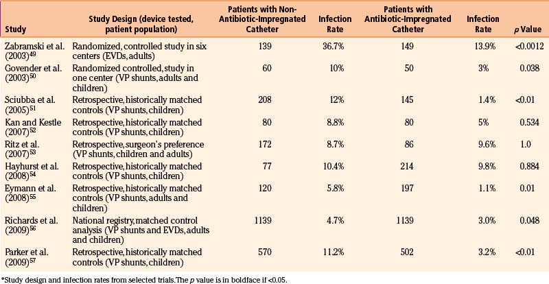
Numerous studies have investigated the efficacy of these catheters in prevention of infection. Table 54-3 lists many of the studies looking into the infection rate when different catheters are used. The results suggest that there may be a reduction in shunt infection rate when antibiotic-impregnated catheters are used; however, further studies are warranted to confirm this finding.
Patient Factors
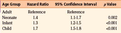
Age appears to be a strong predictor of shunt-related complications. Table 54-4 shows the hazard ratio of shunt-related complications based on age in a cohort of 19,284 patients of all ages. The incidence of shunt-related complications in children in this cohort was in the region of 48%, compared to 27% in adults.39 Tuli et al. also found age to be a significant factor in shunt failure.58
Table 54-4 Hazard Ratio for Shunt-Related Complications Based on Age on a Cohort of 19,284 Patients39
The underlying etiology of hydrocephalus is also an important predictor of shunt-related complications. Common causes of hydrocephalus in the pediatric population include aqueduct stenosis, Dandy-Walker malformations, obstruction by tumor, postintraventricular hemorrhage of prematurity, and hydrocephalus associated with myelomeningocele.59 Table 54-5 shows the incidence of shunt-related complications based on the condition warranting shunt insertion.
Table 54-5 Shunt-Related Complications Based on the Etiology5
| Condition | Shunt-Related Complication |
|---|---|
| Aqueduct stenosis | 6.7% |
| Myelomeningocele | 22.8% |
| Postintraventricular hemorrhage of prematurity | 13.6% |
| Posterior fossa tumor | 22.6% |
| Postinfection | 4.8% |
| Congenital condition | 10.8% |
| Post-trauma | 2.3% |
It has also been shown that the incidence of shunt failure is greater if multiple shunt revisions have been performed. Shunts are also more likely to fail within 6 months of implantation.33 The majority of patient risk factors for shunt failure are not alterable, so it is important for the surgeon to be aware of these risk factors when consenting patients.
Surgical Environment and Surgical Technique
The surgical environment has a great potential effect on the outcome of shunt surgery.
Surgeon and Surgical Experience
The number of shunt-related cases performed by the surgeon affects the incidence of complications. Smith et al.60 studied the in-hospital mortality rates for patients undergoing VP shunt insertion or revision in the United States between 1998 and 2000. They observed that high-volume institutions (more than 121 admissions per year) had a lower in-hospital mortality rate compared to low-volume institutions (fewer than 28 admissions per year).
A number of studies have looked into the seniority of the surgical staff. Cochrane and colleagues demonstrated that the surgeon’s experience significantly correlates to the survival of a VP shunt.5,61,62 The so-called July effect, looking at whether the start of new residents and fellows within a particular unit affects shunt complications, has also been reviewed. Kestle et al.63 showed a small detrimental effect in terms of shunt-related complications when new residents arrive to service.
Preoperative Prophylactic Antibiotics
There is some evidence that the routine use of perioperative antibiotic prophylaxis reduces the shunt infection rate. Haines and Walters64 performed a meta-analysis demonstrating a 50% reduction in shunt infection when antibiotic prophylaxis was used. There is no evidence on which antibiotic is most appropriate; however, most units have a local policy.
Skin Preparation
There is no evidence that any particular skin preparation results in a lower shunt infection rate; however, Darouiche et al.65 recently published a multicenter prospective, randomized, controlled study demonstrating reduced infection rates in clean, uncontaminated surgery (not including shunt surgery) when using chlorhexidine–alcohol compared to povidine–iodine.
Hair Shave
There is little evidence that shaving hair at the site of the procedure reduces infection rates.66–68 Our policy is to clip hair minimally at the site of incision and to ensure that hair does not enter the sterile field, thus avoiding hair becoming tangled within the wound when closing.
Double-Gloving
The use of two pairs of gloves or a new pair of gloves when handling shunt hardware has not been proved in the literature to reduce shunt infection.69 However, double-gloving is likely to reduce the incidence of glove perforations. Many surgeons elect to double-glove or change gloves, because this is an inexpensive maneuver that has the potential for reducing shunt infection.
Length and Position of the Ventricular Catheter
There is some evidence that the position of the ventricular catheter affects shunt survival. Tuli et al.33 demonstrated that a ventricular catheter surrounded by CSF on a postoperative image had a significantly lower risk of blockage compared to a catheter tip touching the brain or completely embedded in parenchyma. Many surgeons suggest that the optimal position for a ventricular catheter placed from a parieto-occipital bur hole is in the atrium of the lateral ventricle and placed from a frontal bur hole is just above and in front of the foramen of Monro; however, individual factors such as the ventricular morphology should be accounted for. The optimal length of the ventricular catheter for frontally placed shunts has been said to be in the region of 5 to 5.5 cm, whereas the length for occipitally placed shunts is 5.5 to 6 cm. Again, however, the ventricular anatomy based on preoperative imaging should dictate the length of the catheter. There is little evidence that the incidence of shunt blockage is different when comparing a frontal to a parietal insertion.70,71
The site of the incision and the trajectory for cannulation of the ventricle have historically been based on surface landmarks. More recently, neuronavigation techniques have been increasingly applied, especially in the context of the patient with small ventricles.72 Ultrasound is becoming more popular intraoperatively during shunt placement. Bur hole probes are commercially available, allowing for real-time insertion of ventricular catheters.31 We hope that image guidance will improve catheter placement and thus reduce the shunt failure rate.
Placement of the Distal Catheter
The peritoneum over the right atrium has been the preferred site for distal catheter placement for a number of years. Borgberg et al.73 demonstrated that the shunt revision rate was 51% for VA shunts, compared to 38.5% for VP shunts. Furthermore, the mortality rate of VA shunts has been quoted to be as high as 3%.74,75 Complications specific for VA shunts include right-sided heart failure, venous thrombosis, chronic septicemia and shunt infection, intraoperative air embolus, and cardiac arrhythmias.
Ventriculosubgaleal shunts have recently had a resurgence in the context of posthemorrhagic intraventricular hemorrhage of prematurity with associated hydrocephalus.76 Small studies suggest that the complication rate may be lower compared to the intermittent use of a ventricular access device.
Management of Shunt Complications
Shunt Blockage
No data demonstrate a reliable relationship between the duration of shunt blockage and the speed of clinical deterioration of the patient. Some patients may have clinical symptoms for long before becoming unwell, whereas other patients become unwell quickly. The Birmingham, Alabama, group has analyzed their experience of shunt-related death.77 Symptoms of raised intracranial pressure longer than 24 hours prior to death were present in at least 10 of the 28 patients who died. Of these, 5 patients had symptoms for 1 to 4 weeks. They also found that 8 patients died prior to arriving at the hospital. We find that, given that the duration of symptoms prior to a catastrophic event is variable in shunted patients, the safest approach is to review the patient as soon as possible. The Birmingham, Alabama, group’s follow-up study also emphasizes the importance of patient education to prevent such events.78
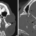
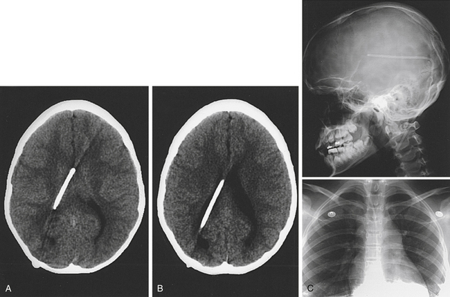
The diagnosis of shunt blockage is usually made on clinical evaluation combined with a CT/MRI scan and a shunt series (Fig. 54-4). Clinical history in a patient with shunt blockage may reveal symptoms suggestive of raised intracranial pressure. However, subtle deterioration in intellectual performance may be the only symptom of shunt dysfunction. Examination of the site of the shunt may provide some evidence of shunt dysfunction. Fluid around the ventricular site is indicative of proximal shunt blockage or of fracture/disconnection of the shunt apparatus, whereas fluid around the distal catheter and/or ascites is indicative of a CSF malabsorption process.
Although pumping of the shunt reservoir is a time-honored technique, this is often misleading.79 Shunts whose reservoirs remain depressed for a long time raise the possibility of proximal shunt obstruction. However, this may simply represent a small ventricular size. A reservoir that is difficult to depress or refills apparently instantaneously frequently indicates a distal obstruction. Some shunt reservoirs contain proximal and distal occluders. By occluding the distal reservoir and depressing and allowing the reservoir to refill, we can infer that the proximal catheter is patent. Similarly, by occluding the proximal reservoir and flushing distally, we can confirm patency of the distal catheter.
Another commonly used preoperative method of shunt interrogation is tapping of the reservoir. Placing a small gauge butterfly needle connected to a manometer provides an evaluation of the pressure required for CSF to flow distal to the reservoir. The valve is usually distal to the reservoir, so we are, in effect, interrogating the valve and the distal tubing. Evaluation of the proximal catheter is more difficult and subjective and requires gentle aspiration of CSF from the butterfly needle. If flow is “easy,” then the probability of a proximal shunt blockage is low. CSF can also be sent for microbiologic examination in the process. The risks of this bedside procedure include introducing infection.
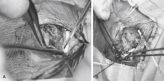
When operating on patients with shunt blockage, it is important to prepare and drape the abdomen, as well as the head, because the only definitive method for diagnosing shunt blockage is operation with the proximal catheter, valve, and distal catheter visible. For this reason, we usually open the cranial incision in the first instance. Careful dissection with the monopolar cautery onto the shunt tubing is an effective method for exposing the tubing without damage (Fig. 54-5A). The components are then systematically disconnected and interrogated. If there is no spontaneous flow from the proximal catheter, then a proximal blockage is diagnosed and the proximal catheter needs revision. It is preferable to remove the catheter and replace it with a new catheter. Often, especially when shunts have been in place for a long time, the ventricular catheter is quite stuck. The catheter should not be pulled out because this is likely to result in intraventricular hemorrhage. It may be possible to free the catheter by placing a stylet through the catheter and using the monopolar cautery to coagulate any choroid plexus occluding the holes at the tip while twisting the catheter (Fig. 54-5B). If this is not possible, the catheter should remain. If the ventricular catheter inadvertently slips into the ventricular system, an endoscopic approach is usually indicated to “fish” the catheter out. CSF should always be obtained and sent for microbiologic examination for all shunt procedures.
VP Shunt Infection
• Wound infection: an incision or shunt tract with signs of inflammation, purulent discharge, and organisms seen on Gram stain or culture. Wound breakdown with shunt tubing exposed should be treated as a shunt infection.
• Meningitis: fever, meningismus, CSF leukocytosis, and organisms seen on Gram stain or culture.
• Peritonitis: fever, abdominal tenderness (abdominal pseudocyst and abdominal abscess may present with mass with or without fever), and organisms seen on Gram stain or culture. For vascular shunts, findings are fever, leukocytosis, and positive blood culture, with or without evidence of shunt nephritis or cor pulmonale.
• Infected shunt apparatus: minimal signs of CSF contamination with bacteria recovered from purulent exudate in or on shunt material, Gram stain of CSF withdrawn from the shunt, or positive culture on fluid aspirated from the shunt under sterile conditions.80
The most common organisms infecting CSF shunts are staphylococci. Approximately 40% of shunt infections are caused by Staphylococcus epidermidis infections and 20% by S. aureus.81–83 Other species isolated from infected shunts include the coryneforms, streptococci, enterococci, aerobic gram-negative rods, and yeasts. Propionobacteria acnes is a relatively common organism causing shunt infection but requires prolonged culture to diagnose.84 We recommend anaerobic culture with prolonged incubation. Because these organisms are commonly part of the normal skin flora, and shunt infection usually occurs within 2 months of surgery, endogenous spread from the patient or surgical staff is the logical route of infection. Most surgeons would agree that a relatively early shunt infection (i.e., within 6 months of insertion) is seen as a surgical complication.
Bacteria colonize the shunt in the form of a continuous biofilm. This biofilm is composed of bacterial cells, either singly or in microcolonies, all embedded in an anionic matrix of bacterial exopolymers and trapped macromolecules.85 The biofilm offers protection against many common antibacterial agents, including antibodies, white blood cells, surfactants, and antibiotics. For this reason, treatment of shunt infections by the exclusive use of systemic or intraventricular antibiotics82,86 has been generally ineffective, although a recent report in patients without S. aureus infections had reasonable resolution if infections with intraventricular antibiotics were injected into a separate CSF reservoir.87
It has been shown that shunt removal with interval antibiotic treatment (usually with EVD) carries the highest shunt infection cure rate and the lowest mortality rate.88 CSF shunt removal with immediate replacement carries an almost equal shunt infection cure rate and a higher morbidity and mortality rate. Antibiotic treatment alone has the lowest cure rate and the highest mortality rate. Continuous discussion with the microbiology/infectious disease team members throughout treatment is important. They should advise on isolation of the organism, the appropriate antibiotic based on sensitivity testing, the duration of antibiotic treatment, and when it is appropriate to internalize the shunt. Intrathecal administration is commonly instituted in many units. It is important to ensure that the person administering the antibiotics has been appropriately trained.
Intra-abdominal Pathology
Contamination of the shunt can occur from other general surgical procedures,82 such as insertion of a gastrostomy with peritoneal shunts. If a patient presents with obvious peritoneal sepsis (e.g., ruptured appendicitis or perforated bowel), it is generally accepted practice to externalize the shunt by making an incision over the chest wall (i.e., distal to the valve) and connecting the catheter to an external ventricular drainage system. When performing this procedure, the level the drain should be placed at is 0 cm above the foramen of Monro because the valve will still be functioning. Reinternalization should be performed only when the intra-abdominal sepsis has been eradicated. If there is a high chance of bowel adhesions, it may be more prudent to convert to a ventriculopleural or VA shunt. When reinternalizing a distal catheter, it is important to retunnel from an area proximal to the exit site, usually the valve, and to use new catheter tubing. This approach can be applied for the unusual complication where the shunt migrates through the bowel wall and out through the anus.
Slit Ventricle Syndrome
A consequence of chronic overdrainage is slit ventricle syndrome. Nomenclature in the literature is confusing. Some authors define the condition as small ventricular size associated with symptoms of intermittent shunt blockage. When the ventricles are very small, the shunt blocks. As the ventricles expand, the shunt unblocks, thus creating a cycle of intermittent shunt blockage.89 A product is noncompliant ventricles. There are three theories as to the pathogenesis of noncompliant ventricles; however, it is likely that the true pathophysiology involves more than one mechanism. The first is that ventricular pressure is intimately related to intracranial venous pressure and when CSF pressure drops, uncoupling occurs. This leads to increased venous congestion and increases brain elasticity. The second is that increased pressure with subependymal flow can cause subependymal gliosis and periventricular gliosis with increased ventricular wall stiffness. If this happens, intraventricular pressure would need to be higher than usual to obtain ventricular dilatation. The third proposed mechanism is that low-pressure valves in neonates lead to overshunting with radiologic slit ventricles, the development of microcephaly, and synostosis. This in turn predisposes the ventricular catheter to obstruction and prevents the ventricles expanding in response to obstruction.
Comatose Patients with Fixed, Dilated Pupils
Patients presenting in coma are fortunately a rare occurrence; however, when seen, management must be prompt. A large bore spinal needle can be placed through the bur hole along the presumed trajectory of the ventricular catheter if the patient is in extremis. Patients presenting in coma should have an EVD inserted, rather than a shunt revision, because if the patient has a VP shunt revision and does not come out of coma immediately, it is difficult to ascertain whether the prolonged coma is caused by blockage of the new shunt or the neurologic damage from the initial presentation was so severe to keep the patient in a comatose condition.
Endoscopic Third Ventriculostomy
History
The earliest endoscopic treatment for hydrocephalus was choroid plexus fulguration performed by Lespinasse in 1910.91 Dandy92 subsequently described an open technique for third ventriculostomy for the treatment of noncommunicating hydrocephalus. A percutaneous ventriculostomy technique using an endoscope was first described by Mixter in 1923.20 Fay and Grant93 published the first intraventricular photographs that same year, providing the first visual record of endoscopic anatomy. Because of the limited illumination and large size of early endoscopes, open ventriculostomy procedures, as well as percutaneous fluoroscopic and later CT-guided techniques, remained popular for many years. Johns Hopkins provided the technical advances necessary for the revival of neuroendoscopy.94 Hopkins’ innovative solid-rod lens and coherent quartz fiber lens systems underlie the basic design of all modern rigid and flexible endoscopic systems. The improved optics and illumination and reduced size of modern endoscopes have greatly increased their utility and reduced their associated morbidity and mortality.
Patient Selection
ETV has been intended to treat noncommunicating hydrocephalus with patent subarachnoid spaces and adequate CSF absorption. Results of ETV have been related to the cause of hydrocephalus encountered, as well as clinical and radiographic features of the individual patient. Table 54-6 lists causes of obstructive hydrocephalus classified according to reported success rates of ETV (see the later section on outcome). Patients with acquired aqueductal stenosis or tumors obstructing third or fourth ventricular outflow have demonstrated the highest success rates, exceeding 75% in carefully selected series of patients.95–98 Previously shunted patients with or without myelomeningocele and patients with congenital aqueductal stenosis or cystic abnormalities leading to obstruction (i.e., arachnoid cyst or Dandy-Walker malformations) have shown intermediate responses.96,97,99–101 Infants presenting with hydrocephalus associated with myelomeningocele, hemorrhage or infection have generally demonstrated poor response to ventriculostomy,94,102,103 and despite limited reports of success in such patients,97,99,100,104–107 they have been more controversial candidates for this procedure. The procedure is not advisable in patients who have undergone prior radiation therapy because of the extremely poor response rates, altered anatomy (i.e., thickened third ventricular floor), and increased risk of bleeding.97,99,103
Table 54-6 Ventriculostomy Success Rates by Hydrocephalus Cause
| High Success Rates (≥75%) |
| Acquired aqueductal stenosis |
| Tumor obstructing ventricular outflow |
Several clinical features influence the outcome of ETV (Table 54-7). There appears to be a significant association between increasing patient age and a more favorable outcome.96,97,99,108 Evidence suggests that this association applies to the age at which hydrocephalus initially developed, as well as the age at the time of ventriculostomy.97,108 Several studies show success rates of approximately 50% in patients younger than 2 years, regardless of cause.96,97,100 Results have been reported as even poorer in patients younger than 6 months.108
Table 54-7 Favorable Clinical and Radiographic Features for ETV
| Clinical |
| Cause of hydrocephalus in high or intermediate success group (see Table 54-6) |
| Age >6 months at time of hydrocephalus diagnosis |
| Age >6 months at time of procedure |
| No prior radiation therapy |
| No history of hemorrhage or meningitis |
| Patient previously shunted |
| Radiographic |
| Clear evidence of ventricular noncommunication |
| Obstructive pattern of hydrocephalus |
| Aqueductal anatomic obstruction |
| Lack of aqueductal flow void on T2-weighted MRI |
| Favorable third ventricular anatomy |
| Width and foramen of Monro sufficient to accommodate endoscope |
| Rigid >7 mm |
| Flexible >4 mm |
| Thinned floor of third ventricle |
| Downward bulging floor draped over clivus |
| Basilar posterior to mammillary bodies |
| Absence of structural anomalies impeding procedure |
| AVM or tumor obscuring third ventricular floor |
| Enlarged massa intermedia |
| Insufficient space between mammillary bodies, the basilar, and the clivus |
| Basilar artery ectasia |
AVM, arteriovenous malformation.
In recent years, the value of endoscopic treatment for hydrocephalus in the developing world has been demonstrated.109–115 Given the obstacles to urgent access for treatment of shunt malfunction in this environment, shunt dependence is more dangerous in the context of the developing world.109 However, the low success rate for treatment of infant hydrocephalus by ETV alone has been problematic. The addition of bilateral lateral ventricle choroid plexus cauterization (CPC) to the ETV procedure has significantly increased the likelihood of success for endoscopic treatment of infant hydrocephalus regardless of etiology, thus expanding the applicability of endoscopic treatment for infants in this setting.110–112 In the extensive experience from Uganda, combined ETV/CPC has been successful in treating hydrocephalus among infants younger than 1 year with postinfectious hydrocephalus (62% success), hydrocephalus associated with myelomeningocele (76% success), and other hydrocephalus of noninfectious origin (72% success). The role of ETV/CPC in treating posthemorrhagic hydrocephalus of prematurity is not apparent from the East African experience, but this is currently under investigation in the United States where, unlike Africa, this is a common cause of infant hydrocephalus.
Many studies had demonstrated a trend toward more successful ventriculostomy outcome in patients with existing shunt systems.96,100,108 Indeed, ETV has been found to be useful in the treatment of intractable shunt infections and malfunctions and even slit ventricle syndrome refractory to other treatments.95,99,116–120 However, other series of ventriculostomy in previously shunted patients have been less promising.101,113 These contradictory results may reflect the mix of patients in small series. An improved outcome in previously shunted patients was attributed by some to increased CSF absorptive capacity; however, the effect of the shunt itself on CSF absorption is difficult to distinguish from the effect of increased age in these patients. More recently, a history of prior shunt dependence was found to be an independent risk factor for ETV failure in the analysis of a large database from developed countries.114
Formalized methods for predicting the likelihood of ETV success, and thus for improved patient selection, have been recently reported.114,115,122 An ETV success score based on a large database from developed countries incorporates the parameters of age, etiology, and previous shunt.114 Another success score developed from the Ugandan experience is based on age, etiology, and the extent of CPC as variables that independently influence outcome.115 The presence of scarring in the prepontine cistern has been shown to independently double the risk of ETV failure, whereas an open aqueduct has been shown to increase the risk of failure by 50%.123 Where available, MRI FIESTA (constructive interference in steady state) imaging may prove useful in defining the status of the cistern and of the cerebral aqueduct preoperatively.
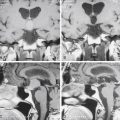
Table 54-7 also depicts preoperative radiographic criteria that have been frequently cited for improving outcome and limiting morbidity of ETV. Preoperative MRI optimally demonstrates all relevant anatomic features and should be obtained for all proposed ETV patients. Initially, confirmation of noncommunicating hydrocephalus of favorable cause should be established by the pattern of ventricular dilatation. Anatomic obstruction of CSF pathways between the aqueduct and the fourth ventricular outflow foramina may be visible on T2- or T1-weighted images. Additionally, T2-weighted images may reveal absence of the aqueductal CSF flow void frequently present in normal individuals. Extraventricular sites of obstruction, such as posterior fossa arachnoid scarring, may also cause noncommunicating hydrocephalus.124 In addition, ETV has been reported to successfully treat cases in which ventricular outlet obstruction is not apparent, such as idiopathic normal pressure hydrocephalus, as well as communicating hydrocephalus secondary to trauma, hypertensive intracranial hemorrhage, tuberculous meningitis, and subarachnoid hemorrhage.125–129 Given the significant risk of ETV failure in the face of prepontine cistern scarring,123 preoperative MRI with FIESTA sequences may prove useful in refining patient selection.
Once the patient’s suitability for the procedure has been established, the neurosurgeon must clarify the details of third ventricular anatomy that are likely to affect morbidity. First, the width of the third ventricle and diameter of the foramen of Monro must be sufficient to accommodate the endoscope of choice (see the later section on technique). Additionally, the thickness of the third ventricular floor and the anatomy of the proposed puncture site in relationship to vital structures, particularly the basilar artery and its branches, must be assessed. A downward-bulging third ventricular floor draped over the clivus has been cited as a prerequisite for this procedure in the past, but others have not found this to be necessary.97,103 Ultimately, the surgeon must be satisfied that there is no structural lesion (i.e., tumor or arteriovenous malformation) or anatomic variation that would render the procedure unduly difficult or hazardous. In cases of doubt, it is reasonable to visualize the floor of the third ventricle and abandon the procedure if the floor is unsuitable.
Technique
An ever-increasing variety of endoscopic equipment is available for neuroendoscopic procedures. For uncomplicated ETV, a 0- or 30-degree rigid scope is most commonly used. This offers superior optics and anatomic orientation. The Gaab endoscope (Johnson & Johnson, Randolph, MA), inserted through a 7-mm rigid cannula, provides the advantage of two working ports with a third for continuous irrigation. A 3.7-mm flexible steerable endoscope (Karl Storz, Tuttlingen, Germany) introduced through a No. 12 French peel-away sheath allows improved maneuverability within the ventricular system, at the expense of some image quality. Alternatively, this endoscope can be passed directly into the lateral ventricle without the use of a sheath in infants with a thin cortical mantle. In addition to performing the ETV, flexible scopes are useful for accessing more remote portions of the ventricular system (i.e., pineal recess or aqueduct), as well as for bilateral cauterization of the lateral ventricular choroid plexus. Several miniature fiberoptic endoscopes are also now available. These scopes can be inserted through a standard ventricular catheter; however, their inferior optics and lack of an irrigating or working channel limit their potential applications (i.e., ventricular catheter placement).
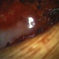
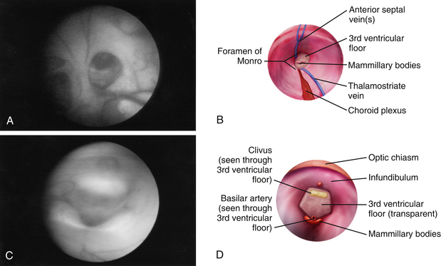
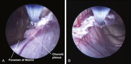
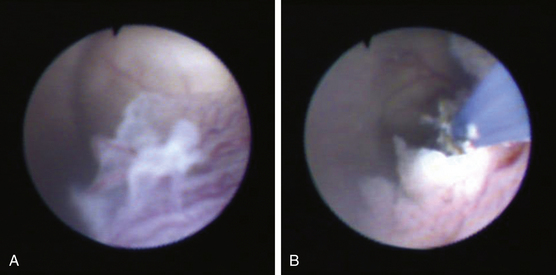
Once insertion of the endoscope into the lateral ventricle has been achieved, the foramen of Monro is located by identification of the choroid plexus and septal and thalamostriate veins (Figs. 54-6A and B and 54-7A). After passage of the endoscope through the foramen of Monro, the optic chiasm, infundibulum, mammillary bodies, massa intermedia, and aqueduct can all be observed along the floor of the third ventricle from anterior to posterior, depending on trajectory (Figs. 54-6C and D and Figs. 54-7B and G). A flexible scope is generally necessary to view the lamina terminalis, suprapineal recess, or third ventricular roof. In cases of obstructive hydrocephalus, a diamond-shaped transparent membrane is commonly seen between the mammillary bodies and the infundibulum. The dorsum sellae, clivus, and basilar artery are often visible through this membrane (Fig. 54-7B). This area of the third ventricular floor between the clivus and the basilar artery is the ideal site for ETV.
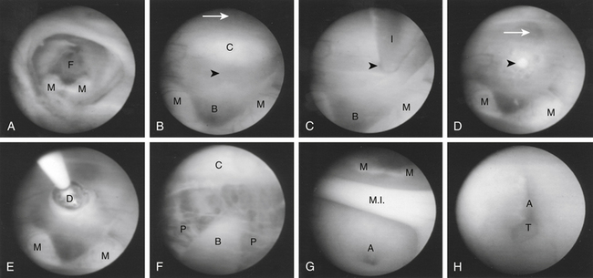
Numerous methods of perforating the third ventricular floor have been described that use the scope itself, a cautery unit, laser, or endoscopic instrument.96,99,103,130–132 We advise never penetrating the third ventricular floor with cautery or laser because of increased risk of damage to underlying structures, such as the basilar artery. A closed blunt biopsy forceps for initial fenestration can be used, followed by dilation of the stoma with a No. 4 French Fogarty balloon catheter (Fig. 54-7C through E). Care is taken to inflate the balloon with sterile irrigation fluid only under direct vision within the opening, because blindly withdrawing an inflated balloon from the basal cisterns carries a significant risk of injury to perforating vessels. Alternatively, if using a flexible endoscope, the floor can be penetrated with the tip of a Bugby wire, using no electrocautery, and the opening subsequently widened by gentle stretching at the margins of the developing stoma. This is easily accomplished by flexing the steerable tip of the endoscope. After adequate enlargement of the ventriculostomy, the scope can be advanced to inspect the prepontine and interpeduncular cisterns (Fig. 54-7F). The flexible endoscope also allows access to the lamina terminalis, which can be used as an alternative ETV site if technical or anatomic issues preclude use of the third ventricle floor.
In the past, postoperative CSF shunting was recommended to promote expansion of pericerebral CSF spaces and improve absorption.104,106,113 Compelling evidence suggests, however, that CSF flow through the ventriculostomy maintains its patency, and shunts can lead to closure of the opening.95,113 We do not recommend a coexisting CSF shunt and ETV.
Choroid Plexus Cauterization
Bilateral lateral ventricle CPC, when performed in combination with ETV, has been demonstrated to be significantly more successful than ETV alone in infants younger than 1 year.110–112 The combined procedure (ETV/CPC) can be performed with a flexible steerable ventriculoscope via a single approach through the right lateral corner of the anterior fontanel in the midpupillary line, as described earlier. After completing the ETV, attention is turned to the choroid plexus of the right lateral ventricle. Beginning at the right foramen of Monro, the plexus is cauterized with the tip of the Bugby wire (Fig. 54-8A). A monopolar current is used at its lowest effective setting. The tip of the wire is not buried in the substance of the plexus but rather is used to work along its surface, keeping the tip in view. It is imperative to avoid transgressing the ependyma or the choroidal fissure. The plexus is cauterized along its axis back to and including the glomus choroidea (Fig. 54-8B). The superior choroidal vein is typically in view, running along the surface of the plexus, and this is coagulated completely. Care must be taken to avoid injury to the thalamostriate and internal cerebral veins. Once at the atrium, the flexible scope is advanced slightly into the occipital horn posterior to the thalamus, where the tip is flexed and the scope slightly torqued to direct the procedure along the plexus within the temporal horn to its anterior extremity (Fig. 54-9A and B). Once all accessible plexus in the right lateral ventricle has been coagulated and shriveled, the left lateral ventricle is accessed. This requires a septostomy if the septum pellucidum is competent. The point for septostomy is chosen superior to the posterior margin of the foramen of Monro in an avascular region, avoiding the septal vein and its branches. A small circular area is cauterized and then penetrated with the Bugby wire. A cavum septum pellucidum requires deliberate fenestration of each distinct leaf. The scope is passed into the contralateral lateral ventricle, avoiding any contact with the underlying forniceal columns. The contralateral choroid plexus is then easily accessed and cauterized in the same fashion (Fig. 54-9B).
Outcome
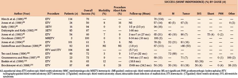
The goal of ETV and, to date, the best objectively quantifiable measure of a successful outcome is shunt independence. ETV has yielded a higher success rate with lower morbidity and mortality than earlier methods of third ventriculostomy. Mortality rates for open ventriculostomy procedures varied between 5% and 27%, with success rates of 37% to 75%.19,95,103,105,113,133 Percutaneous radiographic and later CT-guided techniques reduced this mortality rate to 2% to 7%, with a 44% to 75% rate of shunt independence.95,102,103,106,113,134 Studies using modern endoscopic techniques and equipment, with or without stereotactic CT or MRI guidance, have reported low morbidity (3% to 12%) and essentially no mortality, with success rates greater than 75% for carefully selected patient groups. Table 54-8 depicts the results of earlier ETV studies with success rates by cause where this information is available. The new success prediction scores cited previously have helped define appropriate indications and predict the likelihood of success in an individual patient. Objective measures for postoperative assessment of these patients need to be refined.
One of the most confusing aspects of outcome evaluation in ETV patients is the failure of the ventricles to return to normal size. Most studies report a gradual decrease in the ventricular size over months to years postoperatively, with resolution of periventricular edema and increased extracerebral spaces, coinciding with clinical improvement.95–98,113,135 One series of patients treated with either CSF shunts or ETV showed no difference in intellectual outcome despite enlarged ventricles in the ETV group.135 A more recent study of infants with myelomeningocele and hydrocephalus demonstrated no difference between patients treated by shunting or those treated by combined ETV/CPC in regard to early developmental outcomes.113 In that study, there was little difference among shunted patients, patients treated by ETV/CPC, and patients who required no hydrocephalus treatment in regard to ventricular size. Furthermore, no association was demonstrated between ventricle size and developmental outcome. Multiple authors have reported late failures, in which the ventriculostomy closes sometimes years postoperatively.97,109,136 However, late ETV failure appears to be rare. Importantly, in contrast to the ongoing lifetime risk of shunt failure, the majority of ETV failures have been shown to become apparent within 6 months of the procedure.112,115,135 Radiographic evaluation of suspected closure is confounded by the presence of persistently enlarged ventricles, and closure must often be suspected solely on the basis of clinical evidence.
Studies detailing the serial measurements of multiple radiographic indices of ventricular size postoperatively show that the third ventricular size responds more quickly (usually within 3 months) than the lateral ventricular size (2 years).135,137 Additionally, third ventricular size appears to correlate most closely with outcome in these patients.98,135,137 Several newer modalities appear promising as potential objective measures of ventriculostomy function. MRI detection of T2-weighted flow void around the ventriculostomy has been correlated with clinical outcome in ETV.138–140 This observation has proved most helpful in confirming ventriculostomy patency postoperatively, particularly in patients with persistent ventriculomegaly.139,140 Actual quantification of flow velocity through ventriculostomies has also been demonstrated by phase-contrast MRI and Doppler ultrasonography.141,142 Intraventricular pressure has been observed to return to normal over 3 months in a patient after third ventriculostomy who underwent concurrent implantation of a telemetric ICP monitor.143 For patients in whom an EVD is placed postoperatively, such as those undergoing ETV in the face of shunt failure, ICP may take several days to normalize, and serial lumbar puncture has been reported to facilitate this process.144 We hope that methods of quantifying ventriculostomy function will allow neurosurgeons to refine further the techniques necessary to improve outcome. Radiographic confirmation may also help define indications with more subjective outcomes, for example, the observation of less fulminant shunt malfunctions in patients after ventriculostomy.99
Complications
Several series of ETVs report no mortality and low morbidity (Table 54-8).95–101,109–112,116,139,145–147 The most common serious complications are related to structures in and around the floor of the third ventricle. In patients with aqueductal obstruction, the third ventricular floor is usually thinned out and transparent and the hypothalamic nuclei displaced laterally. When the floor is not thinned or the ventriculostomy is not performed at the preferred midline site, injury to the hypothalamus or bleeding can result. These complications have been attributed to direct pressure from the perforating instrument, elevated CSF temperature from cautery or the light source, or distention of the third ventricle from continuous irrigation without adequate drainage.98 Reported complications from injury to this area include the syndrome of inappropriate secretion of antidiuretic hormone, diabetes insipidus, loss of thirst, amenorrhea, and trancelike states.136,148 These complications are usually transient. Bradycardia is also observed occasionally, when perforating a thickened third ventricular floor, and a near-fatal cardiac arrest has been reported.149 Transient postoperative fevers, which frequently occur in these patients, are commonly attributed to irritation of the ependyma from blood or manipulation of the hypothalamus.131
Other structures at risk in this area include the third and sixth cranial nerves, fornix, and caudate. Injuries to all of these structures, usually transient or clinically silent, have been reported.136,148 The major life-threatening risk during the procedure is injury to the basilar artery and its branches. The basilar bifurcation is usually visible through the thinned third ventricular floor. Extreme caution should be taken to avoid injuring these vessels, particularly when preoperative imaging suggests a thickened ventricular floor or aberrant location (i.e., anterior to the mammillary bodies) of these vessels. We perform the initial fenestration with a blunt instrument rather than the cautery or laser to minimize the risk of arterial damage. Injury to these vessels can result in catastrophic hemorrhage, stroke, or pseudoaneurysm formation.150 Other routine complications, associated with most neurosurgical procedures, have also been observed. Superficial wound infections, meningitis and ventriculitis, subdural hematomas, and CSF leaks have all been described.98,136,148
Other Endoscopic Applications
Endoscopic techniques, with and without the addition of stereotactic assistance, are increasingly used for treating a variety of conditions and complications related to hydrocephalus. In stereotactic-guided techniques, the scope target can be selected and intervening structures (i.e., the foramen of Monro) can be chosen as part of the trajectory.95,151 CT- or MRI-based frame systems have commonly been supplanted by newer frameless stereotactic systems. These can be easily adapted for use with a rigid endoscope. These systems are particularly useful when planning the trajectory in patients with small ventricles, distorted anatomy as a result of prior shunting procedures or infection, or approaching intraventricular lesions. They are also helpful when operating in large ventricles where the light is diffused, in loculated ventricles where there is essentially no recognizable anatomy, and in CSF turbid from debris or blood when scope image quality is poor. Collapse of the ventricular system or cystic cavities can rapidly render the preoperative imaging data useless.
Intracranial cysts and loculated regions of the ventricular system have been successfully treated with these techniques.130,152,153 Endoscopic procedures for colloid cysts and suprasellar arachnoid cysts have been particularly successful.154–156 Several studies have examined the role of ventriculoscopic shunt catheter placement.157,158 However, a prospective, randomized study of the usefulness of this procedure failed to demonstrate any significant benefit in regard to shunt survival.159 Likewise, treatment of intraventricular tumors and their associated hydrocephalus with endoscopic techniques requires further study, particularly in midline posterior fossa tumors.98,160–164 Ventriculoscopic procedures for pineal, suprasellar, and tectal lesions have proved most useful to date.165–168 Further study and technical refinements will lead to many more potential uses for these procedures in the treatment of hydrocephalus and its associated causes. The challenge for neurosurgeons is to continue defining the indications and outcomes and refining the techniques for safely performing these useful procedures.
Drake J.M. Ventriculostomy for treatment of hydrocephalus. Neurosurg Clin N Am. 1993;4:657-666.
Drake J., Chumas P., Kestle J., et al. Late rapid deterioration after endoscopic third ventriculostomy: additional cases and review of the literature. J Neurosurg. 2006 Aug;105(2 suppl):118-126.
Greenfield J.P., Hoffman C., Kuo E., Christos P.J., Souweidane M.M. Intraoperative assessment of endoscopic third ventriculostomy success. JNS Peds. 2008;2:298-303.
Kulkarni A.V., Drake J.M., Mallucci C.L., et al. Canadian Pediatric Neurosurgery Study Group Endoscopic third ventriculostomy in the treatment of childhood hydrocephalus. J Pediatr. 2009;155:254-259.
Warf B.C. Comparison of endoscopic third ventriculostomy alone and combined with choroid plexus cauterization in infants younger than 1 year of age: a prospective study in 550 African children. J Neurosurg. 2005 Dec;103(6 suppl):475-481.
Warf B.C. Hydrocephalus in Uganda: the predominance of infectious origin and primary management with endoscopic third ventriculostomy. J Neurosurg. 2005 Jan;102(1 suppl):1-15.
Warf B.C., Campbell J.W. Combined endoscopic third ventriculostomy and choroid plexus cauterization as primary treatment of hydrocephalus for infants with myelomeningocele: long-term results of a prospective intent-to-treat study in 115 East African infants. J Neurosurg Pediatr. 2008 Nov;2(5):310-316.
Warf B.C., Kulkarni A. Endoscopic third ventriculostomy in the treatment of childhood hydrocephalus in Uganda: report of a scoring system that predicts success. J Neurosurg Pediatrics. 2010;5:143-148.
Warf B.C., Kulkarni A. Intraoperative assessment of cerebral aqueduct patency and cisternal scarring: impact on success of endoscopic third ventriculostomy in 403 African children. J Neurosurg Pediatrics. 2010;5:204-209.
1. Wiswell T.E., Tuttle D.J., Northam R.S., Simonds G.R. Major congenital neurologic malformations. A 17-year survey. Am J Dis child. 1990;144(1):61-67.
2. Chi J.H., Fullerton H.J., Gupta N. Time trends and demographics of deaths from congenital hydrocephalus in children in the United States: National Center for Health Statistics data, 1979 to 1998. Journal of Neurosurgery. 2005;103(2suppl):113-118.
3. Drake J.M., Kestle J.R., Milner R., et al. Randomized trial of cerebrospinal fluid shunt valve design in pediatric hydrocephalus. Neurosurgery. 1998;43:294-305.
4. Bondurant C.P., Jimenez D.F. Epidemiology of cerebrospinal fluid shunting. Pediatr Neurosurg. 1995;23:254-259.
5. Simon T.D., Riva-Cambrin J., Srivastava R., et al. Hydrocephalus Clinical Research Network. Hospital care for children with hydrocephalus in the United States: utilization, charges, comorbidities, and deaths. J Neurosurg Pediatr. 2008;1(2):131-137.
6. Nazir S., O’Brien M., Qureshi N.H., et al. Sensitivity of papilledema as a sign of shunt failure in children. Journal of AAPOS. 2009;13(1):63-66.
7. Yamada S., Miyazaki M., Kanazawa H., et al. Visualization of cerebrospinal fluid movement with spin labeling at MR imaging: preliminary results in normal and pathophysiologic conditions. Radiology. 2008;249(2):644-652.
8. Ashley W.W.Jr., McKinstry R.C., Leonard J.R., et al. Use of rapid-sequence magnetic resonance imaging for evaluation of hydrocephalus in children. Journal of Neurosurgery. 2005;103(2 suppl):124-130.
9. Greitz D. Cerebrospinal fluid circulation and associated intracranial dynamics. A radiologic investigation using MR imaging and radionuclide cisternography. Acta Radiol Suppl. 1993;386:1-23.
10. Johnston M., Zakharov A., Papaiconomou C., Salmasi G., Armstrong D. Evidence of connections between cerebrospinal fluid and nasal lymphatic vessels in humans, non-human primates and other mammalian species. Cerebrospinal Fluid Res. 2004;1:2.
11. Raimondi A.J. A unifying theory for the definition and classification of hydrocephalus. Childs Nerv Syst. 1994;10(1):2-12.
12. McCullough D.C. A history of the treatment of hydrocephalus. Concepts Neurosurg. 1990;3:1-10.
13. Fisher R.G. Surgery of the Congenital Anomalies. Baltimore: Williams & Wilkins; 1951.
14. Davidoff L.E. Treatment of hydrocephalus. Arch Surg. 1929;18:1737-1762.
15. Sharpe W. The operative treatment of hydrocephalus: a preliminary report of forty-one patients. Am J Med Sci. 1917;153:563-571.
16. Cushing H. The special field of neurological surgery. Cleveland Med J. 1905;4:1-25.
17. Ferguson A.H. Intraperitoneal diversion of the cerebrospinal fluid in cases of hydrocephalus. N Y Med. 1898;67:902.
18. Nicholl J.H. Case of hydrocephalus in which peritoneo-meningeal drainage has been carried out. Glasgow Med J. 1905;63:187-191.
19. Dandy W.E. Diagnosis and treatment of strictures of the aqueduct of Sylvius (causing hydrocephalus). Arch Surg. 1945;51:1-14.
20. Mixter W.J. Ventriculoscopy and puncture of the floor of the third ventricle. Boston Med Surg J. 1923;188:277-278.
21. Dandy W.E. Extirpation of the choroid plexus of the lateral ventricles in communicating hydrocephalus. Ann Surg. 1918;68:569-579.
22. Torkildsen A. A new palliative operation in cases of inoperable occlusion of the sylvian aqueduct. Acta Chir Scand. 1939;82:117-124.
23. Nulsen F.E., Spitz E.B. Treatment of hydrocephalus by direct shunt from ventricle to jugular vein. Surg Forum. 1952;2:399-403.
24. Wallman L.J. Shunting for hydrocephalus: an oral history. Neurosurgery. 1982;11:308-313.
25. Pudenz R.H. The surgical treatment of hydrocephalus—an historical review. Surg Neurol. 1981;15:15-26.
26. Fox J.L., McCullough D.C., Green R.C. Effect of cerebrospinal fluid shunts on intracranial pressure and on cerebrospinal fluid dynamics. 2: A new technique of pressure measurements: Results and concepts. 3: A concept of hydrocephalus. J Neurol Neurosurg Psychiatry. 1973;36:302-312.
27. Fox J.L., Portnoy H.D., Shulte R.R. Cerebrospinal fluid shunts: an experimental evaluation of flow rates and pressure values in the anti-siphon valve. Surg Neurol. 1973;1:299-302.
28. Chapman P.H., Cosman E.R., Arnold M.A. The relationship between ventricular fluid pressure and body position in normal subjects and subjects with shunts: a telemetric study. Neurosurgery. 1990;26:181-189.
29. Lind C.R., Correia J.A., Law A.J., Kejriwal R. A survey of surgical techniques for catheterising the cerebral lateral ventricles. J Clin Neurosci. 2008;15(8):886-890.
30. Clark S., Sangra M., Hayhurst C., et al. The use of noninvasive electromagnetic neuronavigation for slit ventricle syndrome and complex hydrocephalus in a pediatric population. Journal of Neurosurgery Pediatrics. 2008;2:430-434.
31. Whitehead W.E., Jea A., Vachhrajani S., Kulkarni A.V., Drake J.M. Accurate placement of cerebrospinal fluid shunt ventricular catheters with real-time ultrasound guidance in older children without patent fontanelles. J Neurosurg. 2007;107(5 suppl):406-410.
32. Jeelani N.U., Kulkarni A.V., Desilva P., Thompson D.N., Hayward R.D. Postoperative cerebrospinal fluid wound leakage as a predictor of shunt infection: a prospective analysis of 205 cases. J Neurosurg Pediatr. 2009;4(2):166-169.
33. Tuli S., O’Hayon B., Drake J., et al. Change in ventricular size and effect of ventricular catheter placement in pediatric patients with shunted hydrocephalus. Neurosurgery. 1999;45:1329-1333.
34. Sanders D.Y., Summers R., DeRouen L. Symptomatic pleural collection of cerebrospinal fluid caused by a ventriculopleural shunt. South Med J. 1997;90:345-346.
35. Beach C., Manthey D.E. Tension hydrothorax due to ventriculopleural shunting. J Emerg Med. 1998;16:33-36.
36. Decq P., Blanquet A., Yepes C. Percutaneous jugular placement of ventriculo-atrial shunts using a split sheath: Technical note. Acta Neurochir (Wien). 1995;136:92-94.
37. Aldana P.R., James H.E., Postlethwait R.A. Ventriculogallbladder shunts in pediatric patients. J Neurosurg Pediatr. 2008;1(4):284-287.
38. El Shafei I.L., El Shafei H.I. The retrograde ventriculo-sinus shunt (El Shafei RVS shunt). Rationale, evolution, surgical technique and long-term results. Pediatr Neurosurg. 2005 Nov-Dec;41(6):305-317.
39. Wu Y., Green N.L., Wrensch M.R., Zhao S., Gupta N. Ventriculoperitoneal shunt complications in California: 1990 to 2000. Neurosurgery. 2007;61:557-563.
40. Stein S.C., Guo W. Have we made progress in preventing shunt failure? A critical analysis. Journal of Neurosurgery Pediatrics. 2008;1:40-47.
41. Kestle J., Drake J., Milner R., et al. Long-term follow-up data from the Shunt Design Trial. Pediatr Neurosurg. 2000;33(5):230-236.
42. Drake J.M., Sainte-Rose C. The Shunt Book. New York: Blackwell Scientific; 1995.
43. Sainte-Rose C., Hooven M.D., Hirsch J.F. A new approach in the treatment of hydrocephalus. J Neurosurg. 1987;66:213-226.
44. Horton D., Pollay M. Fluid flow performance of a new siphon-control device for ventricular shunts. J Neurosurg. 1990;72:926-932.
45. Portnoy H.D., Schulte R.R., Fox J.L., et al. Anti-siphon and reversible occlusion valves for shunting in hydrocephalus and preventing post-shunt subdural hematomas. J Neurosurg. 1973;38:729-738.
46. Sotelo J., Izurieta M., Arriada N. Treatment of hydrocephalus in adults by placement of an open ventricular shunt. Journal of Neurosurgery. 2001;94:873-879.
47. Kan P., Walker M.L., Drake J.M., Kestle J.R.W. Predicting slitlike ventricles in children on the basis of baseline characteristics at the time of shunt insertion. J Neurosurg. 2007;106(5 suppl Pediatrics):347-349.
48. Secer H.I., Kural C., Kaplan M., et al. Comparison of the efficacies of antibiotic-impregnated ventricular catheters on the prevention of infections: an in vitro study. Pediatric neurosurgery. 2008;44(6):444-447.
49. Zabramski J.M., Whiting D., Darouiche R.O., et al. Efficacy of antimicrobial-impregnated external ventricular drain catheters: a prospective, randomized, controlled trial. J Neurosurg. 2003;98(4):725-730.
50. Govender S.T., Nathoo N., van Dellen J.R. Evaluation of an antibiotic-impregnated shunt system for the treatment of hydrocephalus. J Neurosurg. 2003;99(5):831-839.
51. Sciubba D.M., Stuart R.M., McGirt M.J., et al. Effect of antibiotic-impregnated shunt catheters in decreasing the incidence of shunt infection in the treatment of hydrocephalus. J Neurosurg. 2005;03(2 suppl):131-136.
52. Kan P., Kestle J. Lack of efficacy of antibiotic-impregnated shunt systems in preventing shunt infections in children. Childs Nerv Syst. 2007;23(7):773-777.
53. Ritz R., Roser F., Morgalla M., et al. Do antibiotic-impregnated shunts in hydrocephalus therapy reduce the risk of infection? An observational study in 258 patients. BMC Infect Dis. 2007;8(7):38.
54. Hayhurst C., Cooke R., Williams D., et al. The impact of antibiotic-impregnated catheters on shunt infection in children and neonates. Childs Nerv Syst. 2008;24(5):557-562.
55. Eymann R., Chehab S., Strowitzki M., Steudel W.I., Kiefer M. Clinical and economic consequences of antibiotic-impregnated cerebrospinal fluid shunt catheters. J Neurosurg Pediatr. 2008;1(6):444-450.
56. Richards H.K., Seeley H.M., Pickard J.D. Efficacy of antibiotic-impregnated shunt catheters in reducing shunt infection: data from the United Kingdom Shunt Registry. J Neurosurg Pediatr. 2009;4(4):389-393.
57. Parker S.L., Attenello F.J., Sciubba D.M., et al. Comparison of shunt infection incidence in high-risk subgroups receiving antibiotic-impregnated versus standard shunts. Childs Nerv Syst. 2009;25(1):77-83.
58. Tuli S., Drake J., Lawless J.L., Wigg M., Lamberti-Pasculli M. Risk factors for repeated shunt failures in pediatric patients with hydrocephalus. Journal of Neurosurgery. 2000;92:31-38.
59. Kestle J.R., Drake J.M., Cochrane D.D., et al. Lack of benefit of endoscopic ventriculoperitoneal shunt insertion: a multicenter randomized trial. J Neurosurg. 2003;98:284-290.
60. Smith E.R., Butler W.E., Barker F.G.2nd. In-hospital mortality rates after ventriculoperitoneal shunt procedures in the United States, 1998 to 2000: relation to hospital and surgeon volume of care. J Neurosurg. 2004;100(2 suppl Pediatrics):90-97.
61. Cochrane D.D., Kestle J. Ventricular shunting for hydrocephalus in children: patients, procedures, surgeons and institutions in English Canada, 1989-2001. Eur J Pediatr Surg. 2002;12(suppl 1):S6-S11.
62. Kestle J.R.W., Cochrane D.D. The influence of surgical operative experience on the duration of first ventriculoperitoneal shunt function and infection. Source: Pediatric Neurosurgery [1016-2291] Cochrane. 2003;38(6):295-301.
63. Kestle J.R.W., Cochrane D.D., Drake J.M. Shut insertion in the summer: is it safe? Journal of neurosurgery pediatrics. 2006;105(suppl 3):165-168.
64. Haines S.J., Walters B.C. Antibiotic prophylaxis for cerebrospinal fluid shunts: a metaanalysis. Neurosurgery. 1994;34:87-92.
65. Darouiche R.O., Wall M.J.Jr., Itani K.M., et al. Chlorhexidine–alcohol versus povidone–iodine for surgical-site antisepsis. N Engl J Med. 2010;362(1):18-26.
66. Horgan M.A., Piatt J.H. Shaving of the scalp may increase the rate of infection in CSF shunt surgery. Pediatr Neurosurg. 1997;26:180-184.
67. Kretschmer T., Braun V., Richter H- P. Neurosurgery without shaving: Indications and results. Br J Neurosurg. 2000;14:341-344.
68. Tanner J., Woodings D., Moncaster K.. Preoperative hair removal to reduce surgical site infection. Cochrane Database Syst Rev, 2006 Apr 19;2:CD004122
69. Tanner J., Parkinson H. Double gloving to reduce surgical cross-infection. Cochrane Database Syst Rev. 2006 Jul 19;3:CD003087.
70. Drake J.M., Kestle J.R., Tuli S. CSF shunts 50 years on—past, present and future. Childs Nerv Syst. 2000;16(10-11):800-804.
71. Dickerman R.D., McConathy W.J., Morgan J., et al. Failure rate of frontal versus parietal approaches for proximal catheter placement in ventriculoperitoneal shunts: revisited. Journal of clinical neuroscience. 2005;12(7):781-783.
72. Kim Y.B., Lee J.W., Lee K.S., Lee K.C. Image-guided placement of ventricular shunt catheter. J Clin Neurosci. 2006;13:50-54.
73. Borgbjerg B.M., Gjerris F., Albeck M.J., Hauerberg J., Børgesen S.V. A comparison between ventriculo-peritoneal and ventriculo-atrial cerebrospinal fluid shunts in relation to rate of revision and durability. Acta Neurochir (Wien). 1998;140(5):459-464. discussion 465
74. Lundar T., Langmoen I.A., Hovind K.H. Fatal cardiopulmonary complications in children treated with ventriculoatrial shunts. Childs Nerv Syst. 1991;7:215-217.
75. Piatt J.H., Homann H.J. Cor pulmonale: a lethal complication of ventriculoatrial CSF diversion. Childs Nerv Syst. 1989;5:29-31.
76. Lam H.P., Heilman C.B. Ventricular access device versus ventriculosubgaleal shunt in post hemorrhagic hydrocephalus associated with prematurity. J Matern Fetal Neonatal Med. 2009;22(11):1097-1101.
77. Iskandar B.J., Tubbs S., Mapstone T.B., et al. Death in shunted hydrocephalic children in the 1990s. Pediatr Neurosurg. 1998;28(4):173-176.
78. Acakpo-Satchivi L., Shannon C.N., Tubbs R.S., et al. Death in shunted hydrocephalic children: a follow-up study. Childs Nerv Syst. 2008;24(2):197-201.
79. Piatt J.H.Jr. Pumping the shunt revisited: a longitudinal study. Pediatr Neurosurg. 1996;25:73-76.
80. Bayston R., Hart C.A., Barnicoat M. Intraventricular vancomycin in the treatment of ventriculitis associated with cerebrospinal fluid shunting and drainage. J Neurol Neurosurg Psychiatry. 1987;50:1419-1423.
81. Mortellaro V.E., Chen M.K., Pincus D., et al. Infectious risk to ventriculo-peritoneal shunts from gastrointestinal surgery in the pediatric population. J Pediatr Surg. 2009 Jun;44(6):1201-1204. discussion 1204–1205
82. Drake J.M., Kulkarni A.V. Cerebrospinal fluid shunt infections. Neurosurg Q. 1993;3:283-294.
83. Langley J.M. Design for a study of the risk factors for cerebrospinal fluid shunt infection. Master’s thesis, McMaster University, Hamilton, Ontario, 1989. J Neurosurg Pediatr. 2008 May;1(5):366-372.
84. Arnell K., Cesarini K., Lagerqvist-Widh A., Wester T., Sjölin J. Cerebrospinal fluid shunt infections in children over a 13-year period: anaerobic cultures and comparison of clinical signs of infection with Propionibacterium acnes and with other bacteria. J Neurosurg Pediatr. 2008;1(5):366-372.
85. Meirovitch J., Kitai-Cohen Y., Keren G., et al. Cerebrospinal fluid shunt infections in children. Pediatr Infect Dis J. 1987;6:921-924.
86. Brydon H.L., Bayston R., Hayward R., Harkness W. Reduced bacterial adhesion to hydrocephalus shunt catheters mediated by cerebrospinal fluid proteins. J Neurol Neurosurg Psychiatry. 1996;60:671-675.
87. Brown E.M., Edwards R.J., Pople I.K. Conservative management of patients with cerebrospinal fluid shunt infections. Neurosurgery. 2008;2(62 suppl):661-669.
88. James H.E., Walsh J.W., Wilson H.D., et al. Prospective randomized study of therapy in cerebrospinal fluid shunt infection. Neurosurgery. 1980;7:459-463.
89. Olson S. The problematic slit ventricle syndrome. A review of the literature and proposed algorithm for treatment. Pediatr Neurosurg. 2004;40(6):264-269.
90. Britz G.W., Avellino A.M., Schaller R., Loeser J.D. Percutaneous placement of ventriculoatrial shunts in the pediatric population. Pediatr Neurosurg. 1998 Sep;29(3):161-163.
91. Grant J.A. Victor Darwin Lespinasse: a biographical sketch. Neurosurgery. 1996;39:1232-1237.
92. Dandy W.E. An operative procedure for hydrocephalus. Bull Johns Hopkins Hosp. 1922;33:189-190.
93. Fay T., Grant F.C. Ventriculoscopy and intraventricular photography in internal hydrocephalus. JAMA. 1966;80:461-463.
94. Griffith H.B. Technique of fontanel and persutural ventriculoscopy in infants. Childs Brain. 1975;1:359-363.
95. Kelly P.J. Stereotactic third ventriculostomy in patients with nontumoral adolescent/adult onset aqueductal stenosis and symptomatic hydrocephalus [see Comment in J Neurosurg 76:890-891, 1992]. J Neurosurg. 1991;75:865-873.
96. Jones R.F., Teo C., Stening W.A., Kwok C.T. Neuroendoscopic third ventriculostomy. In: Manwaring K.H., Crone K.R. Neuroendoscopy. New York: Mary Ann Liebert; 1992:63-77.
97. Jones R.F., Kwok B.C., Stening W.A., Vonau M. The current status of endoscopic third ventriculostomy in the management of noncommunicating hydrocephalus. Minim Invasive Neurosurg. 1994;37:28-36.
98. Sainte-Rose C., Chumas P. Endoscopic third ventriculostomy. Tech Neurosurg. 1996;1:176-184.
99. Jones R.F., Stening W.A., Brydon M. Endoscopic third ventriculostomy. Neurosurgery. 1990;26:86-91.
100. Teo C., Jones R. Management of hydrocephalus by endoscopic third ventriculostomy in patients with myelomeningocele. Pediatr Neurosurg. 1996;25:57-63.
101. Brockmeyer D., Abtin K., Carey L., Walker M.L. Endoscopic third ventriculostomy: an outcome analysis. Pediatr Neurosurg. 1998;28:236-240.
102. Jaksche H., Loew F. Burr hole third ventriculo-cisternostomy: An unpopular but effective procedure for treatment of certain forms of occlusive hydrocephalus. Acta Neurochir (Wien). 1986;79:48-51.
103. Drake J.M. Ventriculostomy for treatment of hydrocephalus. Neurosurg Clin N Am. 1993;4:657-666.
104. Natelson S.E. Early third ventriculostomy in meningomyelocele infants—shunt independence? Childs Brain. 1981;8:321-325.
105. Patterson R.H.Jr., Bergland R.M. The selection of patients for third ventriculostomy based on experience with 33 operations. J Neurosurg. 1968;29:252-254.
106. Sayers M.P., Kosnik E.J. Percutaneous third ventriculostomy: Experience and technique. Childs Brain. 1976;2:24-30.
107. Vries J.K., Friedman W.A. Postoperative evaluation of third ventriculostomy patients using 111In-DTPA. Childs Brain. 1980;6:200-205.
108. Jones R.F., Kwok B.C., Stening W.A., Vonau M. Neuroendoscopic third ventriculostomy: a practical alternative to extracranial shunts in noncommunicating hydrocephalus. Acta Neurochir Suppl. 1994;61:79-83.
109. Warf B.C. Hydrocephalus in Uganda: the predominance of infectious origin and primary management with endoscopic third ventriculostomy. J Neurosurg. 2005 Jan;102(1 suppl):1-15.
110. Warf B.C. Comparison of endoscopic third ventriculostomy alone and combined with choroid plexus cauterization in infants younger than 1 year of age: a prospective study in 550 African children. J Neurosurg. 2005 Dec;103(6 suppl):475-481.
111. Warf B.C. Endoscopic third ventriculostomy and choroid plexus cauterization for pediatric hydrocephalus. Clin Neurosurg. 2007;54:78-82.
112. Warf B.C., Campbell J.W. Combined endoscopic third ventriculostomy and choroid plexus cauterization as primary treatment of hydrocephalus for infants with myelomeningocele: long-term results of a prospective intent-to-treat study in 115 East African infants. J Neurosurg Pediatr. 2008 Nov;2(5):310-316.
113. Warf B., Ondoma S., Kulkarni A., et al. Neurocognitive outcome and ventricular volume in children with myelomeningocele treated for hydrocephalus in Uganda. J Neurosurg Pediatr. 2009 Dec;4(6):564-570.
114. Kulkarni A.V., Drake J.M., Mallucci C.L., et al. Canadian Pediatric Neurosurgery Study Group Endoscopic third ventriculostomy in the treatment of childhood hydrocephalus. J Pediatr. 2009;155:254-259.
115. Warf B.C., Kulkarni A. Endoscopic third ventriculostomy in the treatment of childhood hydrocephalus in Uganda: report of a scoring system that predicts success. J Neurosurg Pediatrics. 2010;5:143-148.
116. Baskin J.J., Manwaring K.H., Rekate H.L. Ventricular shunt removal: the ultimate treatment of the slit ventricle syndrome. J Neurosurg. 1998;88:478-484.
117. Jones R.F., Stening W.A., Kwok B.C., Sands T.M. Third ventriculostomy for shunt infections in children. Neurosurgery. 1993;32:855-859.
118. Yamamoto M., Oka K., Ikeda K., Tomonaga M. Percutaneous flexible neuroendoscopic ventriculostomy in patients with shunt malfunction as an alternative procedure to shunt revision. Surg Neurol. 1994;42:218-223.
119. Perlman B.B. Percutaneous third ventriculostomy in the treatment of a hydrocephalic infant with aqueduct stenosis. Int Surg. 1968;49:443-448.
120. Reddy K., Fewer H.D., West M., Hill N.C. Slit ventricle syndrome with aqueduct stenosis: third ventriculostomy as definitive treatment [see Comment in Neurosurgery 25:317-318, 1989]. Neurosurgery. 1988;23:756-759.
121. Hoffman H.J., Harwood-Nash D., Gilday D.L. Percutaneous third ventriculostomy in the management of noncommunicating hydrocephalus. Neurosurgery. 1980;7:313-321.
122. Greenfield J.P., Hoffman C., Kuo E., Christos P.J., Souweidane M.M. Intraoperative assessment of endoscopic third ventriculostomy success. JNS Peds. 2008;2:298-303.
123. Warf B.C., Kulkarni A. Intraoperative assessment of cerebral aqueduct patency and cisternal scarring: impact on success of endoscopic third ventriculostomy in 403 African children. J Neurosurg Pediatrics. 2010;5:204-209.
124. Kehler U., Gliemroth J. Extraventricular intracisternal obstructive hydrocephalus—a hypothesis to explain successful 3rd ventriculostomy in communicating hydrocephalus. Pediatr Neurosurg. 2003;28:98-101.
125. Gangemi M., Buonamassa S., Colella G., de Divitiis E. Endoscopic third ventriculostomy in idiopathic normal pressure hydrocephalus. Neurosurgery. 2004;55:129-134.
126. Hailong F., Guangfu H., Haibin T., et al. Endoscopic third ventriculostomy in the management of communicating hydrocephalus: a preliminary study. J Neurosurg. 109, 2008. 923–230
127. Jonathan A., Rajshkahar V. Endoscopic third ventriculostomy for chronic hydrocephalus after tuberculous meningitis. Surg Neurol. 2005;63:32-35.
128. Meier U., Zeilinger F.S., Schonher B. Endoscopic ventriculostomy versus shunt operation in normal pressure hydrocephalus: diagnosis and indication. Acta Neurochir Suppl. 2000;76:563-566.
129. Mitchell P., Mathew B. Third ventriculostomy in normal pressure hydrocephalus. Br J Neurosurg. 1999;13:382-385.
130. Heilman C.B., Cohen A.R. Endoscopic ventricular fenestration using a “saline torch.”. J Neurosurg. 1991;74:224-229.
131. Sainte-Rose C. Third ventriculostomy. In: Manwaring K.H., Crone K.R. Neuroendoscopy. New York: Mary Ann Liebert; 1992:47-62.
132. Crone K.R. Endoscopic technique for removal of adherent ventricular catheters. In: Manwaring K.H., Crone K.R. Neuroendoscopy. New York: Mary Ann Liebert; 1992:41-46.
133. Scarff J.E. Evaluation of treatment of hydrocephalus: results of third ventriculostomy and endoscopic cauterization of choroid plexuses compared with mechanical shunts. Arch Neurol. 1966;14:382-391.
134. Forjaz S., Martelli N., Latuf N. Hypothalamic ventriculostomy with catheter: technical note. J Neurosurg. 1968;29:655-659.
135. Oka K., Go Y., Kin Y., et al. The radiographic restoration of the ventricular system after third ventriculostomy. Minim Invasive Neurosurg. 1995;38:158-162.
136. Drake J., Chumas P., Kestle J., et al. Late rapid deterioration after endoscopic third ventriculostomy: additional cases and review of the literature. J Neurosurg. 2006 Aug;105(2 suppl):118-126.
137. Schwartz T.H., Yoon S.S., Cutruzzola F.W., Goodman R.R. Third ventriculostomy: post-operative ventricular size and outcome. Minim Invasive Neurosurg. 1996;39:122-129.
138. Jack C.R.Jr., Kelly P.J. Stereotactic third ventriculostomy: Assessment of patency with MR imaging. AJNR Am J Neuroradiol. 1989;10:515-522.
139. Goumnerova L.C., Frim D.M. Treatment of hydrocephalus with third ventriculocisternostomy: outcome and CSF flow patterns. Pediatr Neurosurg. 1997;27:149-152.
140. Wilcock D.J., Jaspan T., Worthington B.S., Punt J. Neuro-endoscopic third ventriculostomy: evaluation with magnetic resonance imaging. Clin Radiol. 1997;52:50-54.
141. Lev S., Bhadelia R.A., Estin D., et al. Functional analysis of third ventriculostomy patency with phase-contrast MRI velocity measurements. Neuroradiology. 1997;39:175-179.
142. Wilcock D.J., Jaspan T., Punt J. CSF flow through third ventriculostomy demonstrated with colour Doppler ultrasonography. Clin Radiol. 1996;51:127-129.
143. Frim D.M., Goumnerova L.C. Telemetric intraventricular pressure measurements after third ventriculocisternostomy in a patient with noncommunicating hydrocephalus. Neurosurgery. 1997;41:1425-1428.
144. Cinalli G., Spennato P., Ruggiero C., et al. Intracranial pressure monitoring and lumbar puncture after endoscopic third ventriculostomy in children. Neurosurgery. 2006 Jan;58(1):126-136.
145. Hirsch J.F., Hirsch E., Sainte-Rose C., et al. Stenosis of the aqueduct of Sylvius: etiology and treatment. J Neurosurg Sci. 1986;30:29-39.
146. Dalrymple S.J., Kelly P.J. Computer-assisted stereotactic third ventriculostomy in the management of noncommunicating hydrocephalus. Stereotact Funct Neurosurg. 1992;59:105-110.
147. Goodman R.R. Magnetic resonance imaging-directed stereotactic endoscopic third ventriculostomy. Neurosurgery. 1993;32:1043-1047.
148. Teo C., Rahman S., Boop F.A., Cherny B. Complications of endoscopic neurosurgery. Childs Nerv Syst. 1996;12:248-253.
149. Handler M.H., Abbott R., Lee M. A near-fatal complication of endoscopic third ventriculostomy: case report. Neurosurgery. 1994;35:525-527.
150. McLaughlin M.R., Wahlig J.B., Kaufmann A.M., Albright A.L. Traumatic basilar aneurysm after endoscopic third ventriculostomy: case report. Neurosurgery. 1997;41:1400-1403.
151. Zamorano L., Chavantes C., Moure F. Endoscopic stereotactic interventions in the treatment of brain lesions. Acta Neurochir Suppl. 1994;61:92-97.
152. Lewis A.I., Keiper G.L.Jr., Crone K.R. Endoscopic treatment of loculated hydrocephalus. J Neurosurg. 1995;82:780-785.
153. Cohen A.R. Endoscopic ventricular surgery. Pediatr Neurosurg. 1993;19:127-134.
154. Rappaport Z.H. Suprasellar arachnoid cysts: options in operative management. Acta Neurochir (Wien). 1993;122:71-75.
155. Decq P., Brugieres P., Le Guerinel C., et al. Percutaneous endoscopic treatment of suprasellar arachnoid cysts: ventriculocystostomy or ventriculocystocisternostomy? Technical note. J Neurosurg. 1996;84:696-701.
156. Lewis A.I., Crone K.R., Taha J., et al. Surgical resection of third ventricle colloid cysts. Preliminary results comparing transcallosal microsurgery with endoscopy [see Comment in J Neurosurg 81:174-178, 1994]. J Neurosurg. 1994;81:174-178.
157. Ure B.M., Holschneider A.M. Ventriculoscopic implantation of ventricular shunts in children with hydrocephalus. Eur J Pediatr Surg. 1997;7:299-300.
158. Kellnar S., Boehm R., Ring E. Ventriculoscopy-aided implantation of ventricular shunts in patients with hydrocephalus. J Pediatr Surg. 1995;30:1450-1451.
159. Kestle J.R., Drake J.M., Cochrane D.D., et al. Endoscopic Shunt Insertion Trial participants. Lack of benefit of endoscopic ventriculoperitoneal shunt insertion: a multicenter randomized trial. J Neurosurg. 2003 Feb;98(2):284-290.
160. Bhatia R., Tahir M., Chandler C.L. The management of hydrocephalus in children with posterior fossa tumours: the role of pre-resectional endoscopic third ventriculostomy. Pediatr Neurosurg. 2009;45(3):186-191.
161. Tamburrini G., Pettorini B.L., Massimi L., Caldarelli M., Di Rocco C. Endoscopic third ventriculostomy: the best option in the treatment of persistent hydrocephalus after posterior cranial fossa tumour removal? Childs Nerv Syst. 2008 Dec;24(12):1405-1412.
162. Morelli D., Pirotte B., Lubansu A., et al. Persistent hydrocephalus after early surgical management of posterior fossa tumors in children: is routine preoperative endoscopic third ventriculostomy justified? J Neurosurg. 2005 Sep;103(3 suppl):247-252.
163. Fritsch M.J., Doerner L., Kienke S., Mehdorn H.M. Hydrocephalus in children with posterior fossa tumors: role of endoscopic third ventriculostomy. J Neurosurg. 2005 Jul;103(1 suppl):40-42.
164. Ruggiero C., Cinalli G., Spennato P., et al. Endoscopic third ventriculostomy in the treatment of hydrocephalus in posterior fossa tumors in children. Childs Nerv Syst. 2004 Nov;20(11-12):828-833. Epub 2004 Jun 25
165. Ellenbogen R.G., Moores L.E. Endoscopic management of a pineal and suprasellar germinoma with associated hydrocephalus: technical case report. Minim Invasive Neurosurg. 1997;40:13-15.
166. Drake J. Neuroendoscopy Tumour Biopsy. New York: Mary Ann Leibert; 1992.
167. Ferrer E., Santamarta D., Garcia-Fructuoso G., et al. Neuroendoscopic management of pineal region tumours. Acta Neurochir (Wien). 1997;139:12-20.
168. Oka K., Yamamoto M., Nagasaka S., Tomonaga M. Endoneurosurgical treatment for hydrocephalus caused by intraventricular tumors. Childs Nerv Syst. 1994;10:162-166.