Mechanics of Ventilation
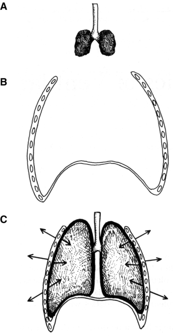
A As described in Chapter 4, the lung and the thorax are lined by thin connective tissues sheets: the parietal pleura on the inside of the thoracic cage and the visceral pleura on the outside of the lung and mediastinum.
B These two pleurae are in contact with each other, separated by only a thin film of fluid.
C Because the lungs have a tendency to contract inward and the thorax expands outward during normal breathing, a negative (subatmospheric) pressure is maintained between the pleurae (Figure 5-1).
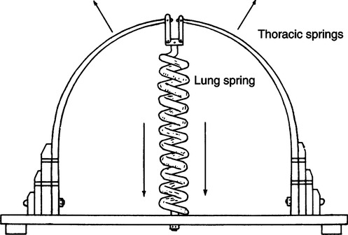
D A convenient way of viewing the lung-thorax system is to consider it a two-spring system held together by the pleura (Figure 5-2). The thorax can be conceptualized as a band spring tending to expand outward, and the lung can be described as a coil spring tending to contract inward.
E If the sternum is split and the pleura separated but not opened, the lung and thorax move to their independent resting positions (see Figure 5-1).
F If air is allowed to enter the potential pleural space, a pneumothorax develops.
G Any interference with the integrity of the pleura can interfere with ventilation.
II Pulmonary Pressures and Gradients
A Six pressures are frequently referred to when discussing ventilation:
1. Mouth pressure (Pao): The pressure at the entry of the respiratory system, synonymous with end-expiratory pressure or airway opening pressure.
2. Alveolar pressure (Palv): The pressure within the alveoli; also referred to as intrapulmonary pressure. It is equal to mouth pressure, when all gas flow stops, is equilibrated, and the glottis is open.
3. Pleural pressure (Ppl): The pressure within the potential pleural space; also referred to as intrathoracic pressure.
4. Esophageal pressure (Pes): Pressure measured within the esophagus. When the pressure is properly determined, changes in esophageal pressure reflect changes in pleural pressure.
5. Body surface pressure (Pbs): Equal to atmospheric pressure (PATM).
6. Abdominal pressure (Pab): Pressure measured in the abdominal cavity.
B When the mechanics of breathing are discussed, four pressure gradients are commonly defined (Figure 5-3):
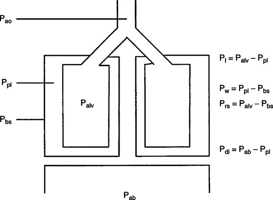
1. Transpulmonary pressure (Pl): The pressure difference across the lung (alveolar-pleural pressure, Pl = Palv − Ppl).
a. During resting spontaneous breathing maximally equals approximately 3 to 4 cm H2O.
b. During forced spontaneous breathing maximally may exceed 25 cm H2O.
c. During assisted ventilation may be from 1 to approximately 20 cm H2O dependent on patient effort.
d. During controlled ventilation the value is approximately 5 cm H2O under normal circumstances because alveolar and pleural pressures increase equal levels as inspiration continues.
e. The stiffer the lung, the greater the differences between alveolar and pleural pressures during spontaneous, assisted, and controlled ventilation.
f. The stiffer the chest, the smaller the differences between alveolar and pleural pressure during spontaneous, assisted, and controlled ventilation.
2. Transthoracic pressure (PW): The pressure difference across the thorax (pleural-body surface pressure, Pw = Ppl − Pbs).
a. During spontaneous, assisted, and controlled breathing the transthoracic pressure is larger than the transpulmonary pressure by approximately 3 to 5 cm H2O, depending on the stiffness of the lung and thorax and airway resistance.
b. The stiffer the lung and thorax or the greater the airway resistance, the greater the transthoracic pressure.
3. Transrespiratory pressure (Prs): The pressure difference across the lung-thorax system; also referred to as the transairway pressure (alveolar-body surface pressure, Prs = Palv − Pbs).
a. During spontaneous, assisted, and controlled breathing the transrespiratory pressure is essentially equal to the change in alveolar pressure and tends to track transpulmonary pressures.
b. Transrespiratory pressure is most affected by changes in the chest wall (including abdominal pressure). The stiffer the chest wall the greater the transrespiratory pressure.
4. Transdiaphragmatic pressure (Pdi): The pressure difference across the diaphragm (abdominal-pleural pressure, Pdi = Pab − Ppl).
a. During spontaneous breathing the transdiaphragmatic pressure is always greater than the transpulmonary pressure by a few cm H2O. This is true because as the pleural pressure decreases, the abdominal pressure increases.
b. During assisted ventilation the transdiaphragmatic pressure is initially slightly greater than the transpulmonary pressure, but as positive pressure is delivered pleural and abdominal pressures increase to bring transdiaphragmatic pressure close to zero.
c. During controlled ventilation the transdiaphragmatic pressure changes little from zero because the diaphragm does not actively contract and pleural and abdominal pressures increase, thus there is little change in transdiaphragmatic pressure.
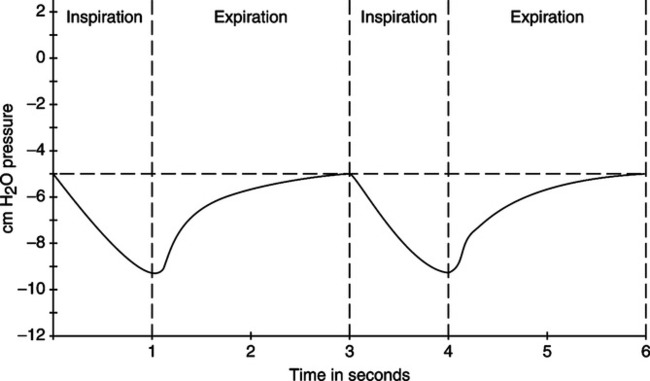
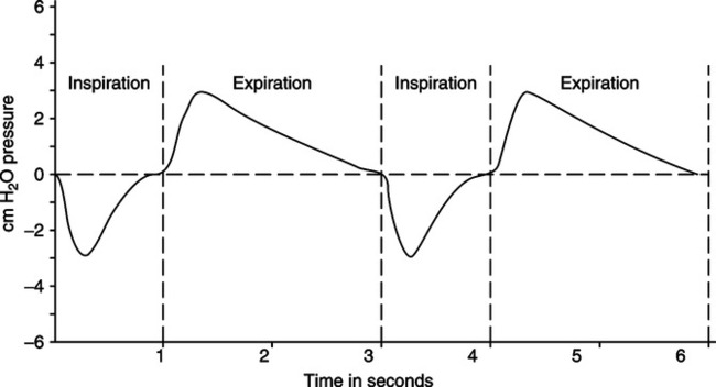
A Figures 5-4 and 5-5 depict the intrapleural (intrathoracic) and intrapulmonary pressure curves during normal resting ventilation.
B At functional residual capacity (FRC) level or resting exhalation, the intrapleural pressure is approximately −5 cm H2O, whereas the intrapulmonary pressure is zero (atmospheric; Figure 5-6).
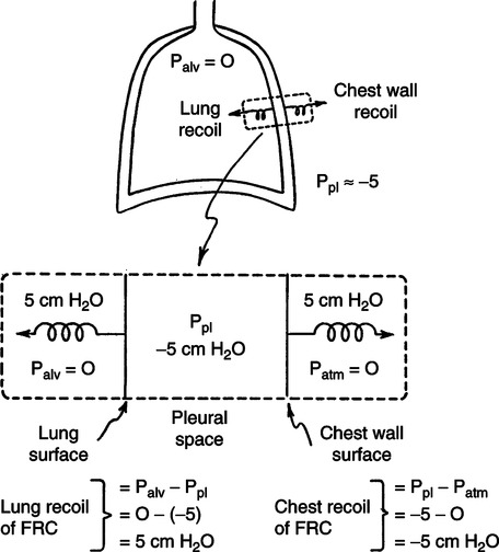
1. The transpulmonary pressure at FRC is thus equal to 5 cm H2O.
2. The transpulmonary pressure is also referred to as the alveolar distending pressure.
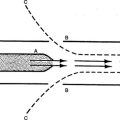
C Because the lung is a valveless pump, when gas flow stops and the glottis is open, intrapulmonary and atmospheric pressures are equal (i.e., the transrespiratory pressure gradient is zero).
1. A negative transrespiratory pressure causes gas to enter the lung.
2. A positive transrespiratory pressure causes gas to exit the lung.
D Pressure gradients causing inspiration are established by contraction of the diaphragm, intercostals, and scalene muscles.
E With inspiratory muscle contraction, the thoracic cavity expands, causing the intrapleural pressure to become more negative (approximately −9 cm H2O).
F This pressure decrease increases the volume of the lung. Because of the relationship of the two pleura, the lungs must expand as the thorax expands.
G The expansion of the lung decreases the intrapulmonary pressure to approximately −3 cm H2O.
H The decreased intrapulmonary pressure establishes a pressure gradient with atmosphere, causing gas to enter the lung.
I Once the intrapulmonary pressure is returned to normal by gas entering the lung, inspiration stops.
J Boyle’s law explains all of the pressure-volume changes described in breathing.
A Exhalation is normally a passive process. The lung-thorax system is returned to its resting state as a result of the elastic recoil of the lung.
B Relaxation of the muscles of inspiration allows the intrapleural pressure to return to baseline (−5 cm H2O); as a result, the intrapulmonary pressure increases to approximately +3 cm H2O.
C Because the transrespiratory pressure is positive, gas leaves the lung.
D Lung volume returns to the FRC level, and the transrespiratory pressure returns to zero.
A Ventilation is opposed by three major factors:
B Elastic resistance is a result of distortion of pulmonary elastic tissue. Elastic resistance is established based on:
C Nonelastic resistance is primarily the resistance to gas flow. It is equivalent to the frictional resistance of solids moving across each other. Overall nonelastic resistance is the combined effect of:
D Inertia is the tendency of a body in motion to stay in motion and a body at rest to stay at rest.
A Surface tension is the force occurring at the interface between a liquid and another liquid or a gas that tends to cause the liquid to occupy the smallest volume possible (see Chapter 2).
B Surface tension causes alveoli to decrease in size and would cause collapse were it not for the presence of a pulmonary surfactant secreted by type II alveolar cells.
C The volume of surfactant produced by the respiratory tract is relatively constant. As a result, the effect the surfactant exerts is indirectly related to the surface area it covers.
D At FRC there is a large amount of surfactant applied per unit area. This causes a significant reduction in pressure as a result of surface tension, with the following results:
1. Prevention of alveolar collapse on exhalation (preventing alveoli from reaching their critical volume).
2. Reduction in pressure needed to overcome surface tension as inspiration begins.
E At maximum inspiration, a small volume of surfactant is applied per unit area. Thus, the pressure as a result of surface tension tending to collapse the alveoli is great. This pressure assists in normal passive exhalation.
F Pressures as a result of surface tension:
G As a result the pressure-volume relationship of the lung is different during inspiration and expiration; a hysteresis exists (Figure 5-7). Greater volume is maintained in the lung for a given pressure during exhalation than during inspiration.
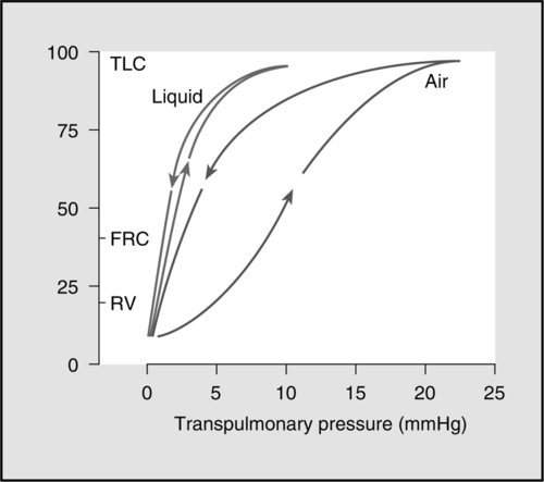
H If the lung is filled with saline instead of air, much less pressure is needed to expand it with saline because the effect of surface tension is eliminated and the hysteresis disappears (see Figure 5-7).
I The effect of surface tension cannot be evaluated directly. Changes in surface tension cause a change in compliance or elastance of the lung.
J An increase in surface tension increases elastic resistance to ventilation and is reflected in a decrease in compliance, causing an increase in the work of breathing.
A Compliance is the ease of distention of the lung-thorax system and is inversely related to elastance (see Chapter 2).
B Compliance is normally a static measurement so as to eliminate the effects of nonelastic resistance.
C Compliance is determined by comparing the change in volume in a system with the pressure necessary to maintain the volume change:
< ?xml:namespace prefix = "mml" />
 (1)
(1)D In the respiratory system, there are basically three types of compliance (Figure 5-8):
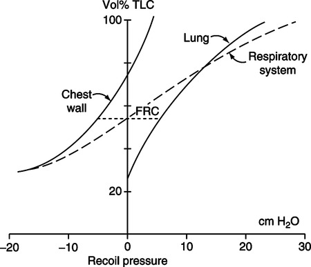
E In the lung-thorax system, the tendency of the lung is to collapse to its resting position, and the tendency of the thorax is to expand to its resting position.
F The FRC is that volume maintained in the lung at the resting expiratory position as a result of the equal and opposing effects of pulmonary (lung) and thoracic (chest wall) compliance.
G Total compliance of the lung-thorax system is a result of the interaction of pulmonary and thoracic compliance (see Figure 5-8).
H Compliance is linear only at relatively normal tidal volumes. As the lung volume exceeds or falls below tidal levels, compliance decreases. Thus, the total compliance curve is significantly distorted as lung volume approaches residual volume (RV) or total lung capacity (TLC; see Figure 5-8).
1. As lung volume approaches TLC, the tendency of the lung to collapse far outweighs the tendency of the thorax to expand. Specifically, the thorax reaches its resting position at 70% of TLC. Beyond this level the thorax tends to collapse. Because the lung has been distorted significantly beyond its resting position, continued pulmonary expansion requires greater force. At TLC an individual cannot exert sufficient force to continue lung expansion.
2. As the lung volume approaches RV, the tendency of the thorax to expand far outweighs the tendency of the lung to collapse. This occurs because the lung is now near its resting point, whereas the thorax is significantly distorted from its resting point. At RV, the tendency of the thorax to expand is so great that the individual cannot voluntarily exhale a larger volume.
I Total respiratory system compliance (Ctotal) is determined by dividing the tidal volume (VT) by the static pressure necessary to maintain the VT in the lung. Pressure should be measured at the patient’s mouth. In the average young adult, total respiratory system compliance measured in the normal VT range is typically equal to 0.08 to 0.1 L/cm H2O, or 80 to 100 ml/cm H2O.
J Pulmonary compliance (Cpul) is determined by dividing the VT by the static pressure necessary to maintain the VT in the lung. The pressure measured should reflect changes in intrapleural pressures. Pressure recorded at the level of the midesophagus accurately reflects pleural pressure changes. In the average young adult, pulmonary compliance (Cpul) is typically equal to 0.16 to 0.2 L/cm H2O, or 160 to 200 ml/cm H2O.
K Thoracic compliance (Cth) is a calculated value based on the following equation:
 (2)
(2)L Changes in total respiratory system compliance (Ctotal) reflect total elastic resistance to ventilation.
1. Total compliance reflects surface tension and tissue elastance.
2. A decrease in total compliance results in a decrease in FRC.
3. An increase in total compliance results in an increase in FRC.
4. Alterations in pulmonary or thoracic compliance result in an alteration of total compliance.
M With an increase in total respiratory system compliance, there is a corresponding decrease in elastance. This tends to make inspiration easier but also makes expiratory more difficult. In this situation a slow, deep ventilatory pattern minimizes the work of breathing.
N With a decrease in total respiratory system compliance, there is a corresponding increase in elastance. This tends to make inspiration more difficult but makes exhalation easier. In this situation a rapid, shallow ventilatory pattern minimizes the work of breathing.
O Total respiratory system compliance is decreased by any pathophysiologic change that inhibits lung or chest wall expansion:
P Total respiratory system compliance is increased by any factor that causes a loss of elastic lung tissue.
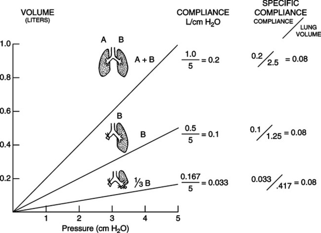
Q Specific compliance is a method of comparing the compliance of individuals of different sizes or different lung units in the same individual.
1. The formula for its determination takes into consideration the patient’s measured FRC or local end-expiratory lung volume.
2. Specific compliance (Cs) is equal to pulmonary compliance divided by the patient’s FRC (or local end-expiratory lung volume) and normally is equal to approximately 0.08 (dimensionless number):
 (3)
(3)3. Specific compliance can be determined for a lung segment or lobe (Figure 5-9).
A Airway resistance results from the movement of molecules of inspired gas over the surface of the airway.
B Airway resistance accounts for approximately 85% of nonelastic resistance to ventilation.
C Airway resistance (R) in laminar flow situations is equal to:
 (4)
(4)whereas in turbulent flow situations the relationship is:
 (5)
(5)D More than 60% of normal airway resistance is a result of turbulent gas flow through the nose, pharynx, and larynx.
E Resistance to gas flow decreases as gas moves into smaller generations of the airway. Because the cross-sectional area of the respiratory tract increases dramatically with increasing generations, flow through any single airway becomes progressively smaller. The pressure necessary to maintain flow decreases as airways become smaller because of the large airway surface area.
F At the level of the respiratory bronchioles, flow is almost absent, and gas movement basically is a result of diffusion.
G Airway resistance is increased when the lumen of the airway is decreased. The airway lumen is primarily decreased as a result of:
H Normal airway resistance is equal to approximately 0.6 to 2.4 cm H2O/L/sec when measured at a standard flow rate of 0.5 L/sec.
A The force necessary to overcome the inertia of the nonelastic structures of the lung-thorax system (i.e., bone, pleurae sliding over each other).
B Tissue viscous resistance accounts for approximately 15% of the nonelastic resistance to ventilation.
A The equation of motion is used to describe the interactions between the ventilator, respiratory muscles, and the patient:
 (6)
(6)B The elastic resistance of the respiratory system is determined by compliance (C) and tidal volume (VT), and the nonelastic resistance is determined by flow  and airway resistance (R).
 (7)
(7) (8)
(8)C As a result the equation of motion is normally written as:
 (9)
(9)D The equation of motion states that tidal volume, compliance, flow, and airway resistance determine the pressure required to deliver a breath.
E The pressure required to deliver a breath is a result of the combined pressure applied to the proximal airway (P airway) and the pressure generated by the respiratory muscles (P muscle):
 (10)
(10)F Thus, during spontaneous breathing all of the pressure needed to deliver a breath is provided by the respiratory muscles (P muscle); during assisted ventilation the pressure needed to deliver a breath is provided by a combination of the respiratory muscles (P muscle) and the ventilator (P airway); and during controlled ventilation all of the pressure needed to deliver a breath is provided by the ventilator (P airway).
G During volume ventilation, because flow and volume delivery from the ventilator are fixed, patient effort causes the airway pressure to decrease.
H During pressure ventilation, because airway pressure is fixed, patient effort causes the tidal volume to increase.
XI Functional Residual Capacity
A As stated previously, the thorax tends to expand, whereas the lung tends to collapse. At the FRC level, the vector forces of pulmonary and thoracic elastance are equal in magnitude and opposite in direction.
B The FRC is the most stable of all lung volumes and capacities because it is the level that is assumed when complete relaxation of ventilatory muscles occurs.
C If the elastance of the thorax and/or the lung were to increase or decrease, the volume of FRC would be altered.
XII Ventilation/Perfusion Relationships
A Distribution of ventilation is unequal because of:
1. Respiratory time constants:
a. If the compliance of the lung or part of the lung is multiplied by resistance of that part of the lung, a time constant is determined:
Compliance × Resistance = Time constant (11)
b. The time constant of a lung unit determines the amount of time it takes for the lung to fill or empty.
c. In healthy adults the respiratory time constant is approximately 0.25 second.
d. Approximately 3.5 to 4 time constants are required for inhalation or passive exhalation to be complete (Figure 5-10).
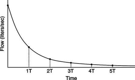
e. In the first time constant 63% of volume is delivered or exhaled.
f. In the second time constant 86.5% of volume is delivered or exhaled.
g. In the third time constant 95% of volume is delivered or exhaled.
h. In the fourth time constant 98.2% of volume is delivered or exhaled.
i. In the fifth time constant 99.3% of the volume is delivered or exhaled.
2. Regional variation in transpulmonary pressure in the respiratory tract:
a. In the standing position, the transpulmonary pressure gradient is greater in the apices than in the bases. As a result time constants are longer in the apices and shorter in the bases. The reasons for this variation are:
b. The transpulmonary pressure differences cause alveoli in the apices to contain a greater volume at FRC than alveoli in the bases.
c. Increases in the respiratory time constant increase the likelihood of air trapping and auto-positive end-expiratory pressure.
d. An increase in compliance or an increase in airway resistance increases the respiratory time constant.
e. Local time constants vary throughout the lung based on actual position.
f. These differences in alveolar size decrease as lung volume nears TLC.
3. As a result of differing transpulmonary pressure gradients and pulmonary time constants, when one inspires from FRC level:
a. Alveoli in the apices fill slowly and empty slowly (slow alveoli).
b. Alveoli in the bases fill rapidly and empty rapidly (fast alveoli).
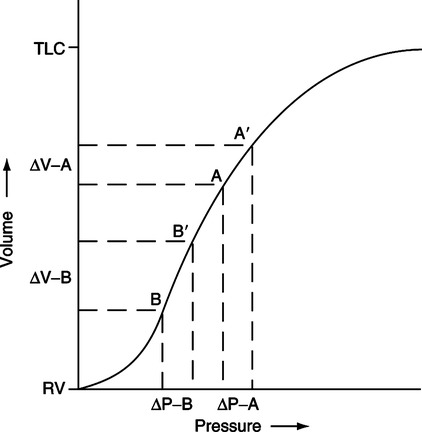
c. In normal tidal exchange most of the ventilation goes to the bases. Figure 5-11 illustrates the compliance curve of the total respiratory system. The position of the apices on the curve during tidal breathing is on the flatter aspect of the curve, whereas the bases are positioned on the steeper aspect of the curve. Points B to B′ indicate the volume change during normal ventilation in the bases; points A to A′ indicate the volume change during normal ventilation of the apices. There is a considerably larger volume change in the bases than in the apices per unit pressure change.
B Distribution of pulmonary blood flow normally is greater in the bases than in the apices.
1. Perfusion of any aspect of the lung depends on a number of factors, the relationship between local pulmonary hydrostatic pressure and the local transpulmonary pressure gradient, oxygenation-induced vasoconstriction, and local hormone levels.
2. Because the pulmonary vascular system is a low-pressure system, when standing the apices of the lung receive virtually no blood flow, whereas the bases are engorged with blood because of the effect of gravity.
3. In general, the most gravity-dependent aspect of the lung receives the majority of the blood flow, whereas the least gravity-dependent areas receive little or no blood flow, although this difference is greatly reduced in the prone position.
4. Basically, in the upright lung, three zones exist (Figure 5-12):
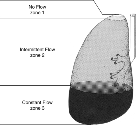
a. Zone 1: The extreme apex, where there is virtually no blood flow. Pulmonary vascular pressure is insufficient to overcome the effects of alveolar pressure compressing the blood vessels.
b. Zone 2: The remainder of the apex and middle part of the lung, where blood flow is intermittent. Here blood flow depends on the relationship between pulmonary artery pressure and alveolar pressure. When pulmonary artery pressure exceeds alveolar pressure, blood flow is present.
c. Zone 3: The bases, where blood flow is constant. Here blood flow is based on the difference between pulmonary artery and pulmonary venous pressures. A pulmonary artery catheter should always be placed in a Zone 3 blood vessel.
C Ventilation/perfusion ratios ( /
/ ratios).
1. The overall  /
/ ratio for the lung is 0.8.
2. In the apices the  /
/ ratio is approximately 3.3; in the bases it is approximately 0.6.
D Impact of position on gas exchange.
1. In healthy patients gas exchange is essentially unaffected by position.
2. In patients with ARDS in whom atelectasis and consolidation are common in the dependent lung when supine, positioning prone can be important.
3. Oxygenation is generally improved in the prone position in those with ARDS because the  /
/ ratios throughout the lung are less varied.
4. The distribution of ventilation and perfusion is not based solely on gravity (see Chapter 45).
XIII Ideal Alveolar Gas Equation
A In addition to the effects of Ph2o on the partial pressure of gases in the alveoli, the carbon dioxide diffusing from the bloodstream into the alveoli further decreases alveolar Po2.
B Because carbon dioxide is leaving the bloodstream, a closed system, and entering the respiratory tract, an open system, there is an indirect relationship between the alveolar pressures of carbon dioxide and oxygen. Increases in alveolar Pco2 result in decreases in alveolar Po2.
C This indirect relationship basically involves only carbon dioxide and oxygen because they are the only metabolically active gases.
D In addition, the amount of oxygen and carbon dioxide moving across the alveolar capillary membrane is unequal, 200 ml of carbon dioxide being produced for every 250 ml of oxygen consumed. Thus, the respiratory exchange ratio (R) CO2 produced divided by O2 consumed must be considered when estimating the alveolar Po2.
E The ideal alveolar gas equation is:
 (12)
(12)F A modification of equation (12) may be used for gross estimations of Pao2:
 (13)
(13)A Work associated with ventilation can be discussed from two perspectives:
B Metabolic cost of work of breathing:
1. The normal oxygen cost of breathing is low, approximately 5% of total oxygen consumption (5 ml O2/min or approximately 1 ml of O2/L of ventilation).
2. With mild to moderate increases in activity the oxygen cost of breathing is approximately 0.5 to 1.0 ml of O2/L of increased ventilation.
3. With marked increases in ventilation the oxygen cost of breathing can exceed 25% of total oxygen consumption and as a result limit overall activity.
4. With cardiopulmonary disease baseline oxygen cost of breathing may be >10% to 15% of total oxygen consumption, significantly limiting any increase in overall activity.
5. The more abnormal the airway resistance and compliance of the lung, the greater the increase in oxygen cost of breathing.
C Work (W) is defined as a force (F) applied to move an object a given distance (D):
 (14)
(14)D Thus, regardless of energy expenditure, no work is performed unless movement occurs.
E This relationship can be applied to the respiratory system because pressure (P) is a force per unit area and volume (V) represents a distance:
 (15)
(15)F Total mechanical work is equal to lung work plus chest wall work.
G Measurement of total mechanical work is illustrated in Figure 5-13.
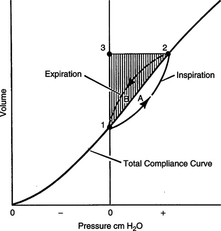
H For measurement of total work, the lung-thorax system must be inflated with positive pressure in an apneic individual.
1. During inflation, pressure change in the airway or at the mouth is measured, as is VT, and plotted against each other (see Figure 5-13).
2. Tidal ventilation is represented by the vertical distance 1 to 3, whereas pressure required to maintain thoracic expansion is represented by the horizontal distance 3 to 2.
3. The shaded triangle 1, 2, and 3 plus area A indicate the total mechanical work.
4. The shaded areas 1, 2, and 3 depict work required to overcome elastic forces.
5. Work required to overcome nonelastic forces is depicted by area A.
6. Work required to overcome inertial forces cannot be separated from elastic and nonelastic work by this method.
7. The elastic and nonelastic workloads are always additive.
8. Elastic work of inspiration is stored in the elastic structures of the thoracic cavity, whereas nonelastic work cannot be stored.
9. Nonelastic forces also are active only during gas movement.
10. Exhalation is normally passive as long as the work of exhalation does not exceed the stored elastic work. Area B is the nonelastic work required during passive exhalation. Exhalation will become active if the area of B exceeds the shaded areas 1, 2, and 3, which represent the elastic work stored during inspiration.
I Figure 5-13 would also represent the work of the lung if the pressure gradient used were the transpulmonary pressure because the pleural pressure change represents the pressure required to move the lung.
J Chest wall work (WOBC) is not normally directly measured. It is usually calculated from lung work (WOBL) and total mechanical work (WOBT):
 (16)
(16)K During spontaneous unassisted breathing only lung work can be measured.
1. To measure lung work of breathing an esophageal balloon needs to be placed to reflect pleural pressure change.
2. Esophageal pressure is compared with atmospheric pressure to determine transpulmonary pressure change during normal tidal volume breathing.
3. Figure 5-13 also represents the methodology to determine spontaneous work of breathing of the lung.
a. All that needs to be done is to reverse the signs on the pressure axis.
b. To the right of zero the pressure would be negative, and to the left the pressure would be positive.
c. During spontaneous inspiration esophageal pressure became more negative compared with baseline and tidal volume increases.
4. To measure total work of breathing and calculate chest wall work, the patient would have to be intubated, heavily sedated, and mechanically ventilated.
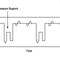
1. Another approach to evaluate patient effort during spontaneous breathing or assisted ventilation is to determine the area of the esophageal pressure-time curve during inspiration.
2. The larger the area the greater the effort.
3. The value determined frequently is used to compare one set of circumstances (different levels of pressure support) with another set of circumstances.
4. The pressure-time product is also used to evaluate the effort to trigger the ventilator during assisted ventilation. In this setting either airway pressure versus time or esophageal pressure versus time is evaluated.
M The following are normal values for total lung and chest wall work in healthy individuals:
| Joules/L | kg × m/L | |
| WOBT | 0.07-0.10 | 0.70-1.0 |
| WOBL | 0.035-0.05 | 0.35-0.5 |
| WOBC | 0.035-0.05 | 0.35-0.5 |
N Workloads are also expressed for a 1-minute period. This is normally referred to as a representation of ventilatory power. If minute volume were equal to 6 L, the following values for power in kg × m/min and joules/min would be noted in normal adults:
| Joules/min | kg × m/min | |
| Total ventilatory power | 0.42-0.60 | 4.2-6.0 |
| Lung power | 0.21-0.30 | 2.1-3.0 |
| Chest wall power | 0.21-0.30 | 2.1-3.0 |