Modes of Mechanical Ventilation
I Pressure and Volume Targeting (Table 39-1)
TABLE 39-1
Pressure- Versus Volume-Targeted Ventilation
| Pressure | Volume | |
| Peak airway pressure | Constant | Variable |
| Peak alveolar pressure | Constant | Variable |
| Tidal volume | Variable | Constant |
| Peak flow | Variable | Constant |
| Flow pattern | Decelerating | Preset |
| Inspiratory time | Preset | Preset |
| Minimum rate | Preset | Preset |
A Regardless of terminology used to identify a mode of ventilation, all modes operate by targeting pressure, volume, or both of these variables.
B With volume targeting, a specific volume of gas is delivered each tidal volume (Vt). As a result
2. Peak flow or inspiratory time must be selected.
3. A gas flow pattern must be set.
a. Square wave and decelerating wave flow patterns are available on current generation ventilators (Figure 39-1).
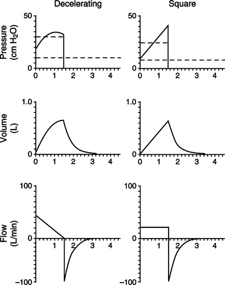
b. With square wave flow, the set flow is constant throughout inspiration.
c. With a decelerating wave flow pattern, the flow decreases from the maximum set flow to a minimal end-inspiratory flow.
d. The minimal flow in decelerating wave is variable from ventilator to ventilator and in some ventilators can be adjusted.
e. The flow waveform affects peak flow and the inspiratory time required to deliver a given Vt.
f. If the peak flow is constant, inspiratory time must be longer with a decelerating flow pattern than with a square wave flow pattern.
g. If inspiratory time is constant, peak inspiratory flow must be higher with a decelerating flow pattern than with a square wave flow pattern.
h. When changing flow pattern care must be exercised to ensure that proper peak flow or inspiratory time is set.
4. Pressure is the resultant variable, and it can vary considerably from breath to breath.
C With pressure targeting, maximum preset peak airway pressure is set, and this limits peak alveolar pressure to the set level. As a result
1. Maximum airway and alveolar pressures are targeted.
2. Vt can vary from breath to breath.
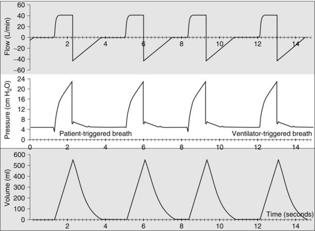
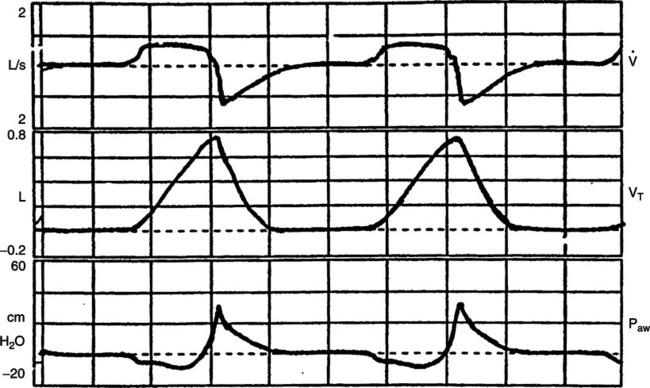
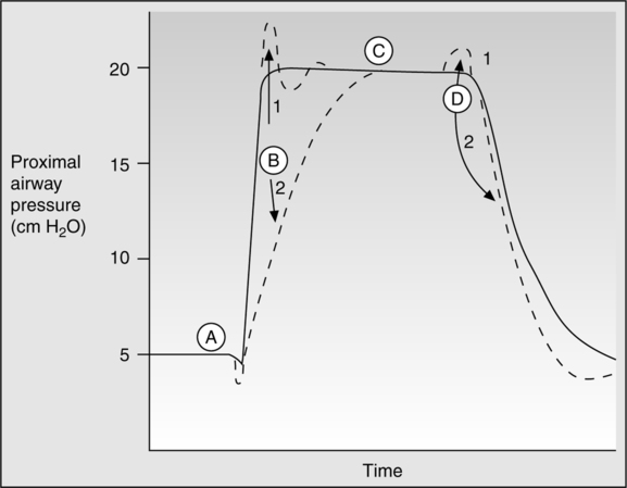
3. Gas flow delivery is variable (Figure 39-2).
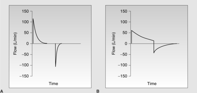
a. A high initial flow is delivered. The rate of initial flow delivery is based on set peak pressure, the patient’s lung mechanics, and patient demand.
b. Peak flow must rapidly decrease as the target pressure is reached to prevent pressure from exceeding the target level.
(1) The higher the set pressure, the higher the initial flow.
(2) The higher the patient demand, the greater the initial flow.
(3) The higher the resistance and the lower the compliance, the lower the initial flow.
c. To prevent pressure from exceeding the target, flow may decrease to zero before the end of inspiration.
d. Inspiratory time may be set or the breath may end when inspiratory flow decreases to a predetermined level.
D With pressure and volume combined targeting modes, the ventilator attempts to ensure a preselected maximum pressure is never exceeded and a preselected Vt is delivered.
1. Gas delivery is usually in a pressure-targeting format but may change to a volume format during the breath in some modes.
2. A high initial flow is delivered that rapidly decelerates over time.
3. System pressure is maintained below the maximum selected but may change on a breath-to-breath basis to ensure that the Vt selected is delivered.
E In all of these different gas delivery formats
F Pressure- and volume-targeted breaths respond differently to changes in compliance and resistance of the respiratory system (Table 39-2).
TABLE 39-2
Effect of Changing Compliance and Resistance During Pressure and Volume Ventilation
| Pressure | Volume | |
| Decreased compliance | ↓ Volume | ↑ Pressure |
| Increased compliance | ↑ Volume | ↓ Pressure |
| Increased auto-PEEP | ↓ Volume | ↑ Pressure |
| Decreased auto-PEEP | ↑ Volume | ↓ Pressure |
| Pneumothorax | ↓ Volume | ↑ Pressure |
| Bronchospasm | ↓ Volume | ↑ Pressure |
| Mucosal edema | ↓ Volume | ↑ Pressure |
| Secretions | ↓ Volume | ↑ Pressure |
| Pleural effusion | ↓ Volume | ↑ Pressure |
| Increased patient effort | ↑ Volume | ↓ Pressure |
| Decreased patient effort | ↓ Volume | ↑ Pressure |
1. Any factor that increases resistance or decreases compliance during volume ventilation causes the peak airway and peak alveolar pressure to increase.
2. Any factor that decreases resistance or increases compliance during volume ventilation causes the peak airway and peak alveolar pressure to decrease.
3. Any factor that increases resistance or decreases compliance during pressure ventilation causes VT to decrease.
4. Any factor that decreases resistance or increases compliance during pressure ventilation causes VT to increase.
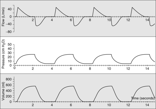
G During pressure and volume ventilation, effective static compliance can be measured if a static condition is achieved (Figure 39-3).
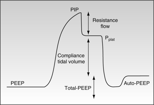
1. With volume ventilation an end-inspiratory pause is set, allowing all airflow to cease. Effective total respiratory system compliance is calculated by:
< ?xml:namespace prefix = "mml" />
 (1)
(1)a. Volume compressed in the ventilator circuit must be subtracted from the ventilator set volume to identify the actual Vt entering the airway. Some ventilators automatically correct for compressed volume in the ventilator circuit. Normally approximately 1 to 2 ml/cm H2O plateau pressure minus total PEEP is compressed in the ventilator circuit.
b. Total PEEP (applied plus any additional auto-PEEP) is subtracted from the plateau pressure to ensure that only the actual pressure needed to maintain the Vt in the lung is identified.
2. During pressure ventilation, compliance can be calculated if the flow rate returns to zero 200 to 300 msec before the end of the breath (see Figure 39-2, A). If this occurs the set pressure level is equal to the plateau pressure, which is equal to the average peak alveolar pressure.
 (2)
(2)H Estimation of airway resistance can be determined during volume ventilation but not pressure ventilation (see Figure 39-3).
1. To calculate airway resistance during mechanical ventilation, a constant gas flow rate must be provided.
2. Constant flow (square wave) is only possible during volume ventilation.
3. When flow is constant the pressure difference between the peak pressure and the plateau pressure is the pressure required to overcome airway resistance.
 (3)
(3)A All modes of ventilation on current generation ventilators allow the patient to trigger (activate) gas delivery.
B Controlled ventilation, the absence of patient active interaction with the ventilator, can only truly be established by sedating the patient to apnea.
C The sensitivity control on ventilators allows the clinician to determine the amount of patient effort required to trigger a ventilator-assisted breath.
D Even at sensitivity settings requiring large inspiratory efforts, patients with strong ventilatory demands can trigger a breath.
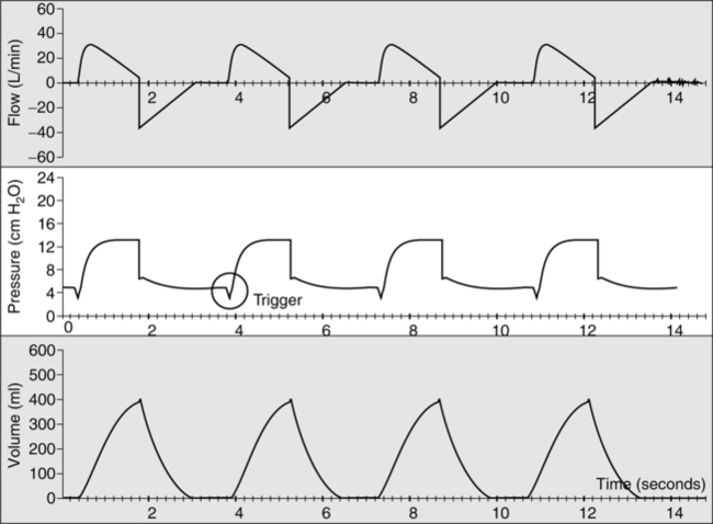
E Ventilator triggering can occur by two mechanisms: change in pressure or flow (Figure 39-4).
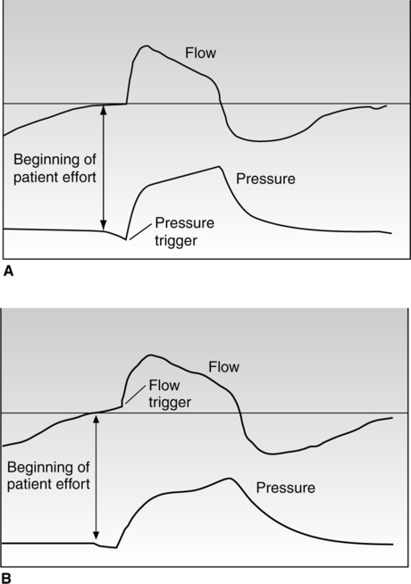
1. Traditionally all ventilator modes were pressure triggered.
2. To activate a breath the patient had to decompress the ventilator circuit a sufficient level to overcome the sensitivity setting.
3. The major problem with pressure triggering is the location of pressure sensing.
a. If pressure is sensed at the ventilator, pressure at the wye of the ventilator circuit must be less than that measured at the ventilator.
b. If the sensitivity is set at −2 cm H2O the patient may have to establish a −4 cm H2O pressure at the wye.
c. If pressure is measured at the circuit wye this concern is eliminated.
d. With pressure triggering pressure changes before flow is provided.
e. During flow triggering either the patient must divert a set flow from a low continuous flow or generate a specific flow through a pneumotachograph placed at the airway.
f. As a result of the design of flow-triggered systems they tend to minimize effort to a greater extent than pressure triggering.
g. With flow triggering flow is established before the ventilator generates airway pressure.
h. Less effect is required to trigger a ventilator set at 2 L/min flow triggering versus −2 cm H2O pressure triggering.
i. Regardless of the trigger available on a given ventilator, trigger sensitivity should always be set as sensitive as possible to avoid auto-triggering and to minimize patient effort.
j. With pressure triggering, water in the ventilator circuit tends to increase auto-triggering.
k. With flow triggering, leaks in the system tend to increase auto-triggering. This also occurs in pressure triggering when PEEP is set.
l. All factors being equal, flow triggering seems to be the most efficient method of triggering a breath.
A This mode of ventilation can be provided in pressure and volume targeting (Figures 39-5 and 39-6).
B The basic operation is that every breath is a positive-pressure breath triggered by the patient.
C If the patient does not trigger the breath, the ventilator automatically delivers a back-up breath (controlled breath).
D Volume-targeted assist/control (AC) mode is the most common mode of ventilation used worldwide.
E During volume AC the following variables must be set.
a. Setting of peak flow along with Vt and flow waveform determines the inspiratory time.
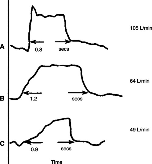
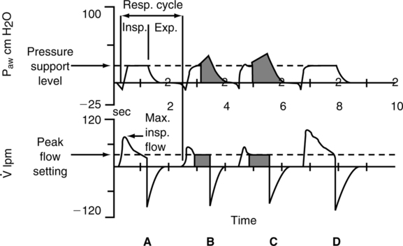
b. Peak flow in assisted ventilation is set to meet patient’s inspiratory flow demand (Figure 39-7). If peak flow is set too low, patients may be required to perform a large amount of the work of breathing.
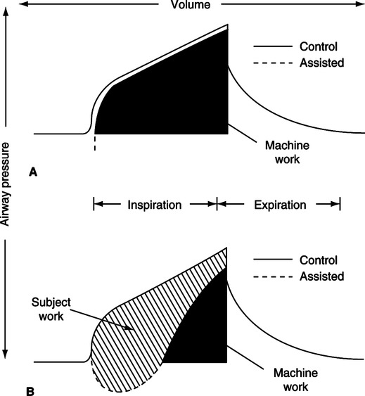
c. Figure 39-7 depicts the airway pressure waveforms during controlled and assisted ventilation in a patient with all ventilator settings constant.
d. During controlled ventilation the area under the airway pressure curve is equal to the total work required to ventilate a patient.
e. During assisted ventilation the same amount of work must be done, but the patient now shares the work.
f. As a result the area in Figure 39-7 (bottom) identified as subject work can be high if the peak flow is inadequate.
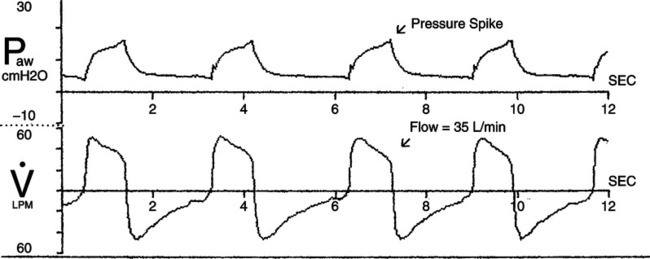
g. Figure 39-8 indicates an airway pressure waveform in which the peak flow is grossly inadequate, indicating excessive patient work.
 ), and volume (Vt) waveforms during volume-targeted ventilation. The Paw grossly illustrates inadequate peak inspiratory flow. This patient’s work of breathing is excessive despite ventilatory assistance. The peak flow needs to be markedly increased.
h. The more the actual airway pressure waveform deviates from the expected airway pressure waveform (see Figure 39-8), the greater the work performed by the patient.
i. Peak flow frequently needs to be set ≥80 L/min to meet patient peak inspiratory demands and minimize the work of breathing.
4. Inspiratory time (set on some ventilators)
a. During assisted ventilation patients usually require an inspiratory time ≤1.0 seconds.
b. It is unusual for spontaneously breathing patients to desire an inspiratory time >1.0 second.
c. During controlled ventilation inspiratory time can be lengthened (see inverse ratio ventilation).
6. In some ventilators the inspiratory to expiratory (I:E) ratio is set.
a. The I:E ratio is the relationship between inspiratory and expiratory time.
b. During normal breathing I:E ratios are approximately 1:2.
c. In patients with obstructive lung disease I:E ratios are smaller, 1:3 to 1:6 or more.
d. Most do not set I:E ratio, preferring to set inspiratory time directly or indirectly by setting peak flow and rate.
F Pressure AC essentially functions the same as volume AC except by pressure targeting.
G During pressure AC the following variables must be set.
4. With some units I:E can be set.
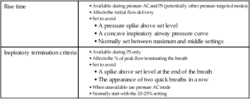
8. Rise time (see later section)
a. Inspiratory time is usually ≤1.0 seconds in patients actively triggering the ventilator.
b. It is unusual for patients to desire an inspiratory time >1.0 second when spontaneously breathing.
c. During control ventilation inspiratory time can be lengthened; however, it is questionable whether this is beneficial (see inverse ratio ventilation).
IV Synchronized Intermittent Mandatory Ventilation
A Figure 39-9 illustrates a typical volume-targeted square wave flow synchronized intermittent mandatory ventilation (SIMV) breath.
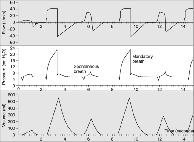
B With this mode of ventilation a mixture of spontaneous and mechanically assisted breaths is provided.
C SIMV can be provided using volume- or pressure-targeted ventilation for the mandatory breaths.
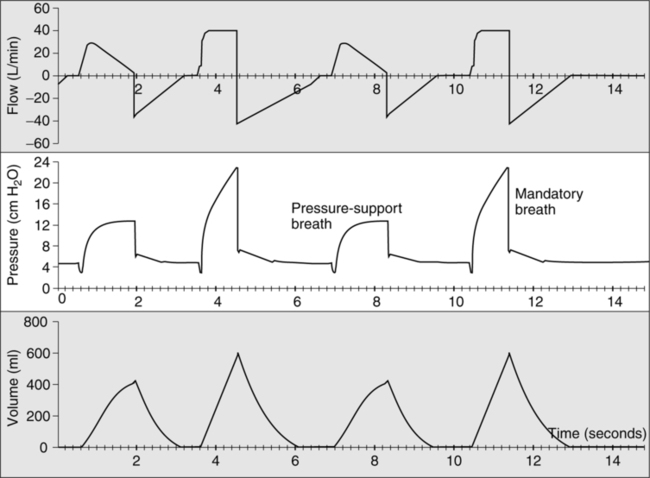
D During the spontaneous breaths pressure support (PS; see Section VI, Pressure Support) can be added (Figure 39-10).
E In SIMV a mandatory rate is set and provided in an AC format. However, only the set number of mandatory breaths is provided.
F In between these breaths spontaneous effort by the patient does not trigger a mandatory breath.
G However, as noted previously PS may be added to provide assistance between the mandatory breaths.
H If a mandatory rate of 10 is set every 6 seconds, the ventilator will apply a mandatory breath. The breath is an assisted (patient-triggered) breath if the patient makes an inspiratory effort within the 1- to 2-second window of time set aside to allow patient triggering.
I If the breath is not triggered in the allotted time a controlled breath is delivered.
J The goal is to only provide partial ventilatory support, allowing the patient to perform a varying level of breathing effort.
K As noted in Figure 39-11 there is a difference in the distribution of ventilation during unassisted breaths and mechanical breaths that favors improved ventilation to perfusion matching during unassisted spontaneous breathing.
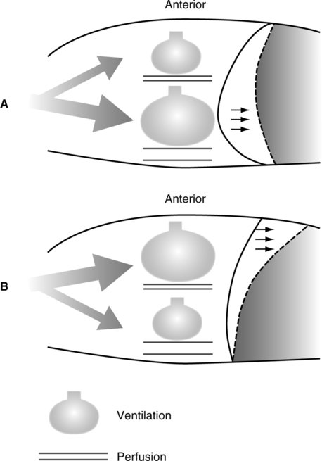
L Spontaneous breathing also improves venous return and, as a result, cardiac output.
M Many believe patients also are less likely to hyperventilate to alkalosis with SIMV than AC.
N Increased work of breathing is of major concern with SIMV at moderate and lower mandatory rates.
1. Figure 39-12 depicts the impact of decreasing the mandatory rate on patient work of breathing.
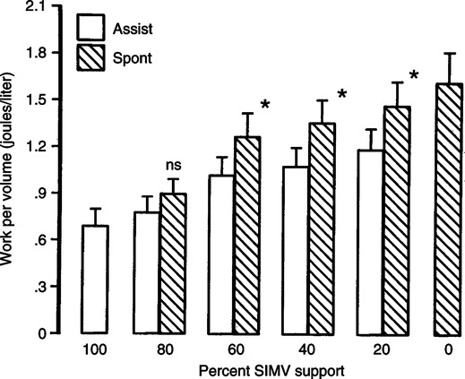
2. As noted when the mandatory rate is decreased, work of breathing increases for the spontaneous and mandatory breaths.
3. The work of breathing during the mandatory breath can be high at moderate and lower mandatory rates.
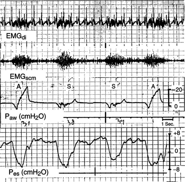
4. Figure 39-13 illustrates the change in esophageal pressure during moderate rate SIMV, demonstrating equal pressure change with spontaneous and mandatory breaths and thus equal patient effort.
5. When the SIMV mandatory rate is <70% to 80% of the total respiratory rate, concern about patient effect should be raised.
O In the United States SIMV is as popular a mode as AC. However, the rest of the world rarely uses the SIMV mode in adults.
P During SIMV the following variables should be set.
2. Peak flow (volume targeted only)
3. Flow waveform (volume targeted only)
4. Pressure level (pressure targeted only)
5. Inspiratory time (always with pressure targeted and on some ventilators with volume targeting)
11. Rise time (pressure targeted only)
12. Inspiratory termination criteria (pressure-supported breaths only, see Section VI, G, Inspiratory Termination Criteria)
V Intermittent Mandatory Ventilation
A This is similar to SIMV except all mandatory breaths are control breaths, and PS cannot be added to the spontaneous breaths.
B During spontaneous breathing a continuous flow of gas is provided.
C Intermittent mandatory ventilation (IMV) is not available on modern ventilators.
D In addition to the problems with SIMV, during IMV the mandatory breath could be stacked on top of the spontaneous breath, increasing dyssynchrony and increasing intrathoracic and intracranial pressure.
E Similar to SIMV all the described variables are set except
A PS is one of the modes of ventilation that allow the patient a significant level of control over the application of ventilatory support.
B The pressure, flow, and volume waveforms (Figure 39-14) during PS are the same as during pressure AC.
C The only variable that differs is the mechanism that terminates the breath.
1. In pressure AC the breath ends when the set inspiratory time is reached; with PS the primary mechanism ending the breath is flow (Table 39-3).
TABLE 39-3
Criteria for Terminating a Pressure Support Breath
| 1° Mechanism | |
| 2° Mechanism | |
| 3° Mechanism |
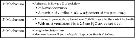
2. A PS breath ends when flow has decreased to a predetermined percentage of the peak flow.
3. With most ventilators the termination flow percentage is fixed at 25%.
4. Some ventilators allow the inspiratory terminating flow to be adjusted (see Section VI, G, Inspiratory Termination Criteria).
5. The secondary terminating criterion is pressure. With all ventilations if the pressure exceeds the set level after the first 200 to 300 ms of inspiration, the breath is ended. The magnitude of the pressure increase varies from ventilator to ventilator but is usually 2 to 5 cm H2O above set level.
6. The third factor that will terminate a PS breath is time. After 2 to 3 seconds of inspiratory time, all ventilators will automatically end the breath.
D A backup rate is not set in most ventilators during PS; however, all new generation ventilators allow the setting of apnea ventilation, a controlled gas delivery pattern that takes over in the presence of apnea.
E During PS the following variables are set.
TABLE 39-4
Rise Time and Inspiratory Termination Criteria
| Rise time | |
| Inspiratory termination criteria |
1. Figure 39-15 illustrates the potential problems with gas delivery that can cause dyssynchrony during PS.
a. At the onset of a pressure-targeted breath, gas can be delivered too rapidly or too slowly compared with patient demand. Either can cause dyssynchrony.
b. At the termination of the breath, the breath can end before the patient is ready to end the breath or the patient can desire to exhale before the ventilator is ready to allow the patient to exhale.
2. The effect of changing rise time is illustrated in Figure 39-16.
a. Essentially rise time alters the slope of the airway pressure rise by changing the time needed for flow to increase to its maximum level.
b. A rapid rise time ensures that flow will be delivered quickly at the start of the breath, causing pressure to almost immediately rise to the set level.
c. A slow rise time decreases the rise in flow to its maximum level, and as a result pressure may not reach the set level until late in the breath.
d. As illustrated in Figure 39-15, rise time should be set to ensure pressure rises rapidly in a linear manner but does not exceed the set level at the beginning of inspiration.
e. An inadequate rise time can result in a concave airway pressure curve similar to that in Figures 39-7 and 39-8.
f. Too rapid a rise time causes pressure to exceed the set level at the onset of the breath.
g. With a rapid rise time, peak flow increases and inspiratory time tends to shorten (see Figure 39-16).
3. Rise time is operable on most ventilators during pressure AC and PS but could be functional on any mode that uses a pressure-targeted gas delivery format.
G Inspiratory termination criteria, inspiratory cycling criteria, or expiratory sensitivity (see Table 39-4)
1. As noted previously terminology regarding this control only available on PS varies from ventilator to ventilator.
2. As discussed in Figure 39-15 at the end of a PS breath, pressure should decrease linearly from the set level to PEEP.
3. When the patient’s desire to end a breath and the ventilator settings to end the breath do not match, dyssynchrony occurs.
4. Figure 39-17 illustrates the patient desiring to end the breath before the ventilator flow has decreased to the terminating level.
5. The increase in pressure at the end of the breath above set level (see Figure 39-17) is a result of activation of accessory muscles of exhalation during the end of the ventilator’s inspiratory phase.
6. This causes the pressure to increase above set level cycling to expiration by the 2nd degree cycling mechanism, an increase in end-inspiratory airway pressure.
7. When this happens the patient’s ventilatory drive is increased, and his or her respiratory rate increases.
8. Adjustment of the inspiratory cycling criteria can correct this problem.
9. A higher percent cycling criteria should be set by slowly increasing the setting and observing the response. When the pressure spike is eliminated the termination criteria are set correctly.
10. Figure 39-18 illustrates the opposite problem, the patient desiring to continue inspiration after the ventilator has cycled to exhalation.
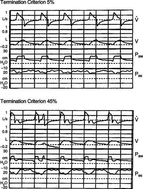
 ), volume (V), airway pressure (Paw), and esophageal pressure (Pes) curves with termination criterion (TC) 5% and TC 45% during 10 cm H2O of pressure support ventilation. With TC 5%, inspiratory flow terminated simultaneously with the cessation of the patient’s inspiratory effort estimated by Pes. In contrast, premature termination with double breathing occurred with TC 45%. Work of breathing also increased from 0.42 J/L with TC 5% to 0.64 J/L with TC 45%.
11. Note the second bump in the airway pressure and flow waveform on Figure 39-18, bottom. These indicate continued inspiratory effort before the patient begins exhalation after the ventilator ends the breath.
12. In this setting the termination criteria should be set at a lower percentage to lengthen the ventilator inspiratory time (see Figure 39-18, top).
13. Inspiratory termination criteria should be initially set at 20% to 25% and then adjusted to meet the patient’s needs.
14. If inspiratory termination criteria is not available on a particular ventilator and problems with cycling to exhalation exist, change the patient to pressure AC.
a. In pressure AC all gas-delivery features are the same as with PS except the ending of the breath.
b. Set the inspiratory time equal to the patient’s desired inspiratory time; remember this will most likely be <1.0 second.
c. Set the backup rate at a level that will not affect the patient’s control of the rate; usually 10 breaths/min is adequate.
15. When correct termination criteria are set, patient-ventilator dyssynchrony is eliminated, and respiratory rate frequently decreases.
16. The two ventilators in which inspiratory termination dyssynchrony during PS is most common are the Puritan Bennett 7200 (cycling criteria, 5 L/min) and the Servo 300 (cycling criteria, 5%) because of their low and nonadjustable cycling criteria.
17. Patients with chronic obstructive pulmonary disease (COPD) are most likely to experience problems with inspiratory termination during PS because they tend to desire to end inspiration with a flow that is relatively high. Adjustment of the termination criteria has the greatest impact on COPD patients.
H PS is a useful mode in many clinical settings. Of primary concern is the patient’s ventilatory drive. If it is intact, PS may be used to provide ventilatory support to most spontaneously breathing patients.
VII New Modes of Mechanical Ventilation
A Box 39-1 lists the six modes of ventilation that are considered by most as new modes of ventilatory support.
B AC, SIMV, and PS have been available for >20 years on most mechanical ventilators and have a large database of information from which to draw material about their use.
C The new modes have only been available for a short period, and for many only limited information on their use is available except from the manufacturer.
D All of these modes in the broadest sense incorporate some level of computerized control of ventilation.
1. A range of variables is set, but the ventilator is able to change gas delivery based on evaluation of changes in various measured variables.
2. In some modes ventilatory support can go from near controlled ventilation to continuous positive airway pressure (CPAP).
E Most of these modes use a pressure-targeted ventilation format to delivery gas during at least part of the inspiratory cycle.
F As indicated in Box 39-1 these modes can be divided into two groups, depending on how adjustment to gas delivery is accomplished.
1. Within-breath adjustments: As the patient is ventilated the ventilator assesses gas delivery and adjusts delivery during the breath.
2. Between-breath adjustments: The ventilator evaluates gas delivery during the current breath and makes adjustments to delivery on the next breath.
G Pressure-regulated volume control (PRVC), pressure control plus, auto flow, and so on
1. Many terms are used by various manufacturers to indicate this between-breath adjustment mode.
2. The airway pressure, flow, and volume waveforms on a given breath are exactly the same as with pressure AC.
3. This mode differs from pressure AC by adjusting the pressure level on a breath-to-breath basis to ensure a targeted Vt is delivered.
4. With this mode the following must be set.
5. When applied to a patient the ventilator gives a few test breaths at a low-pressure level and calculates the pressure setting required to delivery the Vt.
6. The ventilator then applies a higher-pressure setting near 60% to 80% of the required level to achieve the targeted Vt, reassessing its calculation.
7. The ventilator then will deliver the pressure level required to deliver the Vt.
8. For each breath the ventilator assesses the Vt delivered.
9. If Vt is low, on the next breath the pressure is increased, usually between 1 and 3 cm H2O, and the Vt is reassessed.
10. If Vt is high, on the next breath the pressure level is decreased usually between 1 and 3 cm H2O, and the Vt is reassessed.
11. The pressure level may be adjusted for every breath if there is a lot of variability in the Vt.
12. Pressure can be increased to the maximum target set and can be decreased in some ventilators to PEEP level.
13. In no ventilator is there currently the ability to set a lower pressure limit.
14. This mode is capable of ensuring the target Vt is delivered using a pressure ventilation format.
15. It is used by many in settings in which variation in Vt is large, and concerns exist about the patient being allowed to inhale a large Vt during a pressure-targeted breath.
16. This mode works best in patients who are apneic or have a weak ventilatory drive.
17. Significant concern should be exercised for patients with a high ventilatory demand because any stimulus that would increase ventilatory demand causing an increased Vt results in a decrease in inspiratory pressure.
a. If this stimulus is sufficient, pressure could decrease all the way to the PEEP level.
b. A patient markedly stressed with a high ventilatory drive may not receive any ventilatory support.
18. The addition of a minimum pressure limit adjustable by the clinician would greatly improve the safety of this mode.
H Volume support and volume guarantee
1. This mode operates the same as PRVC except on a PS format.
2. All comments related to PRVC are also accurate for volume support.
3. During volume support the following variables must be set.
I Adaptive support ventilation
1. This mode of ventilation is only available on Hamilton ventilators.
2. This is a between-breath adjustment mode that is used in conjunction with other modes of pressure-targeted ventilation: pressure AC, PS, and SIMV.
3. It is a mode designed to ensure that the ventilatory pattern is one that results in the least work of breathing.
4. This is accomplished by the setting of the following variables.
5. The ventilator calculates ideal minute volume as 0.1 L/min/kg.
6. The percentage of ideal minute volume to be ensured can be any valve ≤200%.
7. Five test breaths are delivered to define dynamic compliance and the expiratory time constant.
8. The ventilator then calculates the Vt and rate that will result in the least work of breathing.
9. The ventilators follow an algorithm essentially with four gradients designed to adjust the respiratory rate and peak inspiratory pressure to move the respiratory pattern to the ideal Vt and rate.
a. Measure Vt increased, rate decreased
b. Measured Vt decreased, rate decreased
10. Few data are available to evaluate the effect of this mode.
11. From a theoretical perspective it seems an interesting approach to maintaining a ventilatory pattern that minimizes work of breathing.
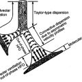
J Automatic tube compensation (ATC)
1. This within-breath adjustment mode of ventilation can be used by itself or during the spontaneous breaths of SIMV and bilevel pressure ventilation (see Section X, Bilevel Pressure Ventilation).
2. It is designed to apply sufficient pressure to eliminate the flow-resistant work of breathing imposed by the endotracheal tube.
3. Essentially it attempts to maintain the pressure at the tip of the endotracheal tube equal to the end-expiratory baseline pressure.
4. This is accomplished by applying a varying level of positive pressure during inspiration and a varying level of negative pressure during exhalation.
5. The level of pressure applied is based on the ventilator knowing the exact airway size (tracheostomy or endotracheal) and instantaneous changes in flow.
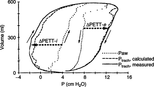
6. As noted in Figure 39-19 with this information the pressure at the tracheal level can be calculated, and as a result the correct pressure is applied to minimize tracheal pressure change.
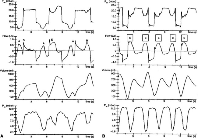
7. Figure 39-20 illustrates the effect of ATC in a COPD patient with a high demand and a postoperative patient with a low ventilatory demand.
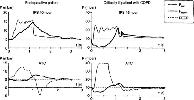
8. ATC is most effective in reducing resistive effort in COPD patients because of their high demand, requiring greater pressure than originally applied with PS (see Figure 39-19).
9. As noted in the example of the postoperative patient (see Figure 39-20), the applied pressure peaks at the onset of the breath but decreases at the end of the breath because ventilatory demand decreases.
10. Ventilators with this mode may allow ATC to be used only during inspiration or during inspiration and expiration.
11. Use during expiration is a concern for patients with airway obstruction (e.g., COPD, asthma) because the negative airway pressure may increase air trapping.
12. There are no specific indications for the use of ATC, but it appears it may be useful to identify the PS level needed to overcome the resistance of the endotracheal tube.
13. Others have proposed the use of ATC during weaning. When patients are able to adequately ventilate with a low ATC level, they are considered ready to be extubated.
14. However, there are no outcome data indicating more rapid weaning.
K Volume assured PS (VAPS) or pressure augmentation
1. Similar to ACT, VAPS is a within-breath adjustment mode that can be considered a dual mode of ventilatory support.
2. This mode is designed to reduce the work of breathing while maintaining a minimum minute volume and a minimum Vt.
3. This mode combines the high initial flow of a pressure-targeted breath with the constant volume delivery of a volume-targeted breath.
4. With VAPS the following variables are set.
5. When the ventilator is triggered, the initial pressure target is the PS level (Figure 39-21).
6. However, if the targeted volume is not delivered before flow is decreased to the inspiratory cycling criteria, the breath changes from a pressure-targeted to a volume-targeted breath.
7. The remainder of the breath becomes a volume-targeted breath.
8. If the patient’s demand is high and the targeted Vt can be delivered before the PS termination criteria are met, the breath continues as a PS breath only.
9. If the targeted Vt cannot be delivered (e.g., a patient with a weak ventilatory drive), the breath rapidly converts to a volume-targeted breath, ensuring the minimal Vt delivery.
10. Essentially gas delivery always begins as a PS breath but changes to a volume-targeted breath if the target Vt is not reached before the PS inspiratory termination criteria are met.
11. This mode ensures a minimum Vt is delivered in a partial PS format. It also allows access to additional volume and flow if a patient’s ventilatory demand is high.
L Proportional assist ventilation (PAV)
1. This is the most unique within-breath adjustment mode of ventilatory support available.
2. With PAV there are no controls over gas delivery.
3. Airway pressure is provided based on patient demand. The higher the demand, the higher the level of pressure applied; the lower the demand, the lower the level of pressure applied.
4. The level of support provided is determined by setting the percentage of elastic and resistive work that will be unloaded.
5. A schematic of the operation of PAV is depicted in Figure 39-22.
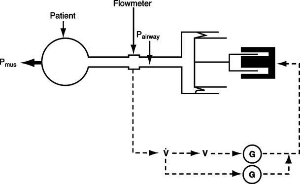
 , Instantaneous flow. V, Instantaneous volume. G, Gain control.
6. As noted the percentage of flow unloading and volume unloading is set by adjusting gain controls affecting volume and flow response.
7. A comparison of the impact of PAV versus other modes is illustrated in Figure 39-23.
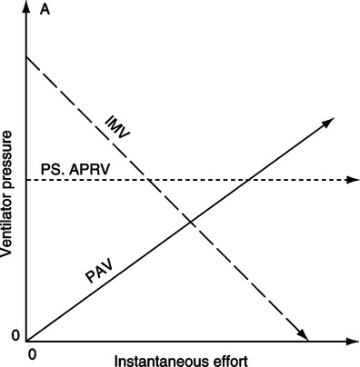
8. With PAV, support increases as demand increases, whereas with volume-targeted ventilation (e.g., SIMV), support decreases as demand increases, and with pressure targeting, support stays constant regardless of demand.
9. A major problem with PAV is runaway, an unlimited application of airway pressure.
10. To avoid runaway requires precise measurement of compliance and resistance on an ongoing basis.
11. It is important to remember with PAV a patient may chose a ventilatory rate of 50 breaths/min and a Vt of 100 ml or a rate of 5 breaths/min with a Vt of 1.0 L.
12. Currently there are no established indications for PAV, but it does seem to provide ventilatory support during noninvasive positive pressure ventilation as well as PS.
VIII Inverse Ratio Ventilation
A This approach is just what the title implies: exhalation is longer than inspiration.
B Ideally exhalation is short enough to cause air trapping and auto-PEEP, whereas inspiration is long enough to allow uniform distribution of inspiration.
C Typically this approach is applied using pressure AC; however, volume ventilation may also be used.
D Because of the inverse ratio and the design of ventilators, at the time of the introduction of the mode patients required heavy sedation, and frequently neuromuscular paralysis is needed for the mode to be applied.
E Inverse ratio ventilation (IRV) does improve oxygenation but does not have any advantages over normal I:E ventilation with appropriately applied PEEP.
F IRV has the disadvantage of markedly increasing mean airway pressure, which frequently results in hemodynamic compromise.
G IRV is only useful for patients with severe acute respiratory distress syndrome.
IX Airway Pressure Release Ventilation
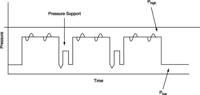
A Airway pressure release ventilation (APRV) is similar to IRV and SIMV except the patient is allowed to inspire and exhale at the high-pressure setting and low-pressure setting (Figure 39-24).
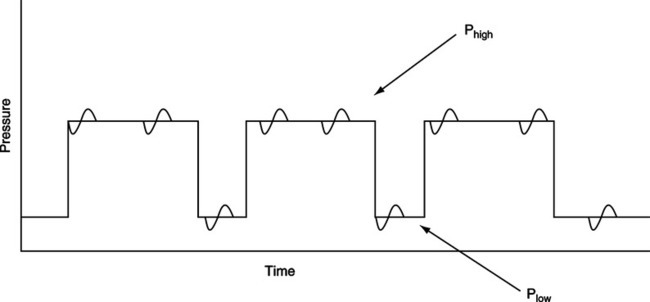
B This mode is frequently considered as the application of two levels of CPAP because spontaneous ventilation is never impaired (i.e., the exhalation valve is active all the time).
C The set I:E ratio can be normal (1:2) or inverse (3:1 or 4:1).
D Because spontaneous ventilation is not impaired, sedation to apnea or paralysis is unnecessary regardless of the I:E ratio.
E Proponents of the mode cite the following advantages.
 /
/ matching (see
 F However, as noted in Figure 39-25, the work of breathing or ventilatory effort can be excessive, especially at the high CPAP level.
G At CPAP levels of 25 or 30 cm H2O, the diaphragm is essentially flat, requiring large pleural pressure changes to cause further gas movement.
H No data indicating APRV is superior to conventional ventilation are available.
X Bilevel Pressure Ventilation
A Bilevel pressure ventilation is similar to APRV except that PS can be applied to all or some spontaneous breaths (Figure 39-26).
B In this approach the I:E ratio is usually normal, and most spontaneous breathing occurs at the low CPAP level.
C APRV and bilevel pressure ventilation are indicated in patients with severe acute respiratory failure and acute respiratory distress syndrome.
D There are no data to indicate that APRV or bilevel pressure ventilation affects outcome differently than conventional modes of ventilation.
XI Continuous Positive Airway Pressure
A CPAP is not truly a mode of ventilation because no support of inspiration is applied.
B CPAP is simply the increasing of the system pressure above atmospheric and allowing spontaneous breathing.
C In CPAP the demand valve is activated during inspiration, adding additional flow to the circuit.