Chapter 8 Manual resuscitators
Components
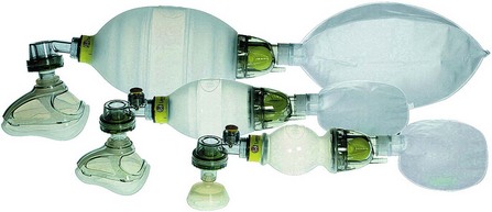
The self-inflating bag
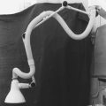
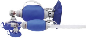
This bag may be made of silicone rubber or polyvinyl chloride (PVC), which is strengthened either by making its wall thicker, or by incorporating circular ‘ribs’ of identical material during manufacture (Fig. 8.1), so that in the resting state it is expanded. Another design (Ambu Mark IV, Fig. 8.2) has an outer covering of chloroprene or butyl rubber and a thick foam inner layer, which makes the bag expand in the resting state. All devices produced now are latex-free. The PVC versions are designed to be for single use only and the others are made to be steam autoclaved.
The respirable gas inlet mechanism is housed at one end and the non-rebreathing valve at the other.
The respirable gas inlet
This inlet has a number of components (Fig. 8.3):
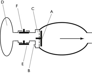
• A one-way flap valve (A). This is fitted to the inlet of the self-inflating bag. When the bag is squeezed, the gas pressure inside the bag rises and causes the flap valve to close. This prevents the escape of gas back through the inlet. When the bag is released, its self-inflating characteristic causes fresh gas from the respirable gas inlet to be indrawn. This may be air, oxygen or a mixture of both.
• A small bore nipple (B). This is mounted on the inlet, to allow admixture of oxygen.
• A wide bore inlet (C). This supplies the bulk of the gas entering the bag and is usually air, unless oxygen is added, as above. In the latter situation, the final concentration of oxygen delivered is a function of the amount of added oxygen and its dilution with air in the self-inflating bag.
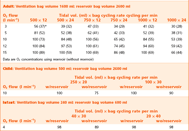
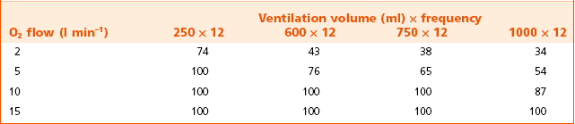
• A reservoir system (D). The inlet (C) may be fitted with a reservoir system. This feature is now widely used in almost all manual resuscitators. Its purpose is to store the oxygen fed into the system from the nipple (B). When the minute volume of oxygen supplied is greater than the volume given to the patient, the bag (D) will expand and will provide all the gas for ventilation (i.e. 100% oxygen). The reservoir must be fitted with an overflow valve (E) to prevent overfilling from too high a flow of oxygen and an entrainment valve (F) to allow ingress of air for when oxygen is not available or when lower concentrations of oxygen are required. Tables 8.1 and 8.2 show typical oxygen concentrations that are delivered under a variety of conditions, with two popular makes of resuscitators. The differences reflect the size of the relevant reservoirs used.
The non-rebreathing valve
Although primarily used in resuscitators, these valves may also be incorporated into anaesthetic breathing systems (see Chapter 27).
Ambu single shutter valve (Figs 8.4A, B and C)
This valve is the version used in all current Ambu products. Compared to previous models, it has been simplified and now incorporates a single, multi-function shutter only. The valve shown here is reusable and can be dismantled for cleaning and sterilizing. A disposable version is incorporated into the SPUR II (single patient use resuscitator) system (Fig. 8.5B). The part of the valve body containing the expiratory pathway in both types may be unscrewed and a spring loaded PEEP valve substituted.
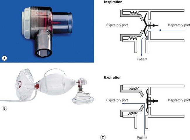
When this valve is used for controlled ventilation, manual compression of the self-inflating bag pushes gas against the concave aspect of the shutter causing it to move and occlude the expiratory port. The same movement opens the patient port to allow ingress of the gas.
The guide stem and flexible shutter are clearly visible through the transparent valve body and their ‘to and fro’ movement is an indicator of correct function.
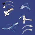
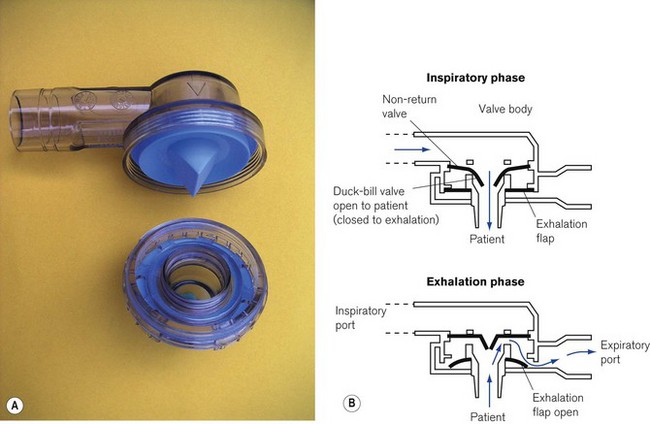
Laerdal pattern valve
This high-efficiency non-rebreathing valve (Fig. 8.5) is made in three sizes (adult, child, infant). The valve itself has three components, a duck-billed inspiratory/expiratory valve, a valve body housing inspiratory and expiratory ports and a non-return flap valve sited in the expiratory port. Originally designed by Laerdal, it is now used by many manufacturers for their resuscitators. It may be made for single use only, in which case the valve housing is sealed and cannot be opened. The reusable version made of autoclavable materials may be dismantled for cleaning and sterilizing. However, care must be taken to reassemble all the components correctly as there have been reports of misassembly:
• Inspiratory phase. The central duck-billed portion of the main valve opens when the attached self-inflating bag is squeezed, or when a patient inhales through it. Almost simultaneously the outer disc-shaped portion of the valve is pushed against the apertures in the valve body, thus sealing the expiratory pathway.
• Expiratory phase. Positive expiratory pressure from the elastic recoil of the patient’s lungs causes the duckbilled section of the valve to close, thus preventing rebreathing it into the bag. Escaping gas also lifts the flaps on a non-return valve in the expiratory port. This is a supplementary valve that prevents air from being aspirated into the expiratory port during spontaneous respiration.
• Other features. All the sizes have a 23 mm external diameter expiratory port and a 22 mm external diameter/15 mm internal diameter inspiratory port so as to minimize the possibility of misconnection. The child and infant models have overpressure safety valves built into the inspiratory port of the valve and which are set to blow off at a pressure of 45 cm H2O. If these pressures ever need to be exceeded, the safety valve can be overridden by finger pressure or a lock clip over the valve.
The self-inflating bag supplied with Laerdal resuscitators has thickened ribs of silicone rubber that provide the rigidity for the self-inflating action. These bags can be supplied with a supplementary reservoir bag (larger than that for the Ambu) for the supply of high oxygen concentrations to patients (Table 8.1). The entrainment port of the reservoir bags is fitted with a housing containing two valves. One is for air entrainment when little or no additional oxygen is used. The other is for the relief of any high-pressure build-up in the system from an excess of oxygen flow (see above).
Other uses for manual resuscitators
Most of the devices described above can be used with draw-over anaesthetic equipment to provide controlled ventilation when required. An example of such a system is described more fully in Chapter 27.
Barnes TA, McGarry WP, III. Evaluation of ten disposable manual resuscitators. Respir Care. 1990;35:960–968.
Baskett P, Zorab J. The resuscitation greats. Henning Ruben MD, FFARCS(I), FFARCS. The Ruben valve and the AMBU bag. Resuscitation. 2003;56:123–127.
Corley M, Ledwidge MK, Glass C, Grap MJ. The myth of 100% oxygen delivery through manual resuscitation bags. J Emerg Nurs. 1993;19:45–49.
Hermansen MC, Prior MM. Oxygen concentrations from self-inflating resuscitation bags. Am J Perinatol. 1993;10:79–80.
Hess D, Simmons M. An evaluation of the resistance to flow through the patient valves of twelve adult manual resuscitators. Respir Care. 1992;37:432–438.
Hess D, Spahr C. An evaluation of volumes delivered by selected adult disposable resuscitators: the effects of hand size, number of hands used, and use of disposable medical gloves. Respir Care. 1990;35:800–805.
Ho AM, Shragge BW, Tittley JG, Fedoryshyn JN, Puksa S. Exhalation obstruction due to Laerdal valve misassembly. Crit Care Med. 1996;24:362–364.
Kathy L, Johnston RRT, Khalid Aziz MA. The self-inflating resuscitation bag delivers high oxygen concentrations when used without a reservoir: implications for neonatal resuscitation. Respir Care. 2009;54:1665–1670.
Quintana S, Martinez Perez J, Alvarez M, Vila JS, Jara F, Nava JM. Maximum FIO2 in minimum time depending on the kind of resuscitation bag and oxygen flow. Intensive Care Med. 2004;30:155–158.
Smith G. Problems with mis-assembly of adult manual resuscitators. Resuscitation. 2002;53:109–111.
Smith G. Problems with mis-assembly of adult manual resuscitators. Resuscitation. 2002;55:347–348.