CHAPTER 91 Magnetic Resonance and Computed Tomographic Angiography of the Extracranial Carotid Arteries
There is clear evidence from multiple carotid trials, including a recent pooled data analysis, that surgical intervention with carotid endarterectomy (CEA) has significant benefits compared with medical therapy in symptomatic patients with severe carotid stenosis.1–3 Conventional catheter-based invasive angiography with cut film or intra-arterial digital subtraction angiography (DSA) has been the gold standard for measuring the carotid stenosis in these trials. The improved efficacy of noninvasive imaging techniques and the attendant risk of stroke during DSA has led many practices to adopt noninvasive modalities, such as Doppler ultrasound, magnetic resonance angiography (MRA), and/or computed tomography angiography (CTA) to replace this invasive study.
To understand how and when to apply these noninvasive modalities, we need to be able to balance our knowledge of the sensitivity and specificity of ultrasound, CTA, and MRA to identify a severe stenosis with the attendant risks of DSA as well as the risk of CEA. We can borrow a technique called decision analysis to help understand these various factors. Decision analysis takes the sensitivity and specificity of a noninvasive study, risk of stroke with DSA, risk of thromboembolic disease after CEA, risk of withholding CEA in patients with severe symptomatic stenosis, and risk of undergoing CEA with only moderate symptomatic carotid stenosis, as well as the costs of the noninvasive studies DSA, and CEA, into account.4 The results of this decision analysis allow us to test the risks or costs of various noninvasive carotid stenosis imaging strategies. Decision analysis demonstrates these various tradeoffs, which may not otherwise be apparent. Using DSA alone, all patients face the risk of procedural stroke. With MRA strategy, a few patients with false-positive results face an increased risk associated with CEA and a few patients with false-negative results face an increased risk because of the missed benefits of surgery. As Kuntz and colleagues4 have illustrated with decision analysis, it is better to have a false-positive result (and perform a CEA in patients with moderate stenosis, with its added slight morbidity per patient) than to have a false-negative result (and allow patients with severe stenosis not to undergo CEA, with a much higher morbidity per patient). Put another way, it is better to send a few extra patients for CEA who may not meet DSA requirements of severe stenosis than to miss patients with severe stenosis and withhold the important benefits of surgery.
Thus, choosing among the noninvasive tests, the option that yields the highest accuracy may not necessarily be better. One must consider the local sensitivity and specificity of a particular noninvasive imaging modality to detect a severe stenosis compared with DSA as well as the angiographic stroke risk and CEA stroke risk when deciding whether the locally acquired ultrasound, CTA, or MRA study can replace DSA in the preoperative evaluation of carotid stenosis (Fig. 91-1). Even when assuming a low angiographic stroke risk of 0.4%, as seen in the Veterans Affairs Cooperative Study, decision analysis has demonstrated that a noninvasive test with a sensitivity of 93% and specificity of 85% resulted in less morbidity than the DSA imaging strategy. This same analysis allows imagers and referring clinicians to compare the relative value of ultrasound, CTA, and MRA to replace DSA using site-specific data instead of relying on published results from outside facilities.
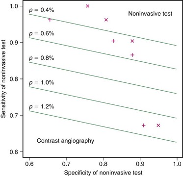
 FIGURE 91-1
MAGNETIC RESONANCE ANGIOGRAPHY
Techniques
Indications
Despite the availability of high-quality ultrasound, CTA, and MRA, no consensus exists regarding the optimal noninvasive imaging strategy for preoperative evaluation of carotid stenosis. This is particularly true for individual MRA techniques as well. In the 1990s, time-of-flight (TOF) MRA was reported to have good sensitivity and specificity in detecting internal carotid artery stenosis greater than 70% using North American Symptomatic Carotid Endarterectomy Trial (NASCET) criteria identified on DSA.5–7 However, carotid MRA became more clinically viable with the introduction of CE MRA, which offered the opportunity to cover more of the carotid artery distribution in a fraction of the scan time requirements of TOF MRA. With the advent of elliptical-centric phase reordering and effective timing of the gadolinium contrast bolus, first-pass CE MRA moved from research into routine clinical practice.
Some authors still insist that despite the ability to perform reliable CE MRA, TOF MRA remains the most accurate technique.8 For those who prefer CE MRA, three competing techniques have evolved. One approach uses multiple time points during the gadolinium bolus arrival with multiple, rapid, three-dimensional acquisitions with relatively low spatial resolution. To achieve a higher spatial resolution and improved temporal resolution, three-dimensional acquisitions reconstructed with a novel oversampling of the center of k-space are possible. This technique is termed time-resolved imaging of contrast kinetics (TRICKS).
Contrast-Enhanced Magnetic Resonance Angiography
As experience with gadolinium bolus arrival timing improved, many authors abandoned the time-resolved approach to carotid CE MRA in favor of a higher spatial resolution three-dimensional MRA technique at a single time point (Fig. 91-2). Carotid CE MRA benefits from a large residual carotid retention of the initial bolus of contrast injection and relative lack of motion concerns, which enables the acquisition of longer duration, high spatial resolution three-dimensional MRA. A difficultly with carotid CE MRA, however, has been the relatively brief arteriovenous enhancement window. Jugular venous enhancement can be seen as quickly as 5 seconds following carotid artery enhancement secondary to the lack of Gd-chelate contrast agent penetration of an intact blood-brain barrier and the rapid return of gadolinium contrast through the brain parenchyma to the jugular veins. By modeling the elliptical-centric k-space phase-ordering scheme, which provides a very efficient and compact central k-space sampling, Fain and associates9 have demonstrated that there is sufficient image contrast for preferential arterial high spatial resolution with the longer acquisition times necessary for high spatial resolution carotid CE MRA. The use of elliptical-centric three-dimensional MRA, in combination with an accurate bolus arrival scan or fluoroscopic triggering, allows for high spatial resolution carotid CE MRA with a voxel size of 1 mm3 or smaller, with reliable and high intra-arterial contrast and very little venous contamination.10 Use of a neurovascular coil ensures proper coverage of the carotid arteries from the aortic arch through the circle of Willis.
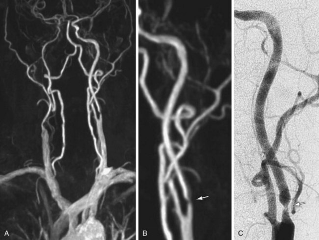
 FIGURE 91-2
(Courtesy of Dr. Winfried. A. Willinek, Department of Radiology, University of Bonn, Bonn, Germany.)
Spatial Resolution
Hinatiuk and coworkers11 have reviewed the effect of increased spatial resolution in depicting carotid stenosis as seen on CE MRA at 1.5T. In their patients with carotid artery stenosis, decreasing the voxel volume from 0.9 to 0.53 mm3 by increasing the scan matrix while keeping the FOV constant caused the scan time to increase from 21 to 40 seconds. The resulting CE MRA with improved resolution from the 0.53 mm3 resulted in the sharpest depiction of the carotid stenosis. With modern gradient systems, TRs for elliptical-centric acquisitions are roughly half what they were during the early work on carotid CE MRA. The authors made use of the 50% reduction in TR to almost double the spatial resolution of elliptical-centric carotid CE MRA compared with the initial 0.8 to 1.0 mm3 voxel size while maintaining an imaging time of 40 seconds. This reduction in voxel volume to 0.53 mm3 resulted in a much better depiction of the carotid stenosis. A total of 30 mL of Gd-chelate contrast medium was used to achieve adequate signal-to-noise ratio (SNR). Further decreases in voxel volume, by extending the acquisition time to 50 to 60 seconds, did not improve the vessel depiction because of both a drop in SNR and sharpness losses, possibly from motion. Nael and colleagues12 have extended the resolution of elliptical-centric carotid CE MRA to 0.44 mm3 by making use of the extra SNR at 3.0T.
Parallel Imaging
Parallel imaging is another technique to shorten the acquisition time of first-pass elliptical-centric carotid CE MRA and/or support higher spatial resolution. In general, the efficacious use of parallel imaging allows one to maintain the recommended 1.0 mm or less in plane spatial resolution with a voxel volume of 0.8 mm3 or less while maintaining adequate SNR to achieve a good-image quality. Most authors have recommended using a twofold (i.e., 2×) acceleration factor at 1.5 T. The imaging volume is then increased by 50% in the z direction of the coronal CE MRA acquisition (anteroposterior direction). This simplifies the prescription of the imaging volume. The resulting CE MRA sequence is 25% faster compared with a smaller nonaccelerated prescription. By traversing the center of k-space faster with parallel imaging, the SNR benefits from the gadolinium bolus can be maximized. This helps offset the loss of SNR from the parallel imaging technique. Fourfold acceleration of 3.0-T carotid CE MRA using parallel imaging in phase- and detector row–encoding directions is also possible. Almost isotropic 0.7- × 0.7- × 0.9-mm resolution (0.44 mm3 voxel volume) CE MRA from the aortic arch through the circle of Willis have been reported with this 3.0-T MR technique.12 This study demonstrated some of the highest spatial resolution carotid CE MRA examinations ever achieved with a large FOV (Fig. 91-3).
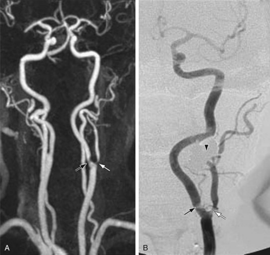
 FIGURE 91-3
Dedicated Carotid Coils
A dedicated neurovascular phased array coil is used in most cases because it not only provides an optimized SNR for carotid imaging and the ability to implement parallel imaging techniques, but also extends carotid artery coverage from its origin at the aortic arch through the circle of Willis. More recently, dedicated carotid surface coils that cover 14 to 18 cm of the midneck have become commercially available at 3.0 T. These dedicated surface coils provide another factor of improvement in SNR compared with the larger FOV clamshell design neurovascular coils that extend from the aortic arch through the circle of Willis. These dedicated carotid surface coils support even higher spatial resolution carotid CE MRA with a voxel size of 0.59 × 0.59 × 0.80 mm without zero filling. This corresponds to a voxel volume of 0.27 mm3 with dedicated carotid surface coils at 3.0 T compared with 0.44 mm3 as used by Nael and associates12 at 3.0 T using a large FOV clamshell neurovascular coil and 0.53 to 0.66 mm3 as used by Hnatiuk and coworkers11 and Willinek and colleagues13 at 1.5 T with a large FOV clamshell neurovascular coil. Carotid CE MRA at 3.0 T using dedicated surface coils results in the highest resolution study achieved to date with CE MRA, and competes favorably with the spatial resolution of the 64-detector CTA.
Field of View
Raw resolution alone may not fully explain the ability to dedicate the carotid lumen stenosis on the CE MRA. According to the study by Fain and associates,9 one key factor in improving the performance of elliptical-centric phase-reordered CE MRA as measured by the point spread function (PSF) is to minimize the phase FOV in both the y– and z-axes. By focusing on just the middle 14 to 18 cm of the neck, we can limit the phase FOV in both directions while generating substantially higher spatial resolution CE MRA compared with using a larger FOV and an eight-channel neurovascular coil. At 3.0 T, there is a sufficient carotid SNR to realize improved spatial resolution benefits using a small FOV and dedicated carotid surface coils. The improved PSF provided by the smaller phase FOV should result in a sharper depiction of the arterial lumen boundary compared with a similarly prescribed spatial resolution using a larger FOV. Stated another way, the same spatial resolution prescribed using a large FOV would result in inferior CE MRA compared with a small FOV because of the effect of the smaller phase FOV on the PSF. The arterial lumen boundaries would not be as sharp, despite the same prescribed resolution. This discussion assumes that we somehow generate enough SNR using the larger neurovascular coil, too. In addition to small FOV in the xy direction, we can acquire less coverage in the z direction by covering only the middle portion of the neck. Larger phase FOV in the z direction is required to cover the entire course of the carotid artery from the arch through the circle of Willis. If we desire the highest resolution carotid CE MRA, Fain9 would predict that a small phase FOV of approximately 18 cm in both the y and z direction would be optimal.
Initial results of dedicated carotid coil limited FOV carotid CE MRA have confirmed excellent correlation with DSA (Fig. 91-4).14 In patients for whom coverage of the carotid arteries that is limited to a 15 to 18 cm FOV in the neck is sufficient, dedicated carotid coil 3.0-T CE MRA represents the highest resolution noninvasive study possible today. This method is particularly well suited for clinical practices in which the decision to proceed to CEA is based on ultrasound without the need of the noninvasive testing to visualize the remainder of the carotid artery directly. If there is a carotid CTA that is limited because of extensive calcifications, the dedicated carotid coil 3.0-T CE MRA can depict the carotid stenosis without artifacts from the calcifications with similar or higher spatial resolution than CTA (Fig. 91-5). The use of such high SNR dedicated carotid surface coils at 3.0 T also makes carotid plaque imaging possible. Although this is still experimental, there is great potential to depict not only carotid stenosis but the underlying plaque causing the narrowing (Fig. 91-6). There is a strong possibility that carotid plaque characteristics as depicted by MRI may be a predictor of which patients with moderate asymptomatic carotid stenosis are at risk to proceed on to stroke or a transient ischemic attack (TIA).15
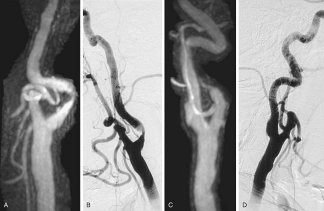
 FIGURE 91-4
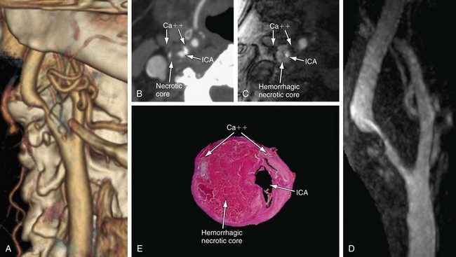
 FIGURE 91-5
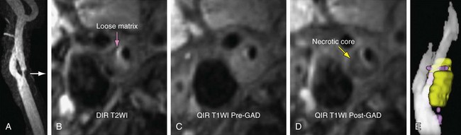
 FIGURE 91-6
Summary of Using Carotid Contrast-Enhanced Magnetic Resonance Angiography to Depict Carotid Stenosis
Summary of Recommended MRA Techniques
Based on published data, it is reasonable to conclude that CE MRA studies using 1.0 mm or less in-plane spatial resolution combined with 0.8- to 1.2-mm-thick partition thickness (≤0.8 mm3 voxel size) can result in accurate MRA examinations that compare favorably with DSA. The specific protocols will vary depending on the available MR field strength, available RF coils and channels, availability of parallel imaging techniques, and available gradient strength and minimum TR for elliptical-centric carotid CE MRA. This is in keeping with the initial simulations of first-pass elliptical-centric phase-reordered CE MRA that predicted the best performance with high resolution while maintaining a minimum-phase FOV in the y and z directions.9
A three-way prospective study of a submillimeter spatial resolution first-pass CE MRA, with a time-resolved CE MRA and a noncontrast TOF MRA, in comparison with the gold standard of rotational DSA for the preoperative evaluation of carotid stenosis, would determine which technique is superior if the study included a sufficiently large number of patients. In the absence of such a study, the aforementioned analysis suggests that 1 mm or less in-plane spatial resolution first-pass CE MRA, with a voxel size of 0.8 mm3 or less, perhaps combined with three-dimensional TOF MRA, is the best technique to depict carotid stenosis at the carotid bifurcation. Select recommended protocols are listed in Table 91-1.
TABLE 91-1 Sample Imaging Parameters for Contrast-Enhanced MRA of the Extracranial Carotid Arteries: Various MR Scanner Platforms
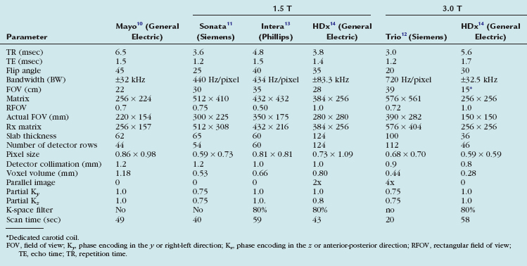
The original elliptical-centric carotid CE MRA protocol, as recommended by its developers at the Mayo Clinic in the late 1990s, is listed in the first column of Table 91-1. This carotid CE MRA technique has been shown to provide excellent sensitivity and specificity to detect more than 70% diameter stenosis as compared with DSA. It is critical to note that these high levels of sensitivity and specificity occurred only when maintaining submillimeter in-plane resolution and when measuring stenosis on multiplanar reformation (MPR) and not maximum intensity projections.
With recent improvements in gradient hardware and parallel imaging, further improvements on the original resolution of elliptical-centric carotid CE MRA are possible at 1.5 T. The middle three columns of Table 91-1 illustrate examples from three of the major MRA manufacturers. All imaging parameters listed in Table 91-1 are optimized for high spatial resolution carotid CE MRA using roughly a double dose of a traditional extracellular GBCAs (e.g., 0.2 mmol/kg or roughly 30 mL in most adult patients).
The last two columns highlight the potential for the future. The group at UCLA has combined 3.0 T MR with a dedicated 12-element neurovascular clamshell-style coil and parallel imaging in two directions to achieve higher resolution elliptical-centric carotid CE MRA compared with the results at 1.5 T. (0.44 versus 0.65 mm3).12 We have been using research carotid coils (see Table 91-1, far left column) that can image a 15- to 18-cm FOV and cover from the carotid bifurcation to the skull base; combined with 3.0 T MR imaging, this can achieve very high spatial resolution carotid CE MRA (0.28 mm3 resolution). Most of the major MR manufacturers now or will soon offer similar dedicated clinical carotid surface coils. The first generation of these FDA-approved clinical carotid coils covers the midneck region and are capable of imaging from the carotid bifurcation to near the skull base. Second-generation coils should be able to combine coverage of the midneck with brain imaging at 3.0 T to offer unprecedented resolution with carotid MRA.
Pitfalls and Solutions
Adequate Signal- and Contrast-to-Noise Ratios
In general, properly performed CE MRA will provide a high vascular SNR and CNR. Pushing spatial resolution to the recommended 1.0 mm or less in-plane resolution with a voxel size of 0.8 mm3 or less requires much attention to technique, equipment selection, and timing of imaging with the transit of the contrast media bolus arrival. All the major MRA manufactures now offer eight-channel or higher neurovascular coils for 1.5- and 3.0-T MRA systems. In addition, many authors now use a 0.2-mmol/kg dose of GBCA or weight-independent dosing of 20 to 30 mL. This is usually injected at 2 to 3 mL/sec followed by a saline flush at a similar rate. This provides a sufficient arterial SNR/CNR to support the recommended higher spatial resolution required for proper first-pass carotid CE MRA in most patients imaged at 1.5 T. It may be possible to use only a single dose of GBCA in combination with 3.0 T to achieve 0.5 mm3 or lower resolution and still maintain a good SNR/CNR.16
Adequate Spatial Resolution While Minimizing Imaging Time and Motion Artifact
It is clear from the work of Hoogeveen and colleagues17 that at least three pixels are needed across a vessel to define the degree of stenosis. This would suggest that using in-plane resolution on the order of 0.5 to 0.7 mm would improve depiction of relevant stenotic carotid arteries with diameters in the range of 1.5 to 2.5 mm. This assumes that there is a sufficiently high arterial SNR and the examination is not so long as to result in patient motion artifacts.
Image Interpretation
Postprocessing
Use of Direct Caliper Measurements
Subjective visual inspection alone is not recommended for the evaluation of carotid artery stenosis on carotid CE MRA. Subjective inspection may be acceptable as an initial screening tool to exclude the presence of a 70% to 99% stenosis, but caliper measurements are warranted to confirm the presence of such stenosis.18 As shown Figure 91-7, the maximum intensity projection (MIP) image can strongly suggest a severe stenosis. MPR oblique axial images through the level of maximum stenosis clearly demonstrate only a moderate stenosis, as was confirmed on subsequent DSA. All MRA manufacturers and picture archival and communication system (PACS) vendors now offer simple postprocessing tools to generate MPR in any arbitrary oblique plane. This greatly simplifies the work flow and makes it possible to include a review of MPR images of suspected regions of carotid stenosis in the routine clinical setting.
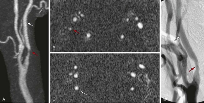
 FIGURE 91-7
Use of Multiplanar Reformations in Caliper Measurements of Carotid Stenosis
The MIP algorithm results in decreased noise by decreasing the projected variance of the background compared with that in the source axial images. This leads to increased CNR in the MIP images. However, in the case of a projection through an area with minimal flow-related enhancement, as occurs in regions of carotid stenosis, the MIP algorithm can decrease the CNR so that the vessel is less apparent in the final MIP image. MPR images display the original source axial images in an arbitrary oblique plane. The weighted sum average used to reformat the data leads to an improvement in CNR because of the averaging effect. This improvement in CNR is not dependent on background suppression and vessel contrast is maintained, even in regions of carotid stenosis.19 MPR of three-dimensional TOF MRA was shown to be highly correlated with DSA for two observers. No statistically significant difference between three-dimensional TOF MPR and DSA was seen. By contrast, the same three-dimensional TOF MRA sequence now analyzed by measurements of carotid stenosis on MIP images did show a significant difference compared with DSA (Fig. 91-8). The MIP images overestimated stenosis by approximately 10%. Lell and associates20 have also demonstrated the highest concordance of carotid stenosis measurements on carotid MRA using MPR images. Thus, caliper measurements of carotid stenosis as seen on MRA are best performed using MPR and not MIP images.
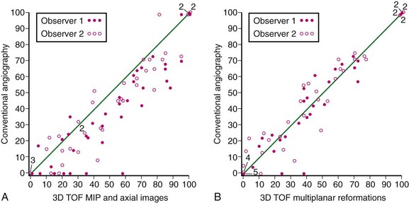
 FIGURE 91-8
Reporting
Criteria for Measuring and Reporting Internal Carotid Artery Stenosis
There are three different methods for quantifying diameter stenosis on CE MRA when using DSA as the gold standard. These include the NASCET, European Carotid Surgery Trial (ECST), and common carotid (CC) methods. NASCET reports the ratio of the stenotic internal carotid artery (ICA) compared with the distal nontapering ICA. ECST uses the estimated diameter of the carotid bulb in the denominator. The CC method uses the distal CC artery (CCA) free of obvious disease as the denominator. When U-King-Im and colleagues21 evaluated 284 carotid arteries on both CE MRA and DSA, all three methods were adequate for evaluation of DSA. With CE MRA, however, this study supported the use of the NASCET method because of improved sensitivity for the detection of severe stenosis.
CAROTID COMPUTED TOMOGRAPHIC ANGIOGRAPHY
Technical Requirements
Detailed protocols including collimation, table speed, and gantry speed are different among scanners provided by multiple vendors. Advances in multidetector CT (MDCT) technology have permitted higher quality CTA with thinner collimation (up to 0.5 mm) and faster gantry speed (up to 0.33 sec/rotation).22
Techniques
Indications
Advances in CT scanner technology have resulted in the development of CTA that allows less invasive vascular imaging technique to be used widely in clinical environment. Although earlier studies to evaluate extracranial carotid artery stenosis using single-detector helical CT have shown a certain level of concordance with DSA as the gold standard,23 single-detector helical CT had tradeoffs of limited scan volume and z-axis resolution. Newer generation MDCT and subsecond rotation capabilities have led to quantum leaps that provide excellent coverage from the aorta arch through the circle of Willis, with z-axis resolutions of 0.5 to 0.625 mm. Using these volume data sets with isotropic submillimeter voxel dimensions, CTA images in every plane of reformation can be generated without losing resolution (Fig. 91-9). Faster gantry rotation speed and increased table speed support higher temporal resolution. Improved spatial and temporal resolution, as well as the development of postprocessing techniques, has allowed multidetector CTA to become a clinically and relevant less invasive technique to evaluate carotid artery disease and has the potential to replace DSA for the evaluation of carotid artery stenosis.
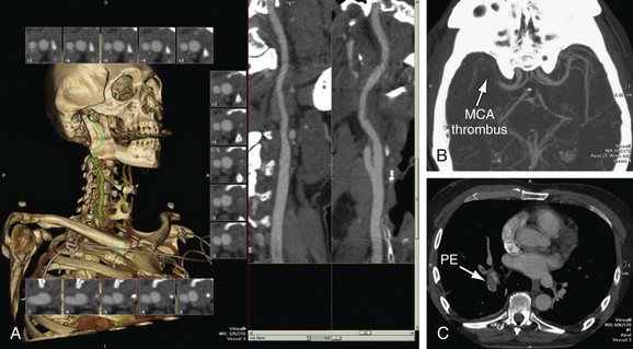
 FIGURE 91-9
The most common indication for a carotid CTA is evaluation of suspected atherosclerotic ICA stenosis based on a screening duplex ultrasound study. Neurologists and neurosurgeons tend to prefer MRI or MRA evaluation of carotid stenosis, especially if detailed imaging of the brain is required clinically. Vascular surgeons and interventionalists tend to prefer CTA, especially with the familiar depiction of adjacent soft tissues from CT studies (Fig. 91-10). Routine diagnostic invasive DSA to assess carotid stenosis has essentially been replaced by noninvasive methods. As with MRA, there have been significant improvements in CTA technology. Although we will summarize the current peer-reviewed literature, it is important to remember that reported CTA accuracy from single center studies may be difficult to duplicate in clinical practice. As with MRA, we recommend direct comparison of the accuracy of CTA with DSA locally. Local expertise may be a deciding factor in choosing which noninvasive study to use to evaluate suspected carotid stenosis.
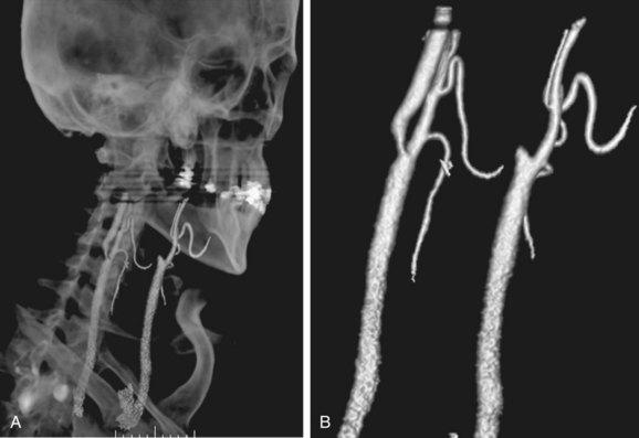
 FIGURE 91-10
In a meta-analysis of 864 patients in 28 studies using a single-detector row CTA technique, Koelemay and coworkers23 have reported a pooled sensitivity and specificity for detection of a 70% to 99% stenosis that were 85% (95% confidence index [CI], 79 to 89) and 93% (95% CI, 89 to 96). For detection of an occlusion, the sensitivity and specificity were 97% (95% CI, 93 to 99) and 99% (95% CI, 98 to 100). They concluded that CTA is an accurate modality for the detection of severe carotid stenosis, especially for detection of occlusions. Most early experience with single- or four-detector CTA demonstrated a tendency to underestimate carotid stenosis compared with DSA. This leads to high specificity but lower sensitivity with CTA estimation of carotid stenosis. As noted, decision analysis tells us that we need a noninvasive study with high sensitivity to optimize noninvasive imaging strategies and minimize costs and/or morbidity.
Even when limited to four- and eight-detector CTA, limiting collimation to 1 mm may improve correlation of CTA with DSA. Berg and colleagues24 have reported a 91% accuracy of four-detector CTA with 1-mm collimation compared with rotational DSA, although there was still a tendency to underestimate stenosis on CTA. Bucek and associates25 have reported 97% sensitivity and 66% specificity in the detection of severe carotid stenosis using four-detector CTA with 1-mm collimation when reviewed by an experienced interpreting physician and using dedicated postprocessing techniques to allow visualization of oblique axial images through the level of maximum stenosis. The accuracy was decreased with a second, less experienced observer. The administration of high-concentration contrast medium and/or the availability of 64-detector CT scanners are expected to reverse the lower sensitivity of single- or four-detector CTA compared with DSA.26 Again, the role of CTA versus MRA in the evaluation of carotid stenosis identified on screening duplex ultrasound will depend heavily on the local interpreting physician’s expertise with each noninvasive technique as well as the referral patterns and preferences of the requesting physicians.
Studies have reported 100% sensitivity and specificity in differentiating complete ICA occlusion from near-occlusion.25,27 In the largest of these, Chen and coworkers27 evaluated 57 ICAs with total and near-occlusions with DSA and four-detector CTA. CTA correctly depicted all total and near-occlusions. In total occlusions, the length of the stump and retrograde flow were all accurately described by CTA. In near-occlusions, the sites of tight stenoses were also correctly identified by CTA. It was concluded that CTA may be considered a substitute for DSA in confirming the ultrasound results in diagnosing total versus near-occlusion of an ICA.
The use of stents to treat carotid stenosis has been increasing. CTA, especially with 64-detector CT scanners, can evaluate the status and patency of the carotid artery previously treated with stenting. The success rate in depicting the carotid lumen in the presence of a stent is higher than for the evaluation of coronary stents, given both the larger size of the carotid artery and the decrease in motion artifact compared with coronary CTA (Fig. 91-11).
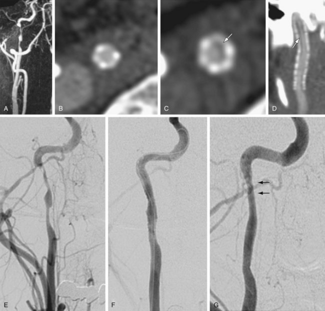
 FIGURE 91-11
Carotid artery dissection is a possible cause of stroke, especially in young patients and patients reporting pain, headache, Horner’s syndrome, or neck trauma. Carotid artery dissections typically occur in the distal cervical portion of the ICA and extend into the skull base. CTA may demonstrate long irregular ICA stenosis or tapered occlusion. There may be an intimal flap. Care needs to be taken to evaluate the ICA, especially at the skull base of axial images if there is a clinical concern of carotid dissection. In patients with head and neck trauma, CTA is the fastest and most comprehensive method for evaluating for vascular injury, soft tissue abnormality, and fracture (Fig. 91-12).
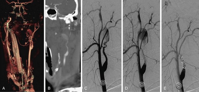
 FIGURE 91-12
Contraindications
Renal Failure
The development of contrast medium–induced nephropathy (CIN) is low in people with normal renal function, varying from 0% to 5%.2 Preexisting renal impairment increases the frequency of this complication, ranging from 12% to 27%. Consideration of alternative imaging techniques that do not require administration of a nephrotoxic contrast agent is important. If CTA is necessary clinically in patients with renal impairment, there are several options for pretreatment prior to the CTA to minimize the risk of CIN. Those include volume expansion, use of low- or iso-osmolar contrast media, and stopping nephrotoxic drugs such as nonsteroidal anti-inflammatory drugs.28 Volume expansion can be achieved with the intravenous injection of 100 mL/hr of 0.9% saline starting 4 hours prior to contrast medium administration and continuing for 24 hours if a patient does not have congestive heart failure. If there is no contraindication to oral administration, free fluid intake should be encouraged. Also, 64-detector CTA has a potential advantage of decreasing the likelihood of CIN by reducing the amount of iodinated contrast material required for good-quality CTA because of the faster scan time. A saline bolus chase is also effective to reduce iodinated contrast material without significantly reducing contrast enhancement in the arterial phase.29
Technique Description
CT parameters to obtain optimal image quality on carotid CTA depends on the type of MDCT scanner that is available. In general, the use of the thinnest possible slice thickness is recommended. Although vendor-specific, a detector row thickness of 1 mm is possible with four- or eight-detector CT scanners and slice thicknesses of 0.5 to 0.6 mm are possible with 16- and 64-detector CT scanners. Rotation speed also varies from 0.3 to 0.7 sec/rotation, depending on the number of detectors and the vendor. Some vendors also allow variable gantry speeds during the acquisition. In these cases, faster acquisition in the neck, where the vessels are larger, and slower acquisition in the head, where the circle of Willis arteries are smaller, is possible. There have also been significant improvements in CT tube design and heat dissipation. In an average-sized patient, with a tube voltage of 120 kVP, milliamperage in the range of 200 to 240 mAs is required for carotid CTA. Modern 16- and 64-detector CT scanners also provide automatic mAs adjustments, with higher mAs through the shoulders to decrease streak artifact. A mAs range of 200 to 800 at 0.4 second with a noise index of 10 provides a good balance of quality and radiation exposure.30
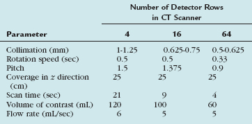
Attention to the type, volume, and site of intravenous injection of iodinated contrast material will affect the final carotid CTA image quality. A large-bore intravenous catheter of at least 20 gauge in the right antecubital fossa is best. Arterial enhancement is provided by the intravenous injection of 80 to 120 mL of nonionic iodinated contrast material at a variable rate, from 3 to 6 mL/sec. The volume and rate of injection vary widely, depending on the number of detectors available (Table 91-2). Recently, high-concentration contrast material of 370 to 400 mg I/mL has been shown to provide earlier and higher peak enhancement with lower injection rates of approximately 4 mL/sec. The use of a saline flush after injection of the iodinated contrast can maintain good CTA image quality while minimizing the total dose of contrast injected. The saline flush also minimizes the artifact of highly concentrated contrast in the subclavian vein, which can cause streak artifacts near the aortic arch and takeoff of the great vessels. Schuknecht and colleagues26 have recently reported their initial experience in 37 patients scanned with a modern 64-detector CT. In their study, a relatively small volume (25 mL) of high-concentration iodinated contrast agent—400 mg I/mL of iomeprol 400 (Bracco Diagnostics)—was injected by a power injector at a flow rate of 4 mL/sec, followed by a 40-mL flush of saline at the same injection rate, which resulted in good-quality carotid CTA in all cases. An automated contrast bolus detection and triggering algorithm provided by the manufacturer were used to time the beginning of the carotid CTA. In older MDCT scanners, in which a short, compact contrast bolus with a saline flush to minimize streak artifact in the subclavian vein was not possible, de Monye and associates31 demonstrated that the use of a craniocaudal scan direction results in slightly lower attenuation of the carotid arteries and much lower attenuation of the subclavian veins and superior vena cava, with a resulting decrease in streak artifacts near the aortic arch and great vessel takeoff.
Pitfalls and Solutions
Densely calcified plaque, especially at the carotid bifurcation, can lead to an overestimation of the stenosis on CTA because of the blooming artifact. The window level settings are critical to the accurate interpretation of carotid stenosis. The optimal evaluation of carotid stenosis may be from multiplanar reformatted images perpendicular to the longitudinal axis of the ICA at the level of maximum stenosis and the distal nontapering portion of the ICA (oblique axial MPR). Images should be displayed with a window level setting of 700/200 HU unless there are dense calcifications, in which case wider settings (1100/200 HU) are recommended.20 Calcifications may obscure the true residual carotid lumen on MIPs and volume rendered (VR) images. They are useful for global screening of the large data set from carotid CTA, but accurate assessment of the carotid stenosis requires review of the source axial and oblique axial MPR images.
Artifact from overlapping bone, especially the sternum, can also obscure the aortic arch and the takeoff of the great vessels on MIP or VR images. Curved MPR, thin-section MIP, and bone subtraction algorithms can help in the depiction of stenosis involving the takeoff of the great vessels from the aortic arch. Although still in the development stage, bone subtraction algorithms with motion compensation can provide higher quality CTA than purely rigid registration methods.32 When there is little swallowing artifact, there is even the potential to remove plaque calcifications at the carotid bifurcation. Others have studied dual-energy CT to automate the segmentation of bone from contrast-enhanced carotid lumen. Initial experience with dual-source MDCT did improve coronary artery depiction from improved temporal resolution, but it is more difficult to segment and subtract bone and calcium from the enhanced arterial lumen. Research in this area is continuing and looks promising.
Image Interpretation
Postprocessing
Any desired two-dimensional section, which is longitudinal or cross sectional to the vessel axis, can be generated from a stack of CT data with MPR. Cross-sectional MPR images can visualize luminal shape accurately, even if it is eccentric or concentric, and results in good interobserver variability for grading of the degree of stenosis.4 It is recommended to use cross-sectional MPR images to measure the luminal dimension.5 Some current workstations can automatically generate consecutive cross-sectional MPR images perpendicular to the vascular axis, with occasional manual correction, which is not a time-consuming method (Fig. 91-13). The drawback of cross-sectional MPR images is that it is difficult to get an overview of the target arteries, which can be overcome by using other imaging technique, such as CPR, MIP, and VR methods. Attention should be paid not to miss multiple lesions at the target artery because tandem lesions are a common feature in atherosclerosis.
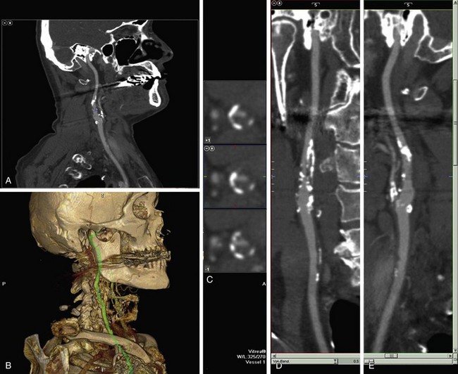
 FIGURE 91-13
Carotid Artery Ulceration
MDCT angiography is helpful for the detection of ulceration. Wintermark and coworkers33 have demonstrated that CTA performs well in detecting ulcerations (κ < 0.855) when compared with histologic examination. Saba and colleagues34 have demonstrated that MDCT angiography for the detection of carotid ulceration confirmed by surgical specimens reveals 93.9% sensitivity (95% CI, 0.858 to 1.021), and a 98.7% specificity (95% CI, 0.961 to 1.012). They described the usefulness of cross-sectional images and VR to detect ulceration.
Reporting
With the advent of cross-sectional imaging of carotid stenosis by CTA and MRA, direct measurement of both the carotid artery diameter and area stenosis are now possible (Fig. 91-14). Poiseuille’s law states that the amount of blood flow in a tubular structure is proportional to the cross-sectional area. This would imply that area stenosis and not diameter stenosis would correlate best with flow in the ICA. Bucek and associates have shown that measurements of the narrowest ICA stenosis on CTA in 178 vessels are a reasonable predictor of the cross-sectional area.25 This probably explains why the original diameter stenosis measurements from NASCET worked in the first place. When new multicenter trials evaluating CTA and/or MRA to guide medical versus surgical treatments are planned, it would be reasonable to look at direct area stenosis measurements instead of the original indirect NASCET diameter stenosis measurements. Until those studies are available, it is most helpful to report ICA stenosis based on the NASCET criteria. The actual linear measurement of minimal ICA diameter and distal ICA diameter should be reported. The status of the lumen as smooth, irregular, or ulcerated should also be reported. Any tandem stenoses elsewhere in the carotid artery, as well as the status of the circle of Willis, are important to describe. Finally, any significant adjacent soft tissue or bony abnormalities should be reported.
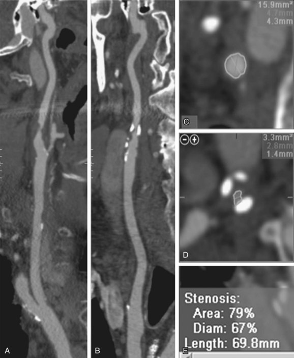
 FIGURE 91-14


Briley-Saebo KC, Mulder WJ, Mani V, et al. Magnetic resonance imaging of vulnerable atherosclerotic plaques: current imaging strategies and molecular imaging probes. J Magn Reson Imaging. 2007;26:460-479.
Enterline DS, Kapoor G. A practical approach to CT angiography of the neck and brain. Tech Vasc Interv Radiol. 2006;9:192-204.
Jewells V, Castillo M. MR angiography of the extracranial circulation. Magn Reson Imaging Clin North Am. 2003;11:585-597.
Kaufmann TJ, Kallmes DF. Utility of MRA and CTA in the evaluation of carotid occlusive disease. Semin Vasc Surg. 2005;18:75-82.
Koelemay MJ, Nederkoorn PJ, Reitsma JB, Majoie CB. Systematic review of computed tomographic angiography for assessment of carotid artery disease. Stroke. 2004;35:2306-2312.
Maldonado TS. What are current preprocedure imaging requirements for carotid artery stenting and carotid endarterectomy? Have magnetic resonance angiography and computed tomographic angiography made a difference? Semin Vasc Surg. 2007;20:205-215.
Nederkoorn PJ, van der Graaf Y, Hunink MG. Duplex ultrasound and magnetic resonance angiography compared with digital subtraction angiography in carotid artery stenosis: a systematic review. Stroke. 2003;34:1324-1332.
Saam T, Hatsukami TS, Takaya N, et al. The vulnerable, or high-risk, atherosclerotic plaque: Noninvasive MR imaging for characterization and assessment. Radiology. 2007;244:64-77.
Takhtani D. CT neuroangiography: a glance at the common pitfalls and their prevention. AJR. 2005;185:772-783.
Wardlaw JM, Chappell FM, Stevenson M, et al. Accurate, practical and cost-effective assessment of carotid stenosis in the UK. Health Technol Assess. 2006;10:1-182.
1 North American Symptomatic Carotid Endarterectomy Trial Collaborators. Beneficial effect of carotid endarterectomy in symptomatic patients with high-grade carotid stenosis. N Engl J Med. 1991;325:445-453.
2 Randomised trial of endarterectomy for recently symptomatic carotid stenosis: final results of the MRC European Carotid Surgery Trial (ECST). Lancet. 1998;351:1379-1387.
3 Rothwell PM, Eliasziw M, Gutnikov SA, et al. Analysis of pooled data from the randomised controlled trials of endarterectomy for symptomatic carotid stenosis. Lancet. 2003;361:107-116.
4 Kuntz KM, Skillman JJ, Whittemore AD, Kent KC. Carotid endarterterectomy in asymptomatic patients—is contrast angiography necessary? A morbidity analysis. J Vasc Surg. 1995;22:706-716.
5 Anderson CM, Lee RE, Levin DL, et al. Measurement of internal carotid artery stenosis from source MR angiograms. Radiology. 1994;193:219-226.
6 Kent KC, Kuntz KM, Patel MR, et al. Perioperative imaging strategies for carotid endarterectomy. An analysis of morbidity and cost-effectiveness in symptomatic patients. JAMA. 1995;274:888-893.
7 Patel MR, Kuntz KM, Klufas RA, et al. Preoperative assessment of the carotid bifurcation. Can magnetic resonance angiography and duplex ultrasonography replace contrast arteriography? Stroke. 1995;26:1753-1758.
8 Townsend TC, Saloner D, Pan XM, Rapp JH. Contrast material-enhanced MRA overestimates severity of carotid stenosis, compared with three-dimensional time-of-flight MRA. J Vasc Surg. 2003;38:36-40.
9 Fain SB, Riederer SJ, Bernstein MA, Huston J3rd. Theoretical limits of spatial resolution in elliptical-centric contrast-enhanced three-dimensional-MRA. Magn Reson Med. 1999;42:1106-1116.
10 Huston J3rd, Fain SB, Wald JT, et al. Carotid artery: elliptical centric contrast-enhanced MR angiography compared with conventional angiography. Radiology. 2001;218:138-143.
11 Hnatiuk B, Emery DJ, Wilman AH. Effects of doubling and tripling the spatial resolution in standard three-dimensional contrast-enhanced magnetic resonance angiography of carotid artery disease. J Magn Reson Imaging. 2008;27:71-77.
12 Nael K, Villablanca JP, Pope WB, et al. Supra-aortic arteries: contrast-enhanced MR angiography at 3.0 T—highly accelerated parallel acquisition for improved spatial resolution over an extended field of view. Radiology. 2007;242:600-609.
13 Willinek WA, von Falkenhausen M, Born M, et al. Noninvasive detection of steno-occlusive disease of the supra-aortic arteries with three-dimensional contrast-enhanced magnetic resonance angiography: a prospective, intra-individual comparative analysis with digital subtraction angiography. Stroke. 2005;36:38-43.
14 DeMarco JK, Huston J3rd, Nash AK. Extracranial carotid MR imaging at 3 T. Magn Reson Imaging Clin North Am. 2006;14:109-121.
15 Takaya N, Yuan C, Chu B, et al. Association between carotid plaque characteristics and subsequent ischemic cerebrovascular events: a prospective assessment with MRI—initial results. Stroke. 2006;37:818-823.
16 Tomasian A, Salamon N, Lohan DG, et al. A contrast dose reduction study for three-dimensional high spatial resolution contrast-enhanced magnetic resonance angiography of supraaortic arteries at 3.0 Tesla. Annual Meeting of the Society of Cardiovascular MR, Los Angeles, 2008, p 158.
17 Hoogeveen RM, Bakker CJ, Viergever MA. Limits to the accuracy of vessel diameter measurements in MR angiography. J Magn Reson Imaging. 1998;8:1228-1235.
18 U-King-Im J, Graves MJ, Cross JJ, et al. Internal carotid artery stenosis: accuracy of subjective visual impression for evaluation with digital subtraction angiography and contrast-enhanced MR angiography. Radiology. 2007;244:213-222.
19 De Marco JK, Nesbit GM, Wesbey GE, Richardson D. Prospective evaluation of extracranial carotid stenosis: MR angiography with maximum-intensity projections and multiplanar reformation compared with conventional angiography. AJR Am J Roentgenol. 1994;163:1205-1212.
20 Lell M, Fellner C, Baum U, et al. Evaluation of carotid artery stenosis with multisection CT and MR imaging: influence of imaging modality and postprocessing. AJNR Am J Neuroradiol. 2007;28:104-110.
21 U-King-Im JM, Trivedi RA, Cross JJ, et al. Measuring carotid stenosis on contrast-enhanced magnetic resonance angiography: diagnostic performance and reproducibility of 3 different methods. Stroke. 2004;35:2083-2088.
22 Saba L, Sanfilippo R, Pirisi R, et al. Multidetector-row CT angiography in the study of atherosclerotic carotid arteries. Neuroradiology. 2007;49:623-637.
23 Koelemay MJ, Nederkoorn PJ, Reitsma JB, Majoie CB. Systematic review of computed tomographic angiography for assessment of carotid artery disease. Stroke. 2004;35:2306-2312.
24 Berg M, Zhang Z, Ikonen A, et al. Multi-detector row CT angiography in the assessment of carotid artery disease in symptomatic patients: comparison with rotational angiography and digital subtraction angiography. AJNR Am J Neuroradiol. 2005;26:1022-1034.
25 Bucek RA, Puchner S, Haumer M, et al. CTA quantification of internal carotid artery stenosis: application of luminal area vs. luminal diameter measurements and assessment of inter-observer variability. J Neuroimaging. 2007;17:219-226.
26 Schuknecht B. High-concentration contrast media (HCCM) in CT angiography of the carotid system: impact on therapeutic decision making. Neuroradiology. 2007;49(Suppl 1):S15-S26.
27 Chen CJ, Lee TH, Hsu HL, et al. Multi-slice CT angiography in diagnosing total versus near occlusions of the internal carotid artery: comparison with catheter angiography. Stroke. 2004;35:83-85.
28 Thomsen HS, Morcos SK. Contrast media and the kidney: European Society of Urogenital Radiology (ESUR) guidelines. Br J Radiol. 2003;76:513-518.
29 Yoon DY, Lim KJ, Choi CS, et al. Sixteen-detector row CT angiography of the brain: comparison of 3 different volumes of the contrast material. J Comput Assist Tomogr. 2007;31:671-676.
30 Enterline DS, Kapoor G. A practical approach to CT angiography of the neck and brain. Tech Vasc Interv Radiol. 2006;9:192-204.
31 de Monye C, de Weert TT, Zaalberg W, et al. Optimization of CT angiography of the carotid artery with a 16-MDCT scanner: craniocaudal scan direction reduces contrast material-related perivenous artifacts. AJR. 2006;186:1737-1745.
32 Lell MM, Ditt H, Panknin C, et al. Bone-subtraction CT angiography: evaluation of two different fully automated image-registration procedures for interscan motion compensation. AJNR Am J Neuroradiol. 2007;28:1362-1368.
33 Wintermark M, Jawadi SS, Rapp JH, et al. High-resolution CT imaging of carotid artery atherosclerotic plaques. AJNR Am J Neuroradiol. 2008;29:875-882.
34 Saba L, Caddeo G, Sanfilippo R, et al. Efficacy and sensitivity of axial scans and different reconstruction methods in the study of the ulcerated carotid plaque using multidetector-row CT angiography: comparison with surgical results. AJNR Am J Neuroradiol. 2007;28:716-723.
