1 Local Anesthetics and Regional Anesthesia Equipment
Drugs
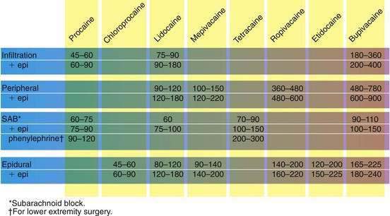
Not all procedures and physicians are created equal, at least regarding the amount of time needed to complete an operation. If anesthesiologists are to use regional techniques effectively, they must be able to choose a local anesthetic that lasts the right amount of time. To do this, they understand the local anesthetic timeline from the shorter-acting to the longer-acting agents (Fig. 1-1).
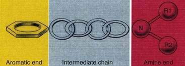
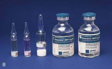
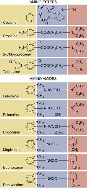
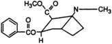
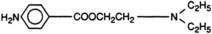
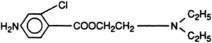
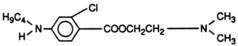
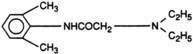
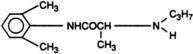
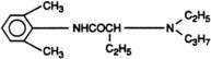
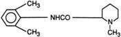
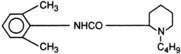
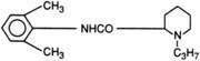
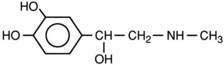
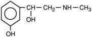
All local anesthetics share the basic structure of aromatic end, intermediate chain, and amine end (Fig. 1-2). This basic structure is subdivided clinically into two classes of drugs, the amino esters and the amino amides. The amino esters possess an ester linkage between the aromatic end and the intermediate chain. These drugs include cocaine, procaine, 2-chloroprocaine, and tetracaine (Figs. 1-3 and 1-4). The amino amides contain an amide link between the aromatic end and the intermediate chain. These drugs include lidocaine, prilocaine, etidocaine, mepivacaine, bupivacaine, and ropivacaine (see Figs. 1-3 and 1-4).

Needles, Catheters, and Syringes
In almost all disposable and reusable needles used in regional anesthesia, the bevel is cut on three planes. The design theoretically creates less tissue laceration and discomfort than the earlier styles did, and it limits tissue coring. Many needles that are to be used for deep injection during regional block incorporate a security bead in the shaft so that the needle can be easily retrieved on the rare occasions when the needle hub separates from the needle shaft. Figure 1-5 contrasts a blunt-beveled, 25-gauge needle with a 25-gauge “hypodermic” needle. Traditional teaching holds that the short-beveled needle is less traumatic to neural structures. There is little clinical evidence that this is so, and experimental data about whether sharp or blunt needle tips minimize nerve injury are equivocal.
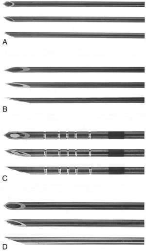
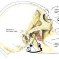
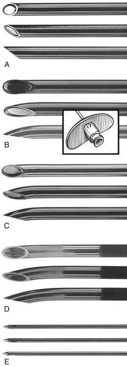
Figure 1-6 shows various spinal needles. The key to their successful use is to find the size and bevel tip that allow one to cannulate the subarachnoid space easily without causing repeated unrecognized puncture. For equivalent needle size, rounded needle tips that spread the dural fibers are associated with a lesser incidence of headache than are those that cut fibers. The past interest in very-small-gauge spinal catheters to reduce the incidence of spinal headache, with controllability of a continuous technique, faded during the controversy over lidocaine neurotoxicity.
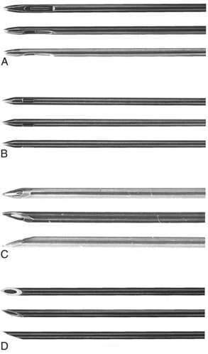
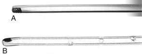
Figure 1-7 depicts epidural needles. Needle tip design is often mandated by the decision to use a catheter with the epidural technique. Figure 1-8 shows two catheters available for either subarachnoid or epidural use. Although each has advantages and disadvantages, a single–end-hole catheter appears to provide the highest level of certainty of catheter tip location at the time of injection, whereas a multiple–side-hole catheter may be preferred for continuous analgesia techniques.
Nerve Stimulators
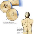
In recent years, use of nerve stimulators has increased from occasional use to common use and often critical importance. The growing emphasis on techniques that use either multiple injections near individual nerves or placement of stimulating catheters has provided impetus for this change. The primary impediment to successful use of a nerve stimulator in a clinical practice is that it is at least a three-handed or two-individual technique (Fig. 1-9), although there are devices allowing control of the stimulator current using a foot control, eliminating the need for a third hand or a second individual. In those situations requiring a second set of hands, correct operation of contemporary peripheral nerve stimulators is straightforward and easily taught during the course of the block. There are a variety of circumstances in which a nerve stimulator is helpful, such as in children and adults who are already anesthetized when a decision is made that regional block is an appropriate technique; in individuals who are unable to report paresthesias accurately; in performing local anesthetic administration on specific nerves; and in placement of stimulating catheters for anesthesia or postoperative analgesia. Another group that may benefit from the use of a nerve stimulator is patients with chronic pain, in whom accurate needle placement and reproduction of pain with electrical stimulation or elimination of pain with accurate administration of small volumes of local anesthetic may improve diagnosis and treatment.
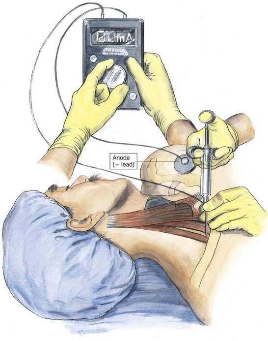
When nerve stimulation is used during regional block, insulated needles are most appropriate because the current from such needles results in a current sphere around the needle tip, whereas uninsulated needles emit current at the tip as well as along the shaft, potentially resulting in less precise needle location. A peripheral nerve stimulator should allow between 0.1 and 10 milliamperes (mA) of current in pulses lasting approximately 200 msec at a frequency of 1 or 2 pulses per second. The peripheral nerve stimulator should have a readily apparent readout of when a complete circuit is present, a consistent and accurate current output over its entire range, and a digital display of the current delivered with each pulse. This facilitates generalized location of the nerve while stimulating at 2 mA and allows refinement of needle positioning as the current pulse is reduced to 0.5 to 0.1 mA. The nerve stimulator should have the polarity of the terminals clearly identified because peripheral nerves are most effectively stimulated by using the needle as the cathode (negative terminal). Alternatively, if the circuit is established with the needle as anode (positive terminal), approximately four times as much current is necessary to produce equivalent stimulation. The positive lead of the stimulator should be placed in a site remote from the site of stimulation by connecting the lead to a common electrocardiographic electrode (see Fig. 1-9).
Ultrasonography (see Video 1: Introduction to Ultrasound on the Expert Consult Website)
American Society of Regional Anesthesiologists Recommendations

Wavelength and Frequency
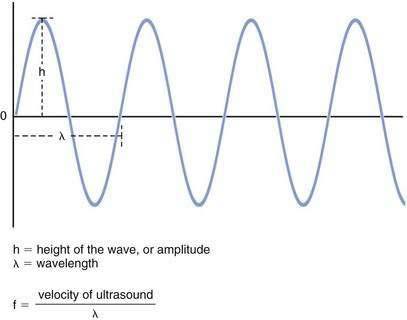
Ultrasound is a form of acoustic energy defined as the longitudinal progression of pressure changes (Fig. 1-10). These pressure changes consist of areas of compression and relaxation of particles in a given medium. For simplicity, an ultrasound wave is often modeled as a sine wave. Each ultrasound wave is defined by a specific wavelength (λ) measured in units of distance, amplitude (h) measured in decibels (dB), and frequency (f) measured in hertz (Hz) or cycles per second. Ultrasound is defined as a frequency of more than 20,000 Hz. Current transducers used for ultrasonography-guided regional anesthesia generate waves in the 3- to 13-MHz range (or 30,000 to 130,000 Hz).
Ultrasound Generation
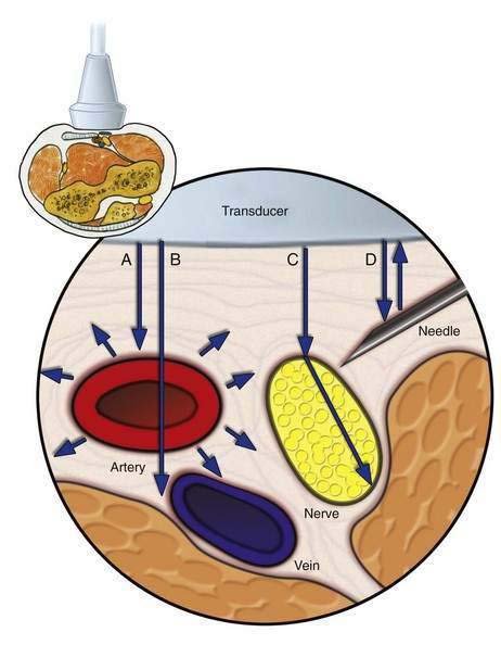
Ultrasound is generated when multiple piezoelectric crystals inside a transducer rapidly vibrate in response to an alternating electric current. Ultrasound then travels into the body where, on contact with various tissues, it can be reflected, refracted, and scattered (Fig. 1-11).
Clinical Issues Related to Physics
Resolution
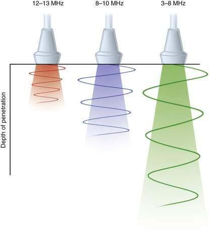
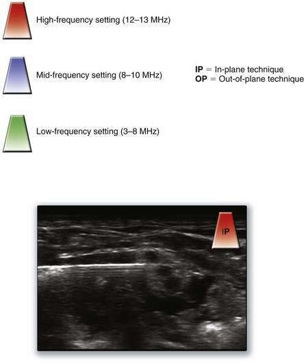
Resolution refers to the ability to clearly distinguish two structures lying beside one another. Although there are several different types of resolution, anesthesiologists are mostly concerned with lateral resolution (left–right distinction) and axial resolution (front–back distinction). Ultrasonography systems with higher frequencies have better resolution and can effectively discriminate closely spaced peripheral neural structures. However, because of a process known as attenuation, high-frequency ultrasound cannot penetrate into deep tissue (Fig. 1-12). Attenuation is the loss of ultrasound energy into the surrounding tissue, primarily as heat. For superficial blocks between 1 and 4 cm in depth, frequencies greater than 10 MHz are preferred. For blocks at depths greater than 4 cm, frequencies less than 8 MHz should result in adequate tissue penetration, with a predictable degradation in resolution.
Focus
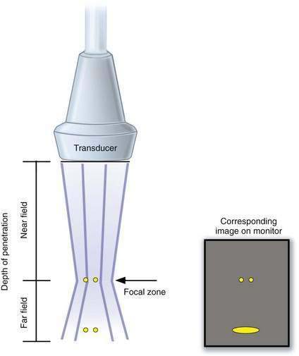
Although axial resolution is related simply to the frequency of ultrasound, lateral resolution also depends on beam thickness. Any maneuver that generates a narrow beam will increase the lateral resolution. Most ultrasonography machines have an electronic focus that generates a focal point (narrowest part of the beam) that can be placed directly over the target of interest. However, this increases the divergence of the beam beyond the region of the focus point (far field), resulting in image degradation of structures beyond this focal point. Thus, the beam focus should be placed at the level of the object that is being assessed to provide the clearest possible picture of the object (Fig. 1-13).

General Principles of an Ultrasonography-Guided Nerve Block
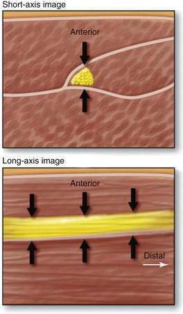
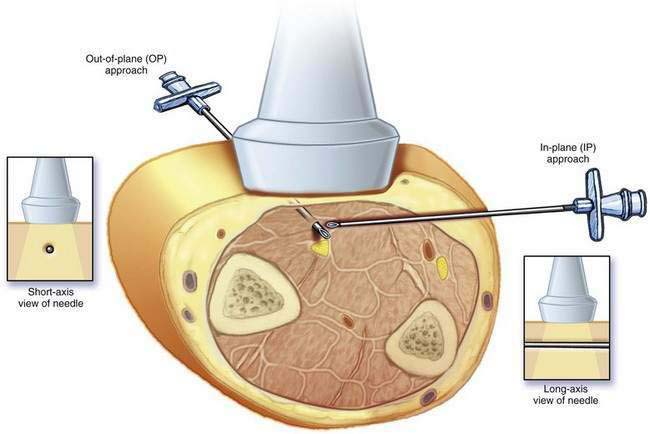
During ultrasonographic needle guidance, most nerves are imaged in cross-section (short axis). Alternatively, if the transducer is moved 90 degrees from the short-axis view, the long-axis view is generated. The short-axis view is generally preferred because it allows the operator to assess the lateromedial perspective of the target nerve, which is lost in the long-axis view (Fig. 1-14).
Two techniques have emerged regarding the orientation of the needle with respect to the ultrasound beam (Fig. 1-15). The in-plane approach generates a long-axis view of the needle, allowing full visualization of the shaft and tip of the needle. The out-of-plane view generates a short-axis view of the needle. One disadvantage of the in-plane approach is the challenge of maintaining needle imaging with a very thin ultrasound beam. A limitation of the out-of-plane view is that it generates a short-axis view of the block needle, which may be very hard to visualize. With the out-of-plane view, the operator cannot confirm that the needle tip (rather than part of the shaft) is being imaged, and therefore the needle location is often inferred from tissue movement or small injections of solution.
In the pertinent images in this text, we provide a key for the recommended starting setup for each block used with ultrasonographic guidance in a corner of the image (Fig. 1-16). (Remember that because of anatomic variability among patients, these base settings may have to be adjusted based on clinical and patient variables.)
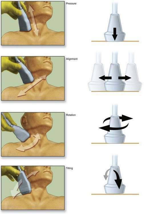
The primary objective of PART maneuvers is to optimize the amount of ultrasound that reflects off an object and returns to the transducer (Fig. 1-17).