[level-membership-for-orthopaedics-category]
Chapter 46 Intratunnel Tibial Fixation of Soft-Tissue Anterior Cruciate Ligament Grafts
Graft Sleeve and Tapered Screw
Introduction
Tibial fixation of soft-tissue anterior cruciate ligament (ACL) grafts remains challenging.1–5 Tibial fixation is challenging because of the lower bone mineral density of the proximal tibia, the fact that tibial fixation devices must resist shear forces applied parallel to the axis of the tibial bone tunnel, and the longer time required for soft-tissue grafts to heal within the bone tunnels.2,6 Tibial fixation of soft-tissue grafts using screws and ligament washers that anchor to the tibial cortex can address many of these issues; however, these implants are often prominent and often cause local skin irritation and pain, requiring a second operation for removal.5 Intratunnel tibial fixation of soft-tissue grafts using interference screws avoids the problem of prominent hardware; however, laboratory biomechanical studies have shown that the tensile properties of soft-tissue grafts fixed with interference screws are highly dependent on bone mineral density, and this fixation technique often results in low initial fixation strength and slippage under cyclical loading.2,4,5 The Graft Sleeve and Tapered Screw (GTS) System (Smith & Nephew Endoscopy, Andover, MA) intratunnel tibial fixation technique was developed to increase the failure load and stiffness and to decrease slippage of four-strand soft-tissue grafts.
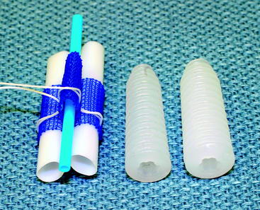
The GTS System is an intratunnel tibial fixation technique that positions a poly-L-lactic acid (PLLA) tapered, fine-pitch screw concentrically within a four-strand soft-tissue graft. The tapered screw features shorter thread distance, which enhances compression of the soft-tissue graft in cancellous bone. The GTS System consists of the tapered screw and a three-lumen, woven, nonabsorbable polypropylene (PPE) mesh graft sleeve that organizes the four-graft strands in the tibial tunnel. The graft sleeve prevents graft twisting during screw insertion; maximizes bone–tendon contact, which enhances healing; and provides better compression of each ligament strand against the bone tunnel wall while protecting the graft strands from screw damage (Fig. 46-1).
Basic Science
Biomechanical Testing
Biomechanical testing of the graft sleeve and tapered screw using human doubled gracilis and semitendinosus tendon (DGST) grafts has been performed in the proximal tibia of calf bone (2 years or younger) with bone mineral density similar to that of the proximal tibia in young humans.1,7 The tibia–DGST–graft sleeve complex was subjected to a 50N preload followed by cyclical loading between 50N and 250N at 1 Hz for 1000 cycles with the direction of tensile loading applied parallel to the axis of the tibial bone tunnel. Graft slippage was measured using a noncontact, three-camera, motion analysis system that allowed the position of retroreflective bone and graft markers to be recorded in three dimensions during cyclic loading. Mean graft slippage, in which graft slippage was defined as the change in position of the tendon marker relative to the bone marker under the 50N preload and after cyclical loading, was 1.14 ± 0.83 mm. The mean linear stiffness was 158 ± 31 N/mm, and the mean failure load was 736 ± 162 N, in which failure load was defined as the load when the load displacement curve substantially deviated from linear. The predominant mode of failure (60%) was pullout of the DGST tendons, graft sleeve, and tapered screw from the tibia. Comparison of the GTS System and the IntraFix Tibial Fastener (DePuy Mitek, Norwood, MA) using the just-mentioned testing protocol demonstrated no statistically significant differences in the cyclical and failure properties between the two devices.
Biocompatibility and Histology of Fixation Site Healing
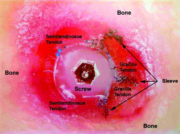
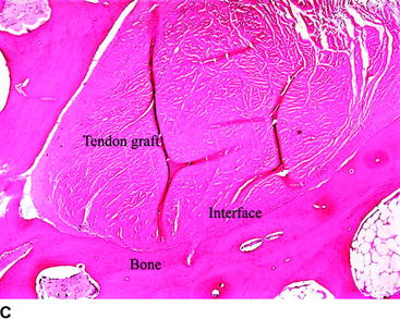
Biocompatibility of the PLLA screw and PPE graft sleeve has been studied in a sheep model.8 Gross histological examination demonstrated that implantation of the PLLA screw and polypropylene graft sleeve had no adverse effect on the articular cartilage. Microscopic analysis of the synovial fluid using polarized light failed to detect the presence of any polymeric debris. Signal intensity at the bone–tendon interface evaluated by computed tomography (CT) was used as an indicator of bone–tendon healing. CT slices in the axial plane demonstrated a progressive increase in healing at the bone–tendon interface over time. By 12 weeks a neocortex surrounded the tendon grafts. Based on the appearance of the signal intensity at the bone–tendon interface, the presence of the graft sleeve and tapered screw did not interfere with healing of the tendon to bone. No adverse reactions were noted related to the PLLA screw and PPE graft sleeve. Histological examination performed using a hard tissue technique in polymethylmethacrylate (PMMA) demonstrated that the PLLA screw compressed the tendons directly against the bone tunnel wall. These sections showed correct positioning of the PLLA screw in the PPE sleeve, as well as organization of the tendons in the PPE sleeve and bone tunnel to give a maximum bone–tendon interface (Fig. 46-2).
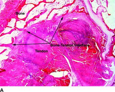
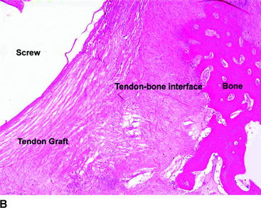
Healing at the bone–tendon and tendon–screw interface was evaluated on paraffin sections stained with hematoxylin and eosin (H&E) and trichrome stains. Bone–tendon healing progressed over time and was observed in all specimens. The tendon grafts were compressed against the adjacent bone as a result of the screw being placed in the central lumen of the graft sleeve. The bone–tendon interface was composed of loose connective tissue, fibroblastic cells and local areas of bone–tendon integration. There was no evidence of macrophage or foreign body reaction at the bone–tendon interface (Fig. 46-3). Connective tissue was noted to infiltrate throughout the PPE sleeve, and no significant difference was seen between areas where the sleeve and screw were present and areas in the proximal part of the bone tunnel where only the tendon grafts were present. The interface between the tendon graft and screw was composed of a thin layer of loose connective tissue with cellularity. There was no evidence of macrophage or foreign body reaction at the tendon–screw interface. In conclusion, histological analysis demonstrated the following:
Surgical Technique
Advantages of the Graft Sleeve and Tapered Screw
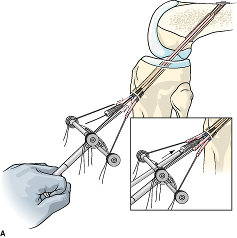
Compared with other intratunnel soft-tissue tibial fixation techniques, the advantages of the graft sleeve and tapered screw include consistent concentric insertion of the tapered screw, high screw insertion torque, uniform compression of the four-strand soft-tissue graft into the bone tunnel walls, and minimal rotation of the graft strands during screw insertion. Laboratory biomechanical testing has shown that these properties enhance initial graft fixation strength, stiffness, and resistance to slippage under cyclic loading.7,9 Finally, optimal surgical technique for implantation of the graft sleeve and tapered screw incorporates use of a mechanical tensioning device that equally tensions all four strands of the soft-tissue graft. Hamner et al10 have demonstrated in a laboratory biomechanical study that equal tensioning of all four strands of a four-strand hamstring tendon graft is necessary to maximize initial tensile strength and stiffness of the DGST graft.
Tibial Tunnel
A tibial tunnel length of 40 to 50 mm is optimal because this length range will allow the 30-mm-long tapered screw to be inserted flush with the tibial cortex, with there being no possibility that the screw will protrude into the intraarticular aspect of the knee joint. Setting the adjustable tibial aimer between 50 and 55 degrees will usually allow these tunnel lengths to be achieved. If the transtibial tunnel technique is used to drill the femoral tunnel, the starting position of the tibial guide pin must be located adjacent to the anterior fibers of the medial collateral ligament (MCL). This is necessary to achieve the correct tunnel angulation so that the femoral tunnel can be oriented at the 10-o’clock position. Laboratory biomechanical studies have demonstrated that single-tunnel ACL grafts placed at the 10-o’clock position provide better rotational control compared with ACL grafts placed at the 11-o’clock position.11 The starting location of the tibial guide pin is not critical if the femoral tunnel is drilled using the anteromedial portal technique.
A tight fit of the soft-tissue ACL graft in the bone tunnels is desirable to optimize tendon–bone healing.12 To ensure a tight fit, half-millimeter size drill bits are used to drill the bone tunnels. To prevent anterior drift of the tibial tunnel, a cannulated, rear entry–style drill is used to drill the tibial tunnel. Because attaching the graft sleeve to the DGST graft increases its diameter, it is necessary to overdrill the first 10 to 15 mm of the tibial tunnel by 1 mm greater than the measured size of the ACL graft. The remainder of the tibial tunnel is drilled using a drill size equal to the measured diameter of the DGST graft. Half-round or angled ACL chamfering rasps are used to smooth the intraarticular edge of the tibial tunnel to minimize graft abrasion. To ensure smooth passage of the graft sleeve into the tibial tunnel, it is important to clear soft tissue from around the edges of the tibial tunnel using an electrocautery pencil and a Cobb periosteal elevator.
Femoral Tunnel and Fixation
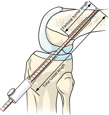
The graft sleeve and tapered screw can be used with any femoral fixation technique. However, because of its high strength, minimal slippage, and ease of use, we prefer femoral fixation with the Endobutton-CL.13 The femoral tunnel can be created using the transtibial tunnel or anteromedial portal techniques. The femoral guide pin is positioned at the 10-o’clock position along the sidewall of the lateral femoral condyle, and the Endobutton femoral tunnel and closed-end femoral socket are drilled in the usual fashion.14 An Endobutton depth gauge with adjustable knob (Smith & Nephew Endoscopy) is used to measure the femoral tunnel length and the total tunnel length (distance from the lateral femoral cortex to the superior margin of the anterior tibial cortex) (Fig. 46-4). These measurements are used to calculate the Endobutton-CL length and the location for attaching the graft sleeve on the gracilis tendon graft. If interference screw or cross-pin fixation techniques are used, the total tunnel length is measured from the end of the closed-end femoral socket to the anterior tibial cortex.
Application of the Graft Sleeve
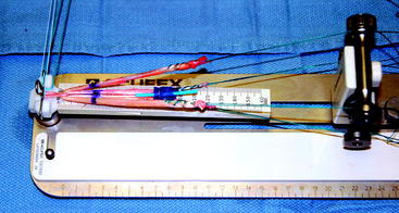
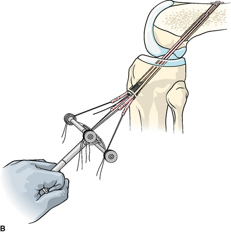
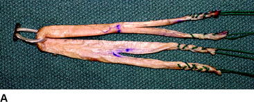
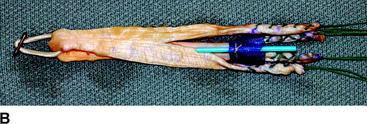
The sutures on the end of the gracilis tendon are threaded through the white, plastic threading tubes of the graft sleeve and the gracilis sutures attached to the lower knobs of the tensioner. It is important that the graft sleeve be attached to the gracilis tendon such that the cinching suture is positioned toward the Endobutton-CL. The white, plastic threading tubes are removed from the graft sleeve, and the sleeve is positioned on the gracilis at the previously marked total tunnel length. Because the graft sleeve has a tendency to slide distally on the gracilis tendon during graft passage, we have found it helpful to position the sleeve 10 mm closer to the Endobutton end of the graft. After verifying that the blue threading tube lies in the third lumen of the sleeve, the graft sleeve is attached to the gracilis tendon by securely tying the preinserted cinching suture. To provide additional security and to prevent the leading edge of the sleeve from puckering and impinging at the entrance of the tibial tunnel, we have found it helpful to loop and tie an additional #0 absorbable suture around the leading edge of the graft sleeve. The semitendinosus strands are equalized in length and the whipstitches are attached to the superior knobs of the tensioner. The semitendinosus strands should straddle the right/left sides of the top lumen on the graft sleeve and rest on the top surface of the lower two lumens containing the gracilis tendon (Fig. 46-5).
Tibial Fixation
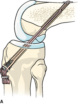
With the knee held at the desired flexion angle and 80N applied to the DGST graft, a 1.5-mm guidewire is inserted through the blue threading tube into the knee joint. The blue threading tube is removed, leaving the guidewire in place in the third lumen of the graft sleeve. If the diameter of the DGST graft is 6 to 8.5 mm, we recommend use of the 7- to 9-mm × 30-mm tapered screw. For larger graft sizes, the 8- to 10-mm × 30-mm tapered screw is used. The appropriate-sized tapered screw is inserted onto the BioRCI screwdriver (Smith & Nephew Endoscopy) and the screw advanced over the guidewire into the third lumen of the graft sleeve. While maintaining an 80N load on the DGST graft, the tapered screw is screwed into the graft sleeve and up into the tibial tunnel until the end of the screw is flush with the anterior tibial cortex (Fig. 46-6). Insertion of the tapered screw is usually accompanied by a “squeaking” feel and sound. Because the best bone quality is at or next to the anterior tibial cortex, inserting the tapered screw too deeply may decrease fixation strength.9
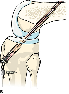
The fixation strength of any intratunnel fixation device is dependent on the local bone mineral density.1,2,5 If the surgeon believes that there was inadequate insertion torque during the insertion of the tapered screw or if the patient has soft bone, then we recommend that supplemental tibial fixation be used.3 Depending on the graft length, the protruding DGST tendons can be stapled below the tibial tunnel using a small barbed staple (Smith & Nephew Orthopaedics, Memphis, TN), or the sutures can be tied around a extra-small, nonbarbed staple or tibial fixation post (Smith & Nephew Endoscopy) (Fig. 46-7).
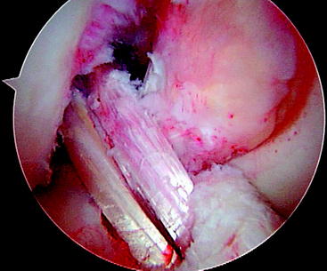
The stability and range of motion of the knee are checked. It is important to verify that the patient has full range of motion before leaving the operating room. The arthroscope is inserted into the knee, and graft tension and impingement are assessed. Our usual graft placement and tensioning technique results in the four strands of the DGST being maximally tight between 0 and 20 degrees, with the graft tension decreasing slightly as the knee is flexed to 90 degrees (Fig. 46-8). After confirming that the patient has a full range of motion and normal anterior laxity, the passing and flipping sutures are pulled out of the lateral thigh.
Postoperative Management
Follow-Up
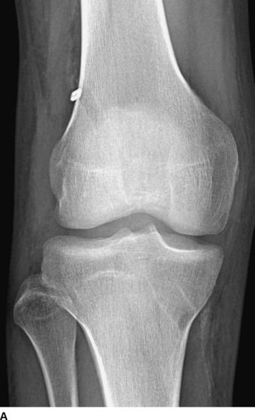
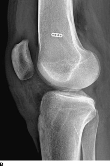
The patient is seen at 7 to 10 days for suture removal and postoperative radiographs (Fig. 46-9).
Rehabilitation
Our postoperative rehabilitation protocol is described in Table 46-1. The weight-bearing schedule is modified if a meniscus repair, microfracture, or other associated ligamentous surgery has been performed.
Table 46-1 Hamstring Anterior Cruciate Ligament Postoperative Rehabilitation Protocol
| Goals | Exercises |
|---|---|
| Phase I: Days 0–7 | |
| Control pain, inflammation, joint effusion, swelling | Knee CryoCuff, thigh-length TED stocking, elevation |
| Full passive extension equal to the opposite knee | Heel props, pull knee into hyperextension using elastic band |
| Achieve 90 degrees of flexion | Wall slides, gravity assisted flexion sitting on the edge of a table |
| Prevent quadriceps shutdown | EMS, quad isometrics, SLR, active-assisted extension 90–0 degrees |
| Prevent heel cord contracture | Ankle pumps, calf stretches with elastic bands |
| Gait training | Weight bearing as tolerated with knee immobilizer and crutches |
| Meniscus repair, revisions: ↑ 25% BW/week, wean off crutches end of week 4 | |
| Phase II: Weeks 1–2 | |
| Control inflammation, pain, joint effusion, swelling | Continue Phase I exercises |
| Maintain full symmetrical extension | Continue Phase I exercises |
| Achieve 100–125 degrees of flexion | Assisted flexion using opposite leg, wall slides, heel drags, rolling stool |
| Develop muscular control to safely wean off knee immobilizer and crutches | Continue Phase I exercises, mini-squats, toe raises, active extension 90–30 degrees |
| Protect hamstring donor site | Prevent sudden, forceful hamstring stretching with the knee and hip in extension, such as attempting to lean forward and put on socks and shoes or leaning forward to pick up an object off the floor |
| Phase III: Weeks 2–4 | |
| Maintain symmetrical extension | Heel props, prone heel hangs, lock knee out, “stand at attention” |
| Wean off knee immobilizer | Patients who fail to obtain symmetrical extension should be considered for extension splinting or a “drop-out” cast; discard immobilizer when able perform SLR without a quad lag |
| Wean off crutches | One crutch when able to bear 75% BW; discard crutches when full weight bearing and able to walk with normal heel–toe gait |
| Achieve 125–135 degrees flexion | Heel slides, sitting back on heels |
| Hamstring strengthening | Hamstring isometrics 0–90 degrees, pulling, rolling, rolling stool backwards |
| Quadriceps strengthening | Continue Phase II exercises, mini-squats with elastic band for resistance |
| Hip strengthening | Side-lying hip abduction, adjustable-angle hip machine |
| Proprioceptive training | Balance board double-leg stance |
| Aerobic conditioning | Elliptical machine |
| Phase IV: Weeks 4–6 | |
| Obtain full flexion | Heel slides, sitting back on heels |
| Continue quadriceps, hamstring, and hip strengthening | Mini-squats, leg press 50–0 degrees, front step-ups (control hip valgus), StairMaster backward, PNF, toe raises, seated leg curl machine 0–90 degrees |
| Proprioceptive training | Balance board double- and single-leg stance, add ball throws and catches |
| Aerobic conditioning | Stationary bike (adjust to protect PFJ), elliptical machine, pool exercises |
| Phase V: Weeks 6–12 | |
| Increase lower extremity strength and endurance | Increase intensity Phase IV exercises, high-speed (300–360 degrees/sec) isokinetics extension (90–30 degrees)/flexion (0–90 degrees), elliptical machine, StairMaster backward and forward, treadmill walking, pool exercises |
| Advance proprioceptive and perturbation training | Increase intensity of Phase IV exercises |
| Phase VI: Weeks 12–16 | |
| Increase quad and hamstring strength | Increase intensity of Phase IV exercises, mid-range (180–240 degrees/sec) isokinetics extension (90–30 degrees)/flexion (0–90 degrees) |
| Increase hamstring strength at high-flexion angles | Prone leg curls with elastic tubing and leg curl machine (90–120 degrees) |
| Jogging and running | Treadmill jogging and running, outdoor running on low-impact surface |
| Crossover drills | Lateral step-over, carioca drills |
| Phase VII: Weeks 16–24 | |
| Hard cutting and sports-specific drills | Figure-eight, circle run, plyometrics, hopping, jumping, sprinting |
| Return to noncontact sports at 4–5 months | Golf, tennis, biking, hiking |
| Return to full sports at 6 months (revisions, 9 months) | |
BW, Body weight; EMS, electrical muscle stimulation; PFJ, patellofemoral joint; PNF, proprioceptive neuromuscular facilitation; SLR, straight leg raises.
Use of the Graft Sleeve With Tibialis Tendon Allografts
Due to the potential issues of graft–tunnel mismatch and the lack of availability of bone–patellar tendon–bone (BPTB) allografts, double-stranded anterior and posterior tibial tendon (tibialis tendon) allografts have become an increasingly popular graft choice for ACL reconstruction. At the present time, bioabsorbable interference screws are most commonly used for tibial fixation of tibialis tendon allografts. For surgeons desiring improved initial fixation properties, it is possible to modify the ends of the tibialis tendon allograft to allow use of the graft sleeve and tapered screw. The tibialis tendon allograft is thawed and looped around a #5 suture, creating a double-stranded graft. The diameter of the doubled tibialis allograft is measured to the nearest half-millimeter as previously described. After drilling the tibial and femoral bone tunnels, the Endobutton depth gauge with adjustable knob is used to measure the femoral tunnel length, the total tunnel length, and the length of the tibial tunnel. The appropriate-length Endobutton-CL is selected, and the tibialis allograft is passed through the CL loop, creating a doubled tibialis tendon allograft. The total tunnel length is marked on the tibialis allograft as previously described. This mark serves to locate the position for attaching the graft sleeve. Using the total tunnel length mark as the starting point, a second mark that equals the length of the tibial tunnel is made toward the Endobutton end of the graft. The free ends of the tibialis tendon allograft are split in half with a 15 knife blade up to the tibial tunnel length mark, creating four tendon graft strands. The four graft strands are whipstitched using a #2 nonabsorbable suture. The graft sleeve is attached in the usual fashion to two strands of the doubled tibialis tendon allograft (Fig. 46-10). The tibialis tendon allograft is passed and fixed in the femur as previously described. The knee is cycled 30 times with a preload of 100N applied to the graft strands. While maintaining an 80N load on the tibialis tendon allograft, the tapered screw is screwed into the graft sleeve and up into the tibial tunnel until the end of the screw is flush with the anterior tibial cortex.
Pearls and Pitfalls of the Technique
Results
We have performed more than 30 hamstring ACL reconstructions using graft sleeve and tapered screw tibial fixation since the device became clinically available. There have been no infections, recurrent effusions, or other complications related to the device. The early objective stability and clinical results are similar to those we reported using the IntraFix tibial fastener.14 However, due to the higher insertion torque and the tighter fit in the tibial tunnel, we have used supplemental tibial fixation less frequently.
1 Brand JC, Pienkowski D, Steenlage E, et al. Interference screw fixation strength of a quadrupled hamstring tendon graft is directly related to bone mineral density and insertion torque. Am J Sports Med. 2000;28:705-710.
2 Brand JC, Weiler A, Caborn DNM, et al. Graft fixation in cruciate ligament reconstruction. Am J Sports Med. 2000;28:761-774.
3 Hill PF, Russell VJ, Salmon LJ, et al. The influence of supplementary tibial fixation on anterior laxity measurements after anterior cruciate ligament reconstruction with hamstring tendons in female patients. Am J Sports Med. 2005;33:94-101.
4 Kousa P, Jarvinen TLN, Vihavainen M, et al. The fixation strength of six hamstring tendon graft fixation devices in anterior cruciate ligament reconstruction. Part II: tibial site. Am J Sports Med. 31, 2003. 182–174
5 Magen HE, Howell SM, Hull ML. Structural properties of six tibial fixation methods for anterior cruciate ligament soft tissue grafts. Am J Sports Med. 1999;27:35-43.
6 Rodeo SA, Arnoczky SP, Torzilli PA, et al. Tendon healing in a bone tunnel: a biomechanical and histological study in the dog. J Bone Joint Surg. 1993;75A:1795-1803.
7 Hecker AT, Blough R. GTS Sleeve vs. IntraFix Fastener: a biomechanical comparison of initial fixation properties. Report on file at Smith & Nephew Endoscopy, Andover, MA
8 Cotton NJ, Blough RA. Histological evaluation of the GTS Sleeve/GTS Tapered Screw intratunnel tibial fixation system in an ovine model. Report on file at Smith & Nephew Endoscopy, Andover, MA
9 Harvery AR, Thomas NP, Amis AA. The effect of screw length and position on fixation of four-stranded hamstring grafts for anterior cruciate ligament reconstruction. Knee. 2002;10:97-102.
10 Hamner DL, Brown CH, Steiner ME, et al. Hamstring tendon grafts for reconstruction of the anterior cruciate ligament: biomechanical evaluation of the use of multiple strands and tensioning techniques. J Bone Joint Surg. 1999;81A:549-557.
11 Loh JC, Fukuda Y, Tsuda E, et al. Knee stability and graft function following anterior cruciate ligament reconstruction: comparison between 11 o’clock and 10 o’clock femoral tunnel positions. Arthroscopy. 2003;19:297-304.
12 Greis PE, Burks RT, Bachus K, et al. The influence of tendon length and fit on the strength of a tendon-bone tunnel complex: a biomechanical and histologic study in the dog. Am J Sports Med. 2001;29:493-497.
13 Brown CH, Wilson DR, Hecker AT, et al. Graft-bone motion and tensile properties of hamstring and patellar tendon anterior cruciate ligament femoral graft fixation under cyclic loading. Arthroscopy. 2004;20:922-935.
14 Brown CH, Sklar JH, Darwich N. Endoscopic anterior cruciate ligament reconstruction using autogenous doubled gracilis and semitendinosus tendons. Tech Knee Surg. 2004;3:215-237.
[/level-membership-for-orthopaedics-category][not-level-membership-for-orthopaedics-category]
Chapter 46 Intratunnel Tibial Fixation of Soft-Tissue Anterior Cruciate Ligament Grafts
Graft Sleeve and Tapered Screw
Introduction
Tibial fixation of soft-tissue anterior cruciate ligament (ACL) grafts remains challenging.1–5 Tibial fixation is challenging because of the lower bone mineral density of the proximal tibia, the fact that tibial fixation devices must resist shear forces applied parallel to the axis of the tibial bone tunnel, and the longer time required for soft-tissue grafts to heal within the bone tunnels.2,6 Tibial fixation of soft-tissue grafts using screws and ligament washers that anchor to the tibial cortex can address many of these issues; however, these implants are often prominent and often cause local skin irritation and pain, requiring a second operation for removal.5 Intratunnel tibial fixation of soft-tissue grafts using interference screws avoids the problem of prominent hardware; however, laboratory biomechanical studies have shown that the tensile properties of soft-tissue grafts fixed with interference screws are highly dependent on bone mineral density, and this fixation technique often results in low initial fixation strength and slippage under cyclical loading.2,4,5 The Graft Sleeve and Tapered Screw (GTS) System (Smith & Nephew Endoscopy, Andover, MA) intratunnel tibial fixation technique was developed to increase the failure load and stiffness and to decrease slippage of four-strand soft-tissue grafts.
The GTS System is an intratunnel tibial fixation technique that positions a poly-L-lactic acid (PLLA) tapered, fine-pitch screw concentrically within a four-strand soft-tissue graft. The tapered screw features shorter thread distance, which enhances compression of the soft-tissue graft in cancellous bone. The GTS System consists of the tapered screw and a three-lumen, woven, nonabsorbable polypropylene (PPE) mesh graft sleeve that organizes the four-graft strands in the tibial tunnel. The graft sleeve prevents graft twisting during screw insertion; maximizes bone–tendon contact, which enhances healing; and provides better compression of each ligament strand against the bone tunnel wall while protecting the graft strands from screw damage (Fig. 46-1).
Basic Science
Biomechanical Testing
Biomechanical testing of the graft sleeve and tapered screw using human doubled gracilis and semitendinosus tendon (DGST) grafts has been performed in the proximal tibia of calf bone (2 years or younger) with bone mineral density similar to that of the proximal tibia in young humans.1,7 The tibia–DGST–graft sleeve complex was subjected to a 50N preload followed by cyclical loading between 50N and 250N at 1 Hz for 1000 cycles with the direction of tensile loading applied parallel to the axis of the tibial bone tunnel. Graft slippage was measured using a noncontact, three-camera, motion analysis system that allowed the position of retroreflective bone and graft markers to be recorded in three dimensions during cyclic loading. Mean graft slippage, in which graft slippage was defined as the change in position of the tendon marker relative to the bone marker under the 50N preload and after cyclical loading, was 1.14 ± 0.83 mm. The mean linear stiffness was 158 ± 31 N/mm, and the mean failure load was 736 ± 162 N, in which failure load was defined as the load when the load displacement curve substantially deviated from linear. The predominant mode of failure (60%) was pullout of the DGST tendons, graft sleeve, and tapered screw from the tibia. Comparison of the GTS System and the IntraFix Tibial Fastener (DePuy Mitek, Norwood, MA) using the just-mentioned testing protocol demonstrated no statistically significant differences in the cyclical and failure properties between the two devices.
Biocompatibility and Histology of Fixation Site Healing
Biocompatibility of the PLLA screw and PPE graft sleeve has been studied in a sheep model.8 Gross histological examination demonstrated that implantation of the PLLA screw and polypropylene graft sleeve had no adverse effect on the articular cartilage. Microscopic analysis of the synovial fluid using polarized light failed to detect the presence of any polymeric debris. Signal intensity at the bone–tendon interface evaluated by computed tomography (CT) was used as an indicator of bone–tendon healing. CT slices in the axial plane demonstrated a progressive increase in healing at the bone–tendon interface over time. By 12 weeks a neocortex surrounded the tendon grafts. Based on the appearance of the signal intensity at the bone–tendon interface, the presence of the graft sleeve and tapered screw did not interfere with healing of the tendon to bone. No adverse reactions were noted related to the PLLA screw and PPE graft sleeve. Histological examination performed using a hard tissue technique in polymethylmethacrylate (PMMA) demonstrated that the PLLA screw compressed the tendons directly against the bone tunnel wall. These sections showed correct positioning of the PLLA screw in the PPE sleeve, as well as organization of the tendons in the PPE sleeve and bone tunnel to give a maximum bone–tendon interface (Fig. 46-2).
Healing at the bone–tendon and tendon–screw interface was evaluated on paraffin sections stained with hematoxylin and eosin (H&E) and trichrome stains. Bone–tendon healing progressed over time and was observed in all specimens. The tendon grafts were compressed against the adjacent bone as a result of the screw being placed in the central lumen of the graft sleeve. The bone–tendon interface was composed of loose connective tissue, fibroblastic cells and local areas of bone–tendon integration. There was no evidence of macrophage or foreign body reaction at the bone–tendon interface (Fig. 46-3). Connective tissue was noted to infiltrate throughout the PPE sleeve, and no significant difference was seen between areas where the sleeve and screw were present and areas in the proximal part of the bone tunnel where only the tendon grafts were present. The interface between the tendon graft and screw was composed of a thin layer of loose connective tissue with cellularity. There was no evidence of macrophage or foreign body reaction at the tendon–screw interface. In conclusion, histological analysis demonstrated the following:
Surgical Technique
Advantages of the Graft Sleeve and Tapered Screw
Compared with other intratunnel soft-tissue tibial fixation techniques, the advantages of the graft sleeve and tapered screw include consistent concentric insertion of the tapered screw, high screw insertion torque, uniform compression of the four-strand soft-tissue graft into the bone tunnel walls, and minimal rotation of the graft strands during screw insertion. Laboratory biomechanical testing has shown that these properties enhance initial graft fixation strength, stiffness, and resistance to slippage under cyclic loading.7,9 Finally, optimal surgical technique for implantation of the graft sleeve and tapered screw incorporates use of a mechanical tensioning device that equally tensions all four strands of the soft-tissue graft. Hamner et al10 have demonstrated in a laboratory biomechanical study that equal tensioning of all four strands of a four-strand hamstring tendon graft is necessary to maximize initial tensile strength and stiffness of the DGST graft.
Tibial Tunnel
A tibial tunnel length of 40 to 50 mm is optimal because this length range will allow the 30-mm-long tapered screw to be inserted flush with the tibial cortex, with there being no possibility that the screw will protrude into the intraarticular aspect of the knee joint. Setting the adjustable tibial aimer between 50 and 55 degrees will usually allow these tunnel lengths to be achieved. If the transtibial tunnel technique is used to drill the femoral tunnel, the starting position of the tibial guide pin must be located adjacent to the anterior fibers of the medial collateral ligament (MCL). This is necessary to achieve the correct tunnel angulation so that the femoral tunnel can be oriented at the 10-o’clock position. Laboratory biomechanical studies have demonstrated that single-tunnel ACL grafts placed at the 10-o’clock position provide better rotational control compared with ACL grafts placed at the 11-o’clock position.11 The starting location of the tibial guide pin is not critical if the femoral tunnel is drilled using the anteromedial portal technique.
A tight fit of the soft-tissue ACL graft in the bone tunnels is desirable to optimize tendon–bone healing.12
[/not-level-membership-for-orthopaedics-category]
