[level-membership-for-neurosurgery-category]
Chapter 175 Intraoperative Imaging
Plain Film Radiography
Even when the correct level is identified, localization errors may occur. For example, localization in the lumbar spine typically involves placing a marker on a spinous process and obtaining a lateral radiograph. Although the correct spinous process may be visualized on the film, continued surgical dissection down to the level of the lumbar canal may cause the surgeon to easily drift to an adjacent lumbar segment above or below the desired level. Placement of a marker at the level of the lumbar lamina in addition to the marker on the spinous process can help prevent this error.
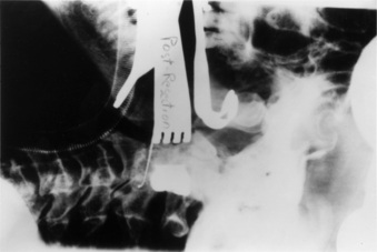
In addition to localization of the spinal level, plain radiography can be used in isolated instances to assess the extent of neural decompression. This technique is particularly useful during transoral decompressive procedures. It involves placing a radiopaque contrast medium into the decompressed site and obtaining a lateral radiograph. The radiograph will show the extent of the decompression and can be compared with a preoperative study demonstrating the neural compression. If the configuration and location of the contained contrast medium does not approximate the configuration and location of the epidural compression on the preoperative studies, the surgical site can be modified until a satisfactory decompression of the neural elements is achieved (Fig. 175-1).
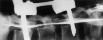
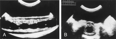
Plain radiography can also be used in conjunction with intraoperative myelography to determine the extent of canal decompression.1 In the setting of a thoracolumbar burst fracture decompressed through a dorsolateral approach, radiopaque dye can be placed in the subarachnoid space by a small-gauge spinal needle to assess the adequacy of the surgical decompression. A lateral radiograph is taken and the relationship of the dye to the ventral spinal cord can be assessed (Fig. 175-2).
Fluoroscopy
Fluoroscopy is used when real-time imaging or multiple images of the spine are required during surgery. Fluoroscopic images are generated with a lower radiation dose than that for standard radiography. A camera records the image and displays it on a television monitor. The images can be recorded on x-ray film, cinefluoradiography film, or videotape.2
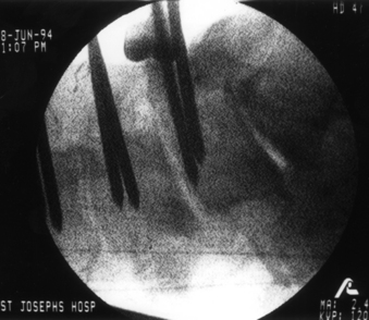
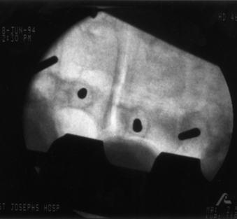
The primary use of fluoroscopy in spine surgery is to facilitate the optimal placement and positioning of spine fixation screws, interbody cages, or arthroplasty devices and to monitor the injection of methyl methacrylate into osteoporotic vertebral body fractures. Fluoroscopy can provide the surgeon with real-time imaging of the spinal column in several planes depending on the positioning of the fluoroscope’s C-arm. When used for the insertion of pedicle screws, the C-arm can be positioned to provide a lateral view of the spinal column. This shows the sagittal (rostrocaudal) orientation of a pedicle marker or screw (Fig. 175-3). By rotating the C-arm from the lateral position toward the AP position, an oblique view of the spinal column can be obtained. This view demonstrates the position of a pedicle marker or screw in relationship to a cross-sectional view of each pedicle. If the correct entry point and trajectory in both the sagittal and axial planes has been properly selected, the oblique fluoroscopic view will demonstrate these markers within the cortical margins of the individual pedicles (Fig. 175-4). When the correct entry point and trajectories have been confirmed, the markers can be removed and the pedicle screws inserted along the same path.
When used for cervical screw fixation (e.g., ventral odontoid screw fixation), an AP as well as a lateral view may be required. This can be obtained by alternating the position of a single C-arm unit from the lateral to the AP position or by using two separate fluoroscopy machines with arms positioned 90 degrees with respect to each other.3
Fluoroscopy has also been used for ventral cervical plate instrumentation procedures to assist in the positioning and placement of the fixation plates and screws.4 However, the lower cervical and upper thoracic regions can frequently be difficult to visualize because of image obstruction by the patient’s shoulders. This problem can be addressed by placing an interscapular roll beneath the patient and taping the shoulders down to the table or by using wrist slings to pull down on the patient’s arms during imaging.
The primary disadvantage of intraoperative fluoroscopy is the exposure of the surgical team to repeated amounts of low-dose ionizing radiation. Several studies have attempted to quantify the amount of occupational radiation exposure to health-care professionals under different and real clinical scenarios.5–9 These studies have typically demonstrated that the radiation exposure to hands, eyes, head and neck, and body during fluoroscopically assisted procedures is well below the recommended values for annual allowable occupational radiation exposure as outlined by the International Commission on Radiological Protection.10 However, the health-related risks of this chronic exposure to radiation remains relatively unknown and may not be realized for years.
Unlike other fluoroscopically assisted musculoskeletal procedures (e.g., intramedullary femoral nailing), the techniques and instruments used for pedicle fixation bring the surgeon’s hands very close to the primary area of exposure.11,12 The amount of radiation exposure needed to achieve adequate visualization of the lumbar spine is greater than that for other anatomic sites.13 Rampersaud et al. reported on the radiation exposure occurring during the placement of thoracolumbar pedicle screws.14 Pedicle screws were placed into six cadaver specimens using fluoroscopy. Dosimeter badges and rings were placed on the surgeon’s neck, torso, and dominant hand. Radiation exposure to these sites was quantified.
Ninety-six pedicle screws were placed with an average of 8.5 fluoroscopic images taken per screw. The average exposure time per screw was 9.3 seconds. The results of this study demonstrated that fluoroscopically assisted pedicle screw fixation exposes the spine surgeon to significantly greater radiation levels than other, nonspinal musculoskeletal procedures involving the use of fluoroscopy. The radiation exposure to the dominant hand was noted to be as high as 10 to 12 times the amount of hand exposure experienced in other procedures. The greatest level of exposure was noted on the side ipsilateral to the beam source due to backscatter radiation. This study emphasizes the need for appropriate lead shielding, including the use of a thyroid shield and leaded glasses. The use of radiation attenuation gloves resulted in a 33% decrease in dose rate to the hand. Using limited, pulsed-image acquisition and maintaining a safe distance (3–4 feet) from the radiation source also helped reduce the dosage to negligible levels.14 This study confirmed that spine surgeons who regularly use fluoroscopy should monitor their annual radiation dose.
Ultrasonography
The application of ultrasonography to spine surgery was first reported in 1982.15 Like fluoroscopy, ultrasonography provides continuous and real-time imaging. However, unlike fluoroscopy, which only provides images of the bony spinal column, ultrasonography can image the adjacent neural and soft tissue structures as well.
Diagnostic ultrasound scanners consist of a scan head containing transducers that convert electrical energy to mechanical or sound energy. To obtain a sonogram the scan head of the ultrasound probe is placed against a contact surface. A short ultrasonic pulse is generated by the transducers and transmitted into the contact surface. This pulse travels continuously into the medium until it strikes another surface or encounters a change in acoustic impedance. Acoustic impedance, the product of the density of a material and the velocity of the sound wave, depends not only on tissue density but also on the actual composition and internal structure of a tissue substance.16
When the ultrasound pulse strikes a surface, some of the energy is reflected back to the transducer and some of the energy continues forward. Structures that reflect most or all of the ultrasound pulses striking them, specifically air and bone, prevent the imaging of structures behind them. A reflected ultrasonic pulse returns to the scan head and hits the transducer. The shape of the crystal in the transducer is changed, inducing a voltage across it. This voltage is recorded—its amplitude dependent on the strength of the reflection that contacts the transducer face. The location within the tissue from which the reflection came can easily be calculated once the speed of sound in the tissue being scanned and the interval of time between the generation of the impulse and the reception of the reflected wave are known.
Ultrasonography can be used to localize a variety of lesions within the spinal canal. It is effective for localizing and characterizing intramedullary spinal cord tumors as well as intradural and extramedullary tumors. Ultrasonography can be used before opening the dura to visualize the extent of the tumor and to localize specific areas of interest such as a cyst within the tumor. The images guide the opening of the dura and can often direct the surgeon to a particular location to start the myelotomy and exploration.17 When a cystic tumor such as a hemangioma is present, ultrasonography can help identify the specific mural nodule of the tumor.18
Edema proximal or distal to the tumor also causes widening of the cord seen on ultrasonography and can create confusion in determining the absolute limits of the tumor. However, in most cases, the tumor border is well defined and the edema is less echogenic than the tumor.19
In the setting of syringomyelia, ultrasonography can be used to localize the maximal extent of the syrinx as well as to identify any small septae present (Fig. 175-5).18 If a drainage catheter is placed into the syrinx, ultrasonography can be used to assess the degree of collapse of the cavity and determine whether additional catheters are needed.
Ultrasonography has also been used in the setting of vertebral body fractures or dislocations to assess the spinal canal following a decompressive procedure. This is particularly useful in the thoracic and thoracolumbar areas when a dorsolateral approach is used to access ventral and ventrolateral epidural compression. Following removal of the lamina, the ultrasound probe can be placed over the dorsal dura and the extent of the ventral decompression assessed.20,21
Image-Guided Spinal Navigation
The development of image-guided technology for spine surgery was influenced by the difficulties of intraoperative spatial orientation associated with surgery for complex spine disorders.22,23 The 3D anatomy of the spinal column can present challenges for even the most experienced surgeon. Standard dorsal surgical approaches expose only a portion of the spinal column at a given level. Although this partial exposure is not problematic for most laminectomy or discectomy procedures, it can be limiting in the setting of complex spinal column disorders such as fractures, neoplasms, or deformities.
Several studies have shown the unreliability of routine radiography in assessing pedicle screw placement in the lumbosacral spine. The rate of penetration of the pedicle cortex by an inserted screw ranges from 21% to 31% in these studies.24–26 However, Steinmann et al., using an image-based technique for pedicle screw placement that combined axial CT of cadaver spine specimens with fluoroscopy, was able to demonstrate a reduction of this screw insertion error rate to 5.5%.27
The application of image-guided navigational technology to spine surgery provides 3D and multiplanar views of image data to improve the surgeon’s “visualization” of the spinal anatomy. This image data is provided in near-real time and can be manipulated to show every aspect of the intraoperative spinal anatomy through any selected point in the surgical field.22,23,28–30
Navigational Technique
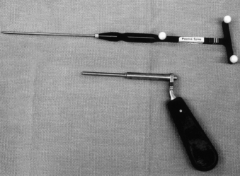
The primary components of an IGSN include an image-processing computer workstation interfaced with a two-camera optical localizer (Fig. 175-6). Customized navigational probes with three to four small reflective spheres attached in a known arrangement serve as the tools that link the surgeon to the navigational system (Fig. 175-7). The optical localizer camera system emits infrared energy toward the surgical field, where it is captured by the spheres on the probe and reflected back to the camera. The spatial orientation of the reflected light is passed on to the computer workstation, which can then use mathematical principles of localization by triangulation to localize and track not only the exact position of the probe’s tip but also the position of any anatomic structure in the surgical field on which the probe tip rests.
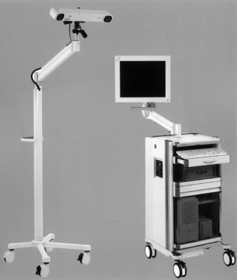
FIGURE 175-6 Image-guided navigation system. Image-processing computer workstation (right) and an infrared camera (left).
Bone landmarks on the exposed surface of the spinal column provide the frame of reference necessary for image-guided navigation. Specifically, any anatomic landmark that can be identified during surgery and in the preoperative image data set can be used as a reference point. Typically, for spine surgery, the reference points are the tips of the spinous process and transverse processes at each spinal level to be instrumented, although other bony landmarks such as facet joints or prominent osteophytes can also be used.22,23,28–30
Alternatively, the surgeon can perform the registration process by creating a surface map of the exposed spinal anatomy. This technique involves placing the probe on multiple nondiscreet points on the exposed and debrided surface in the surgical field. The positional information of these points is transferred to the workstation, and a topographic map of the selected anatomy is created and “matched” to the patient’s CT data set. This surface mapping technique is typically more time-consuming and inherently less accurate than the paired point registration technique.30
Registration can have the greatest effect on navigational accuracy. Registration accuracy depends on the surgeon carefully selecting the correct reference points or performing the contour mapping process. If properly performed, registration will allow for the display of reformatted, multiplanar CT or MRI images to assist the surgeon with orientation to the unexposed spinal anatomy.23
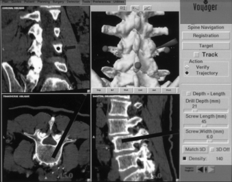
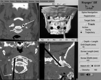
Once the registration process is completed, the surgeon can place the navigational probe on any exposed point in the operative field and the workstation will automatically generate three reformatted images through the selected point. The three planar images are oriented perpendicular to each other in relationship to the long axis of the probe. For pedicle screw fixation, these three reformatted images will be the corresponding axial, coronal, and sagittal images through a selected point. On each reformatted image, a cursor or trajectory line marks the position of the navigational probe in the surgical field. The diameter of the cursor and the width of the trajectory line can be adjusted in proportion to the selected screw diameter. The length of the trajectory line relative to the imaged spine is displayed in millimeters, providing for accurate screw length selection (Fig. 175-8). As the surgeon moves the probe through the surgical field, each planar image updates immediately to show the probe’s orientation to the spinal column and provides the surgeon with an optimal orientation to the pertinent spinal anatomy and to the precise screw entry point and trajectory.
When applied to screw fixation of the spinal column, IGSN reduces or eliminates the need for intraoperative imaging.22,23,28–30 It can facilitate the optimal placement of screws within the spinal column. However, unlike intraoperative fluoroscopy, IGSN does not provide true real-time imaging. It does not show changes in the spinal anatomy as they occur. The system functions as a confirmation tool to assist the surgeon in identifying the pedicle and relating its position and orientation to the exposed spinal anatomy. It is an alternative method to the more conventional means of interpreting 2D images of the spine, relating them to the surgeon’s knowledge of the pertinent anatomy, and estimating the location of the pedicle. It is not intended to function as a substitute for an understanding of the appropriate spinal anatomy and the indications and techniques for insertion of pedicle screws.
Applications of this technology to spine surgery have proven IGSN to be a practical and extremely useful alternative and adjunct to conventional intraoperative imaging. It has been used routinely for pedicle screw fixation in the lumbosacral as well as the thoracic spine. It is very useful for placing transarticular screws at the C1-2 level (Fig. 175-9) and for providing optimal orientation to spinal anatomy during transoral surgery and during ventral thoracolumbar surgery.22,23,28–30 Additionally, it serves as a highly effective image manipulation system allowing the surgeon to scroll through CT images in any selected plane prior to and during surgery. This feature allows the surgeon to better conceptualize the complex 3D anatomy of the spinal column than is possible by the standard method of viewing multiple 2D image sheets.
Fluoroscopic Navigation
Fluoroscopic navigation is the combination of standard fluoroscopy with image-guided navigational technology. It was developed to address the difficulties of some earlier image-guided systems that typically took much longer to use than standard fluoroscopy.31 Although standard fluoroscopy is employed with this technique, the amount of fluoroscopic time is significantly reduced.
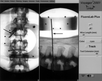
With the patient in position prior to surgery, an AP and lateral fluoroscopic view of the pertinent spinal anatomy is obtained. This is done with a customized reference frame attached to the C-arm. The frame serves to superimpose a specific reference grid on the two images obtained. The navigational workstation can then take the two images with the superimposed grid and relate the spatial position of the imaged anatomy to a navigational probe. As the navigational probe is placed on the patient’s anatomy, a corresponding trajectory line and cursor can then be superimposed on the lateral and AP images, respectively (Fig. 175-10).
Brunberg J.A., Gabrielsen T., Rubin J., et al. Diagnostic imaging technology. In: Crockard H., Hayward R., Hoff J.T., editors. Neurosurgery: the scientific basis of clinical practice. ed 2. Boston: Blackwell Scientific; 1992:758-786.
Chandler W.F., Knake J.E., McGillicuddy J.E., et al. Intraoperative use of real-time ultrasonography in neurosurgery. J Neurosurg. 1982;57:157-163.
Foley K.T., Simon D.A., Rampersaud Y.R. Virtual fluoroscopy: computer-assisted fluoroscopic navigation. Spine (Phila Pa 1976). 2001;26(4):347-351.
Kalfas I.H. Image-guided spinal navigation: principles and clinical applications. In: Ozgur B., Benzel E., Garfin S., editors. Minimally invasive approaches to the spine. St Louis: Springer; 2009:7-22.
Murphy M.A., McKenzie R.L., Kormos D.W., Kalfas I.H. Frameless stereotaxis for the insertion of lumbar pedicle screws: a technical note. J Clin Neurosci. 1994;1(4):257-260.
Rampersaud Y.R., Foley K.T., Shen A.C., et al. Radiation exposure to the spine surgeon during fluoroscopically assisted pedicle screw insertion. Spine (Phila Pa 1976). 2000;25:2637-2645.
1. Walker J., Gillespie R., Davis J., Dawson W. Water-soluble contrast medium for intraoperative evaluation of anterior cervical discectomy: technical note. Neurosurgery. 1988;68:491-492.
2. Brunberg J.A., Gabrielsen T., Rubin J., et al. Diagnostic imaging technology. In: Crockard H., Hayward R., Hoff J.T., editors. Neurosurgery: the scientific basis of clinical practice. ed 2. Boston: Blackwell Scientific; 1992:758-786.
3. Grob D., Jeanneret B., Aebi M., Markwalder T. Atlanto-axial fusion with transarticular screw fixation. J Bone Joint Surg [Br]. 1991;73:972-976.
4. Caspar W. Anterior cervical fusion and interbody stabilization with the trapezial osteosynthetic plate technique. Aesculap Scientific Information Leaflet S-039. Burlingame, CA: Aesculap Instruments Corp; 1986.
5. Boone J.M., Levine J.C. Radiation exposure to angiographers under different fluoroscopic imaging conditions. Radiology. 1991;180:861-865.
6. Boone J.M., Pfeiffer D.F., Strauss K.J. A survey of fluoroscopic exposure rates: APM Task Group No. 11 Report. Am Assoc Phys Med. 1993;20:789-794.
7. McKerry M.H. Study of radiation doses to personnel in a cardiac catheterization laboratory. Health Phys. 1996;70:563-567.
8. Riley S.A. Radiation exposure from fluoroscopy during orthopedic surgical Procedures. Clinical Orthop Relat Res. 1989;248:257-260.
9. Sugarman J.D., Adam I., Bunker T.D. Radiation dosage during AO locking femoral nailing. Injury. 1988;19:336-338.
10. Recommendations of the International Commission on Radiological Protection. International Commission on Radiological Protection. Publication. 60, 1991.
11. Giachino A.A., Cheng M. Irradiation of the surgeon during pinning of femoral fractures. J Bone Joint Surg [Br]. 1980;62:227-229.
12. Mehlman C.T., DiPasquale T.G. Radiation exposure to the orthopedic surgical team during fluoroscopy: how far away is far enough? J Orthop Trauma. 1987;11:392-398.
13. Little J.B., Taveras J.M., editors. Radiology: diagnosis, imaging, intervention. Philadelphia: JB Lippincott, 1992.
14. Rampersaud Y.R., Foley K.T., Shen A.C., et al. Radiation exposure to the spine surgeon during fluoroscopically assisted pedicle screw insertion. Spine (Phila Pa 1976). 2000;25:2637-2645.
15. Chandler W.F., Knake J.E., McGillicuddy J.E., et al. Intraoperative use of real-time ultrasonography in neurosurgery. J Neurosurg. 1982;57:157-163.
16. Dohrmann G.J., Rubin J.M. Intraoperative diagnostic ultrasound. In: Wilkins R.H., Rengachary S.S., editors. Neurosurgery. New York: McGraw-Hill; 1985:457-463.
17. Platt J.M., Rubin J.M., Bowerman R.A., et al. Intraoperative sonographic characterization of a cystic intramedullary spinal cord lesion appearing as solid. AJNR Am J Neuroradiol. 1988;9:614.
18. Platt J.M., Rubin J.M., Chandler W.F., et al. Intraoperative spinal sonography in the evaluation of intramedullary tumors. J Ultrasound Med. 1988;7:317-325.
19. Sanders W.P., Ausman J.I., Dujovny M., et al. Ultrasonic features of two cases of spinal cord hemangioblastoma. Surg Neurol. 1986;26:453-456.
20. McGahan J.P., Benson D., Chehrazi B., et al. Intraoperative sonographic monitoring of reduction of thoracolumbar burst fractures. Am J Radiol. 1985;145:1229-1232.
21. Montalvo B.M., Quencer R.M., Green B.A., et al. Intraoperative sonography in spinal trauma. Radiology. 1984;153:125-134.
22. Kalfas I.H., Kormos D.W., Murphy M.A., et al. Application of frameless stereotaxy to pedicle screw fixation of the spine. J Neurosurg. 1995;83:641-647.
23. Murphy M.A., McKenzie R.L., Kormos D.W., Kalfas I.H. Frameless stereotaxis for the insertion of lumbar pedicle screws: a technical note. J Clin Neurosci. 1994;1(4):257-260.
24. George D.C., Krag M.H., Johnson C.C., et al. Hole preparation technique for transpedicle screws: effect on pull-out strength from human cadaveric vertebrae. Spine (Phila Pa 1976). 1991;16:181-184.
25. Gertzbein S.D., Robbins S.E. Accuracy of pedicle screw placement in vivo. Spine (Phila Pa 1976). 1990;15:11-14.
26. Weinstein J.N., Spratt K.F., Spengler D., et al. Spinal pedicle fixation: reliability and validity of roentgenogram-based assessment and surgical factors on successful screw placement. Spine (Phila Pa 1976). 1988;13:1012-1018.
27. Steinmann J.C., Herkowitz H.O., El-Kommos H., Wesolowski D.P. Spinal pedicle fixation: confirmation of an image-based technique for screw placement. Spine (Phila Pa 1976). 1993;18:1856-1861.
28. Kalfas I.H. Frameless stereotaxy assisted spinal surgery. In: Renganchary S.S., editor. Neurosurgery operative color atlas. Park Ridge, IL: AANS Publications; 2000:123-134.
29. Kalfas I.H. Image-guided spinal navigation. Contemp Spine Surg. 2004;5:1-8.
30. Kalfas I.H. Image-guided spinal navigation: principles and clinical applications. In: Ozgur B., Benzel E., Garfin S., editors. Minimally invasive. approaches to the spine. St Louis: Springer; 2009:7-22.
31. Foley K.T., Simon D.A., Rampersaud Y.R. Virtual fluoroscopy: computer-assisted fluoroscopic navigation. Spine (Phila Pa 1976). 2001;26(4):347-351.
[/level-membership-for-neurosurgery-category][not-level-membership-for-neurosurgery-category]
Chapter 175 Intraoperative Imaging
Plain Film Radiography
Even when the correct level is identified, localization errors may occur. For example, localization in the lumbar spine typically involves placing a marker on a spinous process and obtaining a lateral radiograph. Although the correct spinous process may be visualized on the film, continued surgical dissection down to the level of the lumbar canal may cause the surgeon to easily drift to an adjacent lumbar segment above or below the desired level. Placement of a marker at the level of the lumbar lamina in addition to the marker on the spinous process can help prevent this error.
In addition to localization of the spinal level, plain radiography can be used in isolated instances to assess the extent of neural decompression. This technique is particularly useful during transoral decompressive procedures. It involves placing a radiopaque contrast medium into the decompressed site and obtaining a lateral radiograph. The radiograph will show the extent of the decompression and can be compared with a preoperative study demonstrating the neural compression. If the configuration and location of the contained contrast medium does not approximate the configuration and location of the epidural compression on the preoperative studies, the surgical site can be modified until a satisfactory decompression of the neural elements is achieved (Fig. 175-1).
Plain radiography can also be used in conjunction with intraoperative myelography to determine the extent of canal decompression.1 In the setting of a thoracolumbar burst fracture decompressed through a dorsolateral approach, radiopaque dye can be placed in the subarachnoid space by a small-gauge spinal needle to assess the adequacy of the surgical decompression. A lateral radiograph is taken and the relationship of the dye to the ventral spinal cord can be assessed (Fig. 175-2).
Fluoroscopy
Fluoroscopy is used when real-time imaging or multiple images of the spine are required during surgery. Fluoroscopic images are generated with a lower radiation dose than that for standard radiography. A camera records the image and displays it on a television monitor. The images can be recorded on x-ray film, cinefluoradiography film, or videotape.2
The primary use of fluoroscopy in spine surgery is to facilitate the optimal placement and positioning of spine fixation screws, interbody cages, or arthroplasty devices and to monitor the injection of methyl methacrylate into osteoporotic vertebral body fractures. Fluoroscopy can provide the surgeon with real-time imaging of the spinal column in several planes depending on the positioning of the fluoroscope’s C-arm. When used for the insertion of pedicle screws, the C-arm can be positioned to provide a lateral view of the spinal column. This shows the sagittal (rostrocaudal) orientation of a pedicle marker or screw (Fig. 175-3). By rotating the C-arm from the lateral position toward the AP position, an oblique view of the spinal column can be obtained. This view demonstrates the position of a pedicle marker or screw in relationship to a cross-sectional view of each pedicle. If the correct entry point and trajectory in both the sagittal and axial planes has been properly selected, the oblique fluoroscopic view will demonstrate these markers within the cortical margins of the individual pedicles (Fig. 175-4). When the correct entry point and trajectories have been confirmed, the markers can be removed and the pedicle screws inserted along the same path.
When used for cervical screw fixation (e.g., ventral odontoid screw fixation), an AP as well as a lateral view may be required. This can be obtained by alternating the position of a single C-arm unit from the lateral to the AP position or by using two separate fluoroscopy machines with arms positioned 90 degrees with respect to each other.3
Fluoroscopy has also been used for ventral cervical plate instrumentation procedures to assist in the positioning and placement of the fixation plates and screws.4 However, the lower cervical and upper thoracic regions can frequently be difficult to visualize because of image obstruction by the patient’s shoulders. This problem can be addressed by placing an interscapular roll beneath the patient and taping the shoulders down to the table or by using wrist slings to pull down on the patient’s arms during imaging.
The primary disadvantage of intraoperative fluoroscopy is the exposure of the surgical team to repeated amounts of low-dose ionizing radiation. Several studies have attempted to quantify the amount of occupational radiation exposure to health-care professionals under different and real clinical scenarios.5–9 These studies have typically demonstrated that the radiation exposure to hands, eyes, head and neck, and body during fluoroscopically assisted procedures is well below the recommended values for annual allowable occupational radiation exposure as outlined by the International Commission on Radiological Protection.10 However, the health-related risks of this chronic exposure to radiation remains relatively unknown and may not be realized for years.
Unlike other fluoroscopically assisted musculoskeletal procedures (e.g., intramedullary femoral nailing), the techniques and instruments used for pedicle fixation bring the surgeon’s hands very close to the primary area of exposure.11,12 The amount of radiation exposure needed to achieve adequate visualization of the lumbar spine is greater than that for other anatomic sites.13 Rampersaud et al. reported on the radiation exposure occurring during the placement of thoracolumbar pedicle screws.14 Pedicle screws were placed into six cadaver specimens using fluoroscopy. Dosimeter badges and rings were placed on the surgeon’s neck, torso, and dominant hand. Radiation exposure to these sites was quantified.
Ninety-six pedicle screws were placed with an average of 8.5 fluoroscopic images taken per screw. The average exposure time per screw was 9.3 seconds. The results of this study demonstrated that fluoroscopically assisted pedicle screw fixation exposes the spine surgeon to significantly greater radiation levels than other, nonspinal musculoskeletal procedures involving the use of fluoroscopy. The radiation exposure to the dominant hand was noted to be as high as 10 to 12 times the amount of hand exposure experienced in other procedures. The greatest level of exposure was noted on the side ipsilateral to the beam source due to backscatter radiation. This study emphasizes the need for appropriate lead shielding, including the use of a thyroid shield and leaded glasses. The use of radiation attenuation gloves resulted in a 33% decrease in dose rate to the hand. Using limited, pulsed-image acquisition and maintaining a safe distance (3–4 feet) from the radiation source also helped reduce the dosage to negligible levels.14 This study confirmed that spine surgeons who regularly use fluoroscopy should monitor their annual radiation dose.
Ultrasonography
The application of ultrasonography to spine surgery was first reported in 1982.15 Like fluoroscopy, ultrasonography provides continuous and real-time imaging. However, unlike fluoroscopy, which only provides images of the bony spinal column, ultrasonography can image the adjacent neural and soft tissue structures as well.
[/not-level-membership-for-neurosurgery-category]
