[level-membership-for-anesthesiology-category]
Chapter 10 Intraoperative Echocardiography
Few areas in cardiac anesthesia have developed as rapidly as the field of intraoperative echocardiography. In the early 1980s, when transesophageal echocardiography (TEE) was first used in the operating room, its main application was the assessment of global and regional left ventricular (LV) function. Since that time there have been numerous technical advances: biplane and multiplane probes; multifrequency probes; enhanced scanning resolution; color flow, pulsed wave, and continuous wave Doppler; automatic edge detection; Doppler tissue imaging; three-dimensional (3D) reconstruction; and digital image processing. With these advances, the number of clinical applications of TEE has markedly increased. The common applications of TEE include (1) assessment of valvular anatomy and function, (2) evaluation of the thoracic aorta, (3) detection of intracardiac defects, (4) detection of intracardiac masses, (5) evaluation of pericardial effusions, (6) detection of intracardiac air and clots, and (7) assessment of biventricular systolic and diastolic function. In many of these evaluations, TEE is able to provide unique and critical information that was not previously available in the operating room (Box 10-1).
BASIC CONCEPTS

Imaging Techniques
Contrast Echocardiography
Contrast echocardiography has been used to image intracardiac shunts, valvular incompetence, and pericardial effusions. In addition, LV injections of hand-agitated microbubble solutions have been used to identify semiquantitative LV endocardial edges, cardiac output, and valvular regurgitation (Box 10-2).
Contrast agents are microbubbles, consisting of a shell surrounding a gas. Initial contrast agents were agitated free air in either a saline or blood/saline solution. These microbubbles were large and unstable, so they were unable to cross the pulmonary circulation; they were effective only for right-sided heart contrast. Because of their thin shell, the gas quickly leaked into the blood with resultant dissolution of the microbubble. Agents with a longer persistence were subsequently developed.1
COMPLICATIONS
Complications resulting from intraoperative TEE can be separated into two groups: injury from direct trauma to the airway and esophagus and indirect effects of TEE (Box 10-3). In the first group, potential complications include esophageal bleeding, burning, tearing, dysphagia, and laryngeal discomfort. Many of these complications could result from pressure exerted by the tip of the probe on the esophagus and the airway. Although in most patients even maximal flexion of the probe will not result in pressure above 17 mm Hg, occasionally, even in the absence of esophageal disease, pressures greater than 60 mm Hg will result.
ANATOMY AND TRANSESOPHAGEAL ECHOCARDIOGRAPHY VIEWS
Multiplane Transesophageal Echocardiography Probe Manipulation: Descriptive Terms and Technique
The process of obtaining a comprehensive intraoperative multiplane TEE examination begins with a fundamental understanding of the terminology and technique for probe manipulation (Fig. 10-1).2 Efficient probe manipulation minimizes esophageal injury and facilitates the process of acquiring and sweeping through 2D image planes. Horizontal imaging planes are obtained by moving the TEE probe up and down (proximal and distal) in the esophagus at various depths relative to the incisors (upper esophageal: 20 to 25 cm; midesophageal: 30 to 40 cm; transgastric: 40 to 45 cm; deep transgastric: 45 to 50 cm) (Table 10-1). Vertical planes are obtained by manually turning the probe to the patient’s left or right. Further alignment of the imaging plane can be obtained by manually rotating one of the two control wheels on the probe handle, which flexes the probe tip to the left or right direction or in the anterior or posterior plane. Multiplane probes may further facilitate interrogation of complex anatomic structures, such as the mitral valve (MV), by allowing up to 180 degrees of axial rotation of the imaging plane without manual probe manipulation.
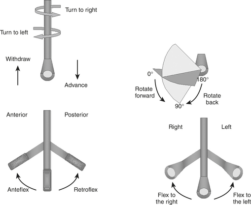
Table 10-1 The Comprehensive Intraoperative Multiplane Transesophageal Echocardiographic Examination
| Probe Tip Depth (from lips): Upper Esophageal (20 to 25 cm) | |
| View | Aortic arch: long axis |
| Multiplane angle range | 0° |
| Anatomy imaged | Aortic arch; left brachiocephalic vein; left subclavian and carotid arteries; right brachiocephalic artery |
| Clinical utility | |
The Comprehensive Intraoperative Transesophageal Echocardiography Examination: Imaging Planes and Structural Analysis
Left and Right Ventricles
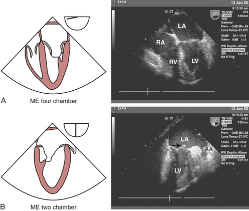
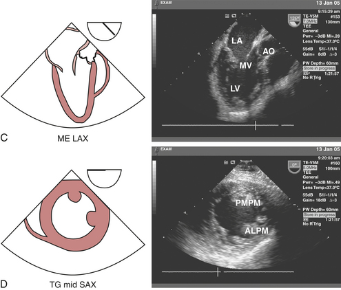
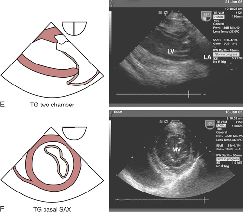
The LV should be carefully examined for global and regional function using multiple transducer planes, depths, and rotational and angular orientations (Fig. 10-2). Analysis of segmental function is based on a qualitative visual assessment that includes the following grading system of both LV wall thickness and motion (endocardial border excursion) during systole: 1 = normal (>30% thickening); 2 = mild hypokinesis (10% to 30% thickening); 3 = severe hypokinesis (<10% thickening); 4 = akinesis (no thickening); 5 = dyskinesis (paradoxical motion). The midesophageal (ME) four-chamber view at 0 to 20 degrees (see Fig. 10-2A) and two-chamber view at approximately 80 to 100 degrees (see Fig. 10-2B) enable visualization of the septal and lateral as well as the inferior and anterior segments at the basal, mid, and apical level segments, respectively. The ME long-axis (LAX) view at 120 to 160 degrees (see Fig. 10-2C) allows evaluation of the remaining anteroseptal and posterior LV segments. Because the LV is usually oriented inferiorly to the true horizontal plane, slight retroflexion of the probe tip may be required to minimize LV foreshortening. The transgastric (TG) mid short-axis (SAX) view at 0 to 20 degrees (see Fig. 10-2D) is the most commonly used view for monitoring LV function because it allows a midpapillary assessment of the LV segments supplied by the corresponding coronary arteries (right [RCA], left circumflex [CX], and left anterior descending [LAD]). This view also enables qualitative and quantitative evaluation of pericardial effusions. Advancing or withdrawing the probe at the transgastric depth enables LV evaluation at the respective apical and basal levels (TG basal short-axis view; see Fig. 10-2F). Further evaluation of the LV can be obtained at the midpapillary transgastric depth by rotating the probe forward to the TG two-chamber view (80 to 100 degrees) (see Fig. 10-2E) and TG long-axis view (90 to 120 degrees) (see Fig. 10-2J).
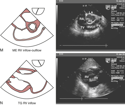
Right ventricular (RV) regional and global function can be assessed from the ME four-chamber view (see Fig. 10-2A), which allows visualization of the septal and free walls. Although a formal segmental scheme has not been developed for the RV free wall, regional assessment of the septum can be performed. Turning the probe to the right and advancing slightly from the midesophageal depth allows visualization of the tricuspid valve (TV), coronary sinus (CS), and RV apex. Rotating the probe between 60 and 90 degrees reveals the ME RV inflow-outflow view (see Fig. 10-2M), in which the RA, TV, inferior RV free wall, right ventricular outflow tract (RVOT), pulmonic valve (PV), and main pulmonary artery (PA) can be viewed “wrapping around” the centrally oriented AV. This view often allows optimal Doppler beam alignment to evaluate the TV and can also be helpful for directing PA catheter floating and positioning. The TG mid short-axis view(see Fig. 10-2D) displays the crescent-shaped, thinner-walled RV to the left of the LV (i.e., to the right side of the LV).
Mitral Valve
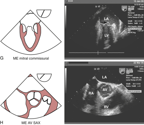
The echocardiographic evaluation of the MV requires a thorough assessment of its leaflets (anterior and posterior), annulus, and the subvalvular apparatus (chordae tendineae, papillary muscles, and adjacent LV walls) to locate lesions and define the etiology and severity of the pathophysiology. The mitral leaflets can be further divided into posterior leaflet scallops—lateral (P1), middle (P2), and medial (P3)—that correspond with respective anterior leaflet sections—lateral third (A1), middle third (A2), and medial third (A3). The leaflets are united at the anterolateral and posteromedial commissures. The ME four-chamber view (see Fig. 10-2A) displays the larger appearing anterior leaflet (A3) to the left of the posterior leaflet (P1). Anteflexing the probe provides imaging of the anterior aspect of the MV, while gradual advancement of the probe and retroflexion shifts the image plane to the posterior aspect of MV. Maintaining the probe at the ME depth and rotating the multiplane angle forward to 60 to 70 degrees develops the ME mitral commissural view (see Fig. 10-2G) in which A2 is flanked by P1 on the right and P3 on the left, giving A2 the appearance of a “trap door” as it moves in and out of the imaging plane throughout the cardiac cycle.
Aortic Valve, Aortic Root, and Left Ventricular Outflow
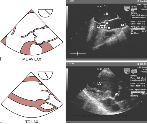
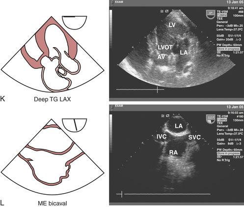
The three cusps of the semilunar AV are best visualized simultaneously in the ME AV short-axis view (see Fig. 10-2H), which is obtained by rotating the probe forward to 30 to 60 degrees. The noncoronary cusp is superior, lying adjacent to the atrial septum, the right cusp is inferiorly imaged, and the left cusp lies to the right pointing in the direction of the LA appendage (LAA). This view permits planimetry of the AV orifice, evaluation of congenital anomalies of the AV (e.g., bicuspid AV), and qualitative assessment of aortic regurgitation (AR) when color flow Doppler imaging is used. The ME AV long-axis view (see Fig. 10-2I) can be obtained at the same depth while rotating the probe to 120 to 160 degrees, allowing for visualization of the left ventricular outflow tract (LVOT), AV annulus and leaflets (right and either noncoronary or left), sinuses of Valsalva, sinotubular junction, and proximal ascending aorta. This view is particularly useful for evaluating AR with color flow Doppler imaging, systolic anterior motion of the MV, and proximal aortic pathology (dissections, aneurysms). Rotating the probe back to 90 to 120 degrees and advancing into the stomach to the transgastric level develops the TG long-axis view (see Fig. 10-2J). In this view, the LVOT and AV are oriented to the right and inferiorly in the displayed image, thereby providing an optimal window for parallel Doppler beam alignment for the assessment of flows and pressure gradients (aortic stenosis, hypertrophic obstructive cardiomyopathy). Rotating the probe back further to 0 to 20 degrees, advancing deep into the stomach and anteflexing the tip so that it lies adjacent to the LV apex allows for the development of the deep TG long-axis view (see Fig. 10-2K), which also provides optimal Doppler beam alignment for measuring transaortic valve and LVOT flow velocities and may also provide an additional window for assessing flows through muscular VSDs and LV apical pathology (thrombus, aneurysms).
Tricuspid Valve
The echocardiographic evaluation of the TV requires a thorough assessment of its three leaflets (anterior, posterior, and septal), annulus, chordae tendineae, papillary muscles, and corresponding RV walls. In the ME four-chamber view (see Fig. 10-2A), the septal TV leaflet is displayed on the right side and the posterior TV leaflet on the left side of the annulus. Rotating the multiplane angle to 60 to 90 degrees develops the ME RV inflow-outflow view (see Fig. 10-2M), which displays the posterior TV leaflet on the left side of the image and the anterior TV leaflet on the right side of the image adjacent to the AV. The TG RV inflow view (see Fig. 10-2N) is obtained by advancing the probe into the stomach and rotating to 100 to 120 degrees. This view is ideal for visualizing the chordae tendineae and papillary muscles in the RV. Rotating back to the TG mid short-axis view at 0 to 20 degrees and slightly withdrawing the probe provides a cross-sectional view of the TV, displaying the anterior leaflet in the far field, the posterior leaflet to the left in the near field, and the septal leaflet on the right side of the image.
Pulmonic Valve and Pulmonary Artery
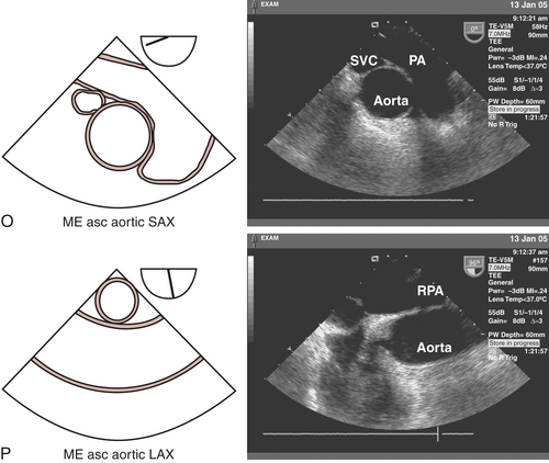
The pulmonic valve (PV) is a trileaflet, semilunar valve. The ME AV short-axis view (see Fig. 10-2H) displays the transition between the RVOT and PV. Rotating the probe back toward 0 degrees and withdrawing slightly develops the ME ascending aortic short-axis view (see Fig. 10-2O), displaying the transition between the RV and main PA and its bifurcation. Although the right PA is usually easy to visualize by turning the probe to the right, the left PA is often obscured by the interposing, air-filled, left main-stem bronchus. This view can be used in the Doppler echocardiographic assessment of PV pathophysiology because of the parallel alignment of the beam relative to the flow and can also be used to locate pulmonary emboli. The ME RV inflow-outflow (see Fig. 10-2M) view can also be used to assess RV, PV, and main PA.
Left Atrium, Left Atrial Appendage, Pulmonary Veins, and Atrial Septum
The LA is the closest cardiac structure to the TEE probe when positioned in the esophagus. Consequently, the LA is usually easily displayed in the superior aspect of the 2D image sector. The ME four-chamber view (see Fig. 10-2A) displays the LA almost in its entirety with the LAA oriented to its superior and lateral aspect when the probe is slightly withdrawn. The muscular ridges of the pectinate muscles within the LAA should not be confused with thrombi. Slight further withdrawal of the probe and turning it to the left allows the left upper pulmonary vein (LUPV) to be imaged as it enters the LA from the anterior to posterior direction separated from the lateral border of the LAA by the “warfarin ridge.” In contrast to the LUPV, which is usually optimally aligned for parallel Doppler beam alignment, the left lower pulmonary vein (LLPV) enters the LA just below the LUPV in a lateral-to-medial direction and is more perpendicularly aligned. Pulmonary venous Doppler flow-velocity profiles are useful for the qualitative and quantitative assessment of LV diastolic function. Turning the probe to the right at this depth reveals the right upper pulmonary vein (RUPV) entering the LA in an anterior-to-posterior direction. The right lower pulmonary vein (RLPV) can sometimes be visualized as it enters perpendicular to the long axis of the LA, by slightly advancing the probe.
The interatrial septum (IAS), consisting of thicker limbus regions flanking the thin fossa ovalis, can also be imaged in the ME four-chamber view. Benign lipomatous hypertrophy of the IAS must be distinguished from pathologic lesions such as atrial myxomas. The patency of the IAS and presence of PFO or congenital atrial septal defects (ASDs) should be assessed with Doppler echocardiography and intravenous injections of agitated saline or other contrast agents. Advancing and rotating the probe to 80 to 100 degrees develop the ME two-chamber view (see Fig. 10-2B), which allows for further imaging of the LA from left to right. The LAA and LUPV can be seen by turning the probe slightly to the left. Rotating the probe to the right at this level and adjusting the multiplane angle to 80 to 110 degrees develop the ME bicaval view (see Fig. 10-2L), which delineates the superior vena cava (SVC) entering the RA to the right of the image and the inferior vena cava (IVC) entering from the left. The IAS can be seen in the middle of the image separating the LA and RA.
Right Atrium and Coronary Sinus
The RA can be most easily visualized in the ME four-chamber view (see Fig. 10-2A) by turning the probe to the patient’s right side. In this view, the entire RA can be visualized for size, overall function, and the presence of masses (thrombi, tumors). Rotating the multiplane angle to 80 to 110 degrees develops the ME bicaval view (see Fig. 10-2L), which displays the RA and its internal structures (eustachian valve, Chiari network, crista terminalis). The SVC can be imaged entering the RA on the right, superior to the right atrial appendage (RAA), and the IVC enters the RA on the left of the display. Advancing and turning the probe to the right allow for a qualitative evaluation of the intrahepatic segment of the IVC and hepatic veins. Pacemaker electrodes and central venous catheters for hemodynamic monitoring or cardiopulmonary bypass (CPB) can be easily imaged in this view.
The coronary sinus (CS) lies posteriorly in the atrioventricular groove, emptying into the RA at the inferior extent of the atrial septum. The CS can be viewed in long axis entering the RA just superior to the tricuspid annulus by advancing and slightly retroflexing the probe from ME four-chamber view (see Fig. 10-2A). The CS can be imaged cross-sectionally in short axis in the ME two-chamber (see Fig. 10-2B) view in the upper left of the display. Turning the probe to the left in this view often allows visualization of the CS in long axis as it traverses the atrioventricular groove. The CS and thebesian valve can also be visualized in the ME bicaval view (see Fig. 10-2L) on the upper right of the image as the CS enters the RA at an obtuse angle, by turning the probe to leftward simultaneously with retro- and leftward flexion. Echocardiographic visualization of the CS can be useful for directing the placement of CS catheters used for CPB with retrograde cardioplegia.
Thoracic Aorta
The proximal and mid-ascending thoracic aorta can be visualized in short axis in the ME ascending aortic short-axis view (see Fig. 10-2O). Advancing and withdrawing the probe should enable visualization of the thoracic aorta from the sinotubular junction to a point 4 to 6 cm superior to the AV and allow inspection for aneurysms and dissections. Rotating the multiplane angle to 100 to 150 degrees develops the ME ascending aortic long-axis view (see Fig. 10-2P), which optimally displays the parallel anterior and posterior walls for measuring proximal and mid-ascending aortic diameters. This view can also be obtained from the ME AV long-axis view (see Fig. 10-2I) by slightly withdrawing and turning the probe to the left.
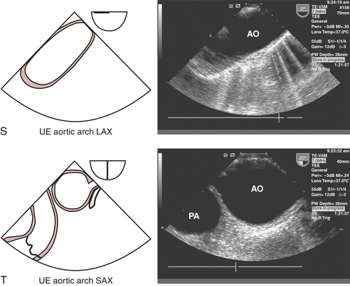
TEE imaging of the aortic arch is often obscured by the interposing, air-filled trachea. The most optimal views of the aortic arch are obtained by withdrawing the probe from the ME ascending aortic short-axis view at 0 degrees (see Fig. 10-2O) and rotating to the left to obtain the upper esophageal aortic arch long-axis view (see Fig. 10-2S), which displays the proximal arch followed by the mid arch, the great vessels (brachiocephalic, left carotid and left subclavian artery), and distal arch before it joins the proximal descending thoracic aorta imaged in cross section. Alternatively, rotating the probe to 90 degrees develops the upper esophageal aortic arch short-axis view view (see Fig. 10-2T). Turning the probe to the left, this view delineates the transition of the distal arch with the proximal descending thoracic aorta. Turning the probe to the right and slightly withdrawing it allows for the mid arch and great vessels to be imaged on the right side of the screen, followed by the distal ascending aorta when the probe is subsequently advanced and rotated forward to 120 degrees (ME ascending aortic long-axis view [see Fig. 10-2P]). Epiaortic scanning may be particularly useful for assessing the extent of ascending aortic and arch pathology (e.g., aneurysms, dissection, atherosclerosis) to determine cross-clamping and cannulation sites for CPB.
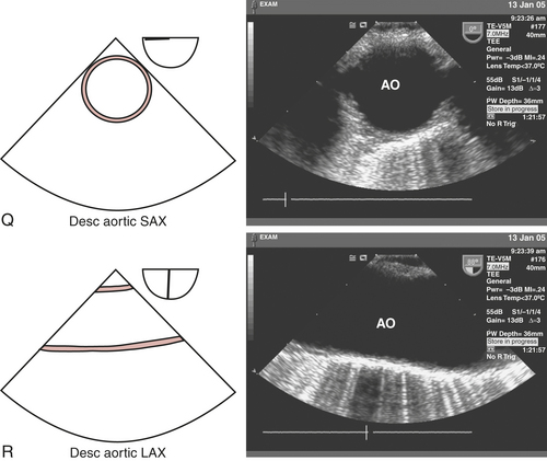
A short-axis image of the descending thoracic aorta is obtained by turning the probe leftward from the ME four-chamber view (see Fig. 10-2A) to produce the descending aortic short-axis view (see Fig. 10-2Q). Rotating the multiplane angle of the probe from 0 degrees to 90 to 110 degrees produces a long-axis image, the descending aortic long-axis view (see Fig. 10-2R). The descending thoracic aorta should be interrogated in its entirety, beginning at the distal aortic arch by continually advancing the probe and turning slightly to the left until the celiac and superior mesenteric arteries are visualized branching tangentially from the anterior surface of the abdominal aorta when the probe is in the stomach. Thorough examination of the descending thoracic aorta may be necessary to evaluate the distal extent of an aneurysm or dissection. In addition, the descending aortic short- and long-axis views can be useful for confirming appropriate intra-aortic balloon positioning.
CLINICAL APPLICATIONS
Myocardial Ischemia Monitoring
Diagnosis of Ischemia
The precise sequence of functional changes that occur in the myocardium after interruption of flow has been studied in models of acute ischemia, including percutaneous transluminal coronary angioplasty (PTCA). Abnormalities in diastolic function usually precede abnormal changes in systolic function. Normal function is critical for LV filling and is dependent on ventricular relaxation, compliance, and atrial contraction. Diastolic ventricular function can be assessed by monitoring the rate of filling associated with changes in the chamber dimensions. Regional systolic function can be estimated by echocardiographic determination of wall thickening and wall motion during systole in both long- and short-axis views of the ventricle. The short-axis view of the LV at the papillary muscle level displays myocardium perfused by the three main coronary arteries and is, therefore, very useful. However, because the short-axis view does not image the ventricular apex and this is a very common location of ischemia, the long-axis and longitudinal ventricle views are also clinically important.3
Limitations
Although TEE appears to have many advantages over traditional intraoperative monitors of myocardial ischemia, there remain potential limitations as well (Box 10-4). The most obvious limitation of TEE monitoring is the fact that ischemia cannot be detected during critical periods, such as induction, laryngoscopy, intubation, emergence, and extubation. In addition, the adequacy of RWMA analysis may be influenced by artifact.
Outcome Significance
Data regarding the significance of intraoperative detection of RWMAs suggest that transient abnormalities unaccompanied by hemodynamic or ECG evidence of ischemia may not represent significant myocardial ischemia and are usually not associated with postoperative morbidity. Hypokinetic myocardial segments appear to be associated with minimal perfusion defects compared with the significant perfusion defects that accompany akinetic or dyskinetic segments. Hence, hypokinesia may be a less predictive marker for postoperative morbidity.4
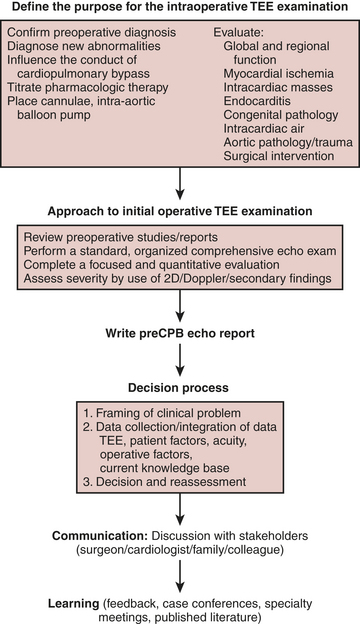
A formalized approach to the acquisition of data and decision-making (Fig. 10-3) enhances the quality of the intraoperative echocardiogram, its interpretation, and the confidence with which the findings are communicated to other members of the operative and nonoperative teams. The broad database that is required to formulate an intelligent decision includes provider- and patient-specific data. Patient-specific data include history and demographics, preoperative diagnostic examinations, admitting diagnosis and comorbidities, the patient’s wishes, recommendations of referring physicians, and intraoperative data. Intraoperative data include hemodynamic data, visual inspection, surgical input, and the TEE examination. A systematic TEE examination of the heart and great vessels permits the acquisition and interpretation of qualitative and quantitative echocardiographic data applied to intraoperative decision-making. The provider-specific data are composed of an accumulated database of knowledge acquired from training, experience, and continuous medical education.
INTRAOPERATIVE TRANSESOPHAGEAL ECHOCARDIOGRAPHY: INDICATIONS
The first decision by the echocardiographer is whether TEE is indicated. Application of intraoperative TEE in the care of the patient with mitral disease is widely accepted. Even in this area, however, there is a paucity of data supporting an improved outcome for intraoperative patients cared for with TEE compared with no TEE. The decision to perform TEE during cardiac surgery is substantiated by practice expectations and consensus opinion.5 In an attempt to develop an evidence-based approach to this expanding technology, the American Society of Anesthesiologists (ASA) and the Society of Cardiovascular Anesthesiologists (SCA) co-sponsored a task force to develop guidelines for defining the indications for perioperative TEE.2,6 Despite the scarcity of outcome data to support the application of TEE in the perioperative period, TEE had rapidly been adopted by cardiac surgeons and cardiac anesthesiologists as a routine monitoring and diagnostic modality during cardiac surgery. In 1996, the task force published their guidelines designed to establish the scientific merit of TEE and justification of its use in defined patient cohorts. The indications were grouped into three categories based on the strength of the supporting evidence/expert opinion that TEE improves outcome (Box 10-5). Category I indications suggested strong evidence/expert opinion that TEE was useful in improving clinical outcome. Category II indications suggested there was weak evidence/expert opinion that TEE improves outcome in these settings. Category III indications suggested there was little or no scientific merit or expert support for the application of TEE in these settings.
CASE STUDIES OF INTRAOPERATIVE TEE
Case Study 1
CARDIAC FUNCTION AND REGIONAL WALL MOTION ABNORMALITIES
DISCUSSION
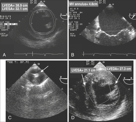
Preexisting ventricular dysfunction suggests increased risk for surgery and poorer long-term outcome. The presence of such ventricular dysfunction may deteriorate intraoperatively, requiring the need for marked pharmacologic or mechanical support. A patient with a preoperative EF of 10% scheduled for coronary artery bypass grafting (CABG) and MV repair is at increased risk of intraoperative ischemia, acute heart failure, and difficulty maintaining hemodynamic stability during the immediate postbypass period. Anticipating such problems, placement of an intra-aortic balloon pump or femoral arterial catheter is considered during the prebypass period (Fig. 10-4). The same patient is likely to benefit from the administration of inotropic agents.
Not all preexisting regional wall motion abnormalities benefit from coronary revascularization. Regions of akinesia and dyskinesia are usually the result of a myocardial infarction and may reflect nonviable myocardium, although “hibernating” myocardium is possible. Hypokinetic segments are generally viable and may represent active ischemia. Preoperative positron emission tomography (PET) scanning can detect hibernating myocardium and may be cost-effective to guide CABG.7 The detection of hibernating myocardium in an area of chronic ischemia and regional hypokinesis will direct the surgeon to revascularize the corresponding stenosed coronary artery. In contrast, an occluded coronary artery with downstream infarction may not benefit from revascularization, as contractile function may be irreversibly lost. However, in this latter scenario, revascularization postinfarction may provide some benefit in decreasing the risk of ventricular aneurysm formation.
If the intraoperative examination reveals new ventricular dysfunction, the intraoperative team must determine the etiology and severity and plan a treatment. Other causes of RWMAs such as conduction abnormalities (left bundle-branch block or ventricular pacing) can be difficult to distinguish. Treatment of myocardial ischemia may include optimizing hemodynamics; administering anticoagulants, nitrates, calcium channel blockers, or β-blockers; inserting an intra-aortic balloon pump; or instituting CPB and coronary revascularization. The presence of a new-onset RWMA after separation from bypass is worrisome for myocardial ischemia. Even the patient without coronary artery disease remains at risk because of hypotension, shower of air or debris into the coronary circulation, or coronary spasm. The patient with coronary artery disease undergoing coronary revascularization may have all the above risks, technical difficulties at the anastomotic site, injury to the native coronary (e.g., stitch caught the back wall), or occlusion of the coronary graft by thrombosis or aortic dissection. The coronary arteries, grafts, and anastomoses should be carefully inspected for patency and flow. Graft patency in the operating room is difficult to determine. Techniques include manual stripping and refill, measuring coronary flow by hand-held Doppler, or administration of echocardiographic contrast agents. A new RWMA in the distribution of a new coronary graft can prompt the decision-making strategies listed in Table 10-2.
Table 10-2 Management Strategies for New-Onset Myocardial Ischemia Post Bypass
| Diagnosis | Plausible Treatment |
|---|---|
| Coronary graft occlusion | Revise coronary graft |
| Coronary air emboli | Increase coronary perfusion pressure, administer coronary dilators |
| Coronary calcium/atheroma emboli | Support circulation |
| Dissection of the aortic root | Repair dissection |
| Coronary spasm | Administer coronary dilators |
Case Study 2
MANAGEMENT OF ISCHEMIC MITRAL REGURGITATION
FRAMING
Ischemic heart disease is the most common cause of mitral insufficiency in the United States. Mechanisms of valve incompetence are varied and include annular dilatation, papillary muscle dysfunction from active ischemia or infarction, papillary muscle rupture, or ventricular remodeling from scar, often leading to a tethering effect of the subvalvular apparatus. Mitral regurgitation leads to pulmonary hypertension, pulmonary vascular congestion, and pulmonary edema with functional disability. Ventricular function deteriorates as the LV becomes volume overloaded with corresponding chamber dilatation. Left untreated, severe MR from ischemic heart disease has a poor prognosis, hence the imperative for diagnosis and treatment.8 Patients presenting for surgical coronary revascularization often have concomitant MR of a mild or moderate degree. The intraoperative team is confronted with the decision of whether to surgically address the MV during the coronary operation.
DATA COLLECTION
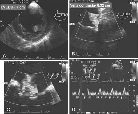
Pertinent data, including preoperative functional status and evaluation, need to be considered to appropriately interpret and place the intraoperative data in context. The preoperative echocardiogram and ventriculogram need to be reviewed. The intraoperative hemodynamic data are coupled with TEE information to complete the dataset needed to move forward with the decision-making process. The severity of MR on TEE is measured by the vena contracta, maximum area of the regurgitant jet, regurgitant orifice area, and pulmonary vein blood flow velocities. Wall motion assessment and the ECG are used for detecting reversible myocardial dysfunction that may benefit from revascularization. The hemodynamic and TEE data are coupled with provocative testing of the MV in an attempt to emulate the working conditions of the MV in an awake, unanesthetized state. It is not uncommon that preoperative mild to moderate MR with a structurally normal valve totally resolves under the unloading conditions of general anesthesia.9
DISCUSSION
The risks to the patient of not surgically altering the MV and anticipated residual regurgitation is weighed against the risk of atriotomy, mitral surgery, extending cardiopulmonary and aortic cross-clamp times, and the likelihood that the coronary surgery will be successful at decreasing the severity of MR. Added risk includes commitment to a mechanical prosthesis should a reparative procedure prove unsuccessful. MR due to acute ischemia may resolve after restoration of coronary blood flow (Fig. 10-5). The reversibility of the regurgitation is difficult to predict: factors supporting reversibility (and hence no immediate need to surgically address the valve) include a structurally normal MV, normal LA and LV dimension, including the mitral annulus, and RWMAs associated with transient regurgitation and pulmonary edema. Revascularization of the culprit myocardium with improvement in regional function may be all that is necessary to restore normal mitral coaptation.10 Myocardial infarction with a fixed wall motion defect or aneurysm, chronically dilated left-sided heart, dilated annulus, or other structural abnormalities that are not reversible (ruptured papillary muscle or chordae, leaflet prolapse, leaflet perforation) suggest myocardial revascularization is unlikely to correct the valvular incompetence.
Case Study 3
MANAGEMENT OF PREVIOUSLY UNDIAGNOSED AORTIC VALVE DISEASE
DATA COLLECTION AND CHARACTERIZATION OF THE AORTIC VALVE
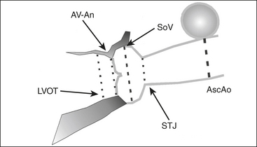
The etiology and extent of AV disease can be best delineated by TEE, as shown in Figure 10-6. The relatively high resolution of the AV and associated structures in the near field of the midesophageal short- and long-axis views permits an accurate assessment of the severity and mechanism of valvular disease. The aortic leaflets should be inspected in the midesophageal long-axis view for the presence of vegetations, perforation, restriction, thickening/calcification, malcoaptation, and leaflet prolapse. The presence of subvalvular disease, such as a discrete fibrous subaortic membrane, can also be reliably excluded. The ascending aorta from the valve to the right pulmonary artery also should be viewed in long axis. This view is usually optimal for examining associated pathology of the aortic root and ascending aorta (e.g., aortoannular ectasia, bicuspid valve, type A aortic dissection).
ASSESSMENT OF MILD AND MODERATE AORTIC STENOSIS
A review of 1,344,100 patients in the national database of the Society of Thoracic Surgeons having CABG, CABG/AVR, or AVR alone culminated in a decision paradigm recommendation. The study assumed rates of AV disease progression (pressure gradient of 5 mm Hg/yr), valve-related morbidity, and age-adjusted mortality rates that were obtained from published reports.11 The authors proposed three factors in the consideration of CABG or AVR/CABG: age (life expectancy), peak pressure gradient, and rate of progression of the AS (if known). Since the latter is difficult to discern, the analysis assumed an average rate of disease progression and recommended patients should undergo AVR/CABG when the pressure gradient exceeds 30 mm Hg. The threshold (AS pressure gradient) to perform both procedures is increased for patients older than 70 years of age because the reduced life expectancy diminishes the likelihood that they will become symptomatic from the AV disease. Whether to perform a concomitant AVR at the time of revascularization was also addressed by Rahimtoola, who advocated a less aggressive approach.12 One problem with both studies is that they analyzed the transvalvular pressure gradient, which may be a misleading measure of the degree of stenosis of the AV, as its value is dependent on CO. A low CO and flow rate will produce a low transvalvular pressure gradient, even in the setting of a severely stenotic AV. However, in the setting of preserved ventricular systolic function and mild or moderate AS, a pressure gradient is a useful metric. The variable rate of disease progression and the controversy regarding the indications for “prophylactic” AVR preclude a simple algorithm for dealing with this patient cohort. Increased age, lack of symptoms, minimal LV hypertrophy, with a valve area suggesting milder disease, and a pressure gradient less than 30 mm Hg would sway the decision to not replace the AV. In an asymptomatic young patient, a severely calcified valve, bicuspid valve, and LV hypertrophy in the setting of moderate stenosis, and a pressure gradient greater than 30 mm Hg would suggest that an AVR might be beneficial in the long term. It is often useful to include the patient’s primary cardiologist and family in the decision-making process.
ASSESSMENT OF LOW PRESSURE GRADIENT AORTIC STENOSIS
Patients with LV dysfunction and decreased CO in the setting of AS often present with only modest transvalvular pressure gradients (<30 mm Hg). Distinguishing patients with a low CO and severe AS from patients with mild to moderate AS can be challenging (Fig. 10-7). The standard for assessing severity of AS is AV area, typically calculated using either a continuity method or by planimetry. Patients with low-gradient AS with severe LV dysfunction who received an AVR had improved survival and functional status compared with patients who did not have a valve replacement.13
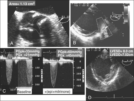
A low pressure gradient related to LV dysfunction may not open the AV to its maximum capacity. Dobutamine challenge in a patient with low pressure gradient AS can be useful in establishing true AV area. The ability to distinguish between true AV stenosis and a state of “pseudostenosis” relies on characteristic changes in hemodynamic and structural measurements in response to the augmented CO. The test is not typically performed in the operative setting but rather as a preoperative evaluation. The increase in calculated AV area is related to the increase in the CO and is attributed to partial reversal of primary cardiac dysfunction. If dobutamine improves CO and increases AV area, it is likely the baseline calculations overestimated the severity of the AS. The dobutamine challenge is conducted as follows: patients with low-gradient AS receive intravenous dobutamine at 5 μg/kg/min with stepwise increases in dose. Patients may exhibit a significant increase in AV area (0.8 cm2 to 1.1 cm2) and a decline in valve resistance after dobutamine challenge. Patients with fixed, high-grade AS would demonstrate no change in valve area and an increase in valve resistance. The 2003 ACC/AHA/ASE Task Force gave a class IIb recommendation (usefulness/efficacy is less well established by evidence/opinion) for the use of dobutamine echocardiography in the evaluation of patients with low-gradient AS and ventricular dysfunction.14 In addition to its role in distinguishing between true stenosis and pseudostenosis, low-dose dobutamine echocardiography is helpful in risk stratifying of patients with severe true AS. Patients with augmented contractile function after dobutamine administration have an improved outcome after surgery.15
Case Study 4
ACUTE AORTIC SYNDROMES
FRAMING
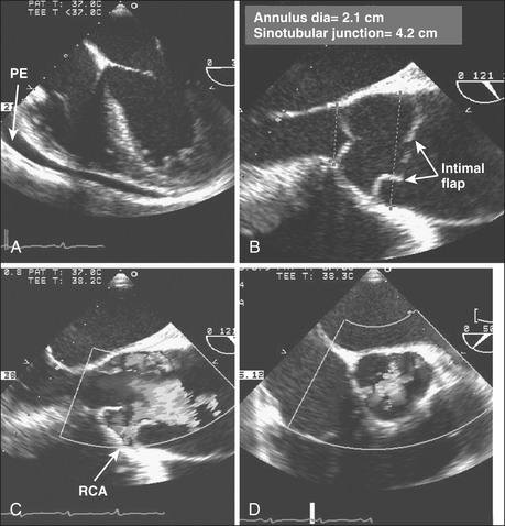
It is midnight on a gloomy rainy night. The hospital helicopter pilot calls in “young woman, unrestrained driver, deceleration injury, steering wheel impact, chest contusion, unconscious, hypotensive. She is intubated with bilateral breath sounds. Her blood pressure is 70/40 mm Hg with an HR = 125 sinus tachycardia. She is being fluid resuscitated and being transported directly to the cardiac operating room.” The patient is too unstable for magnetic resonance imaging (MRI) or computed tomography (CT). The patient arrives with a portable chest radiograph obtained as she traveled through the emergency department, showing a widened mediastinum. The vital signs have not changed except that she is receiving dopamine at 10 μg/kg/min. Pulses are palpable in the groins and the neck (Fig. 10-8). The attending surgeon turns to the echocardiographer-anesthesiologist and asks, “I need to know whether this is an anterior injury with heart contusion, injury to the ascending aorta, tamponade with blood in the pericardium, or a transected aorta or does the patient have a nonoperable injury? The former will require a sternotomy. The transections will require a left thoracotomy. If we make the incorrect decision, the patient will surely die.” The patient is stabilized in the operating room and the TEE probe is inserted. After the diagnosis is made, the patient is positioned and prepped accordingly for the definitive surgery.
The sensitivity and specificity of TEE to detect and diagnose injury or disease of the thoracic aorta are significantly better than the sensitivity and specificity of TTE and are comparable to findings on CT and MRI.16 TEE provides information regarding cardiac performance and the presence of other critically important sequelae that may be important in determining the approach and timing for surgical intervention. Hence, TEE is indicated even if MRI or CT has confirmed the diagnosis.
DISCUSSION
Acute dissections (Stanford type A or DeBakey type I or type II) involving the ascending aorta or arch are considered acute surgical emergencies. In contrast, dissections confined to the descending aorta (distal to the left subclavian artery; Stanford type B or DeBakey type III) are treated medically unless the patient demonstrates proximal extension, hemorrhage, or malperfusion. From the International Registry of Acute Aortic Dissection (IRAD), 73% of the 384 patients with type B dissections were managed medically; in-hospital mortality was 10%.17 The long-term survival rate after applying medical therapy is 60% to 80% at 4 to 5 years and 40% to 45% at 10 years. Survival is best in patients with noncommunicating and retrograde dissections. From the IRAD registry, in-hospital mortality for surgical patients was significantly higher (32%). The increased rate of mortality for surgically treated patients is likely influenced by selecting a cohort of patients with more advanced disease and complicated course (malperfusion, leakage, extension). The overall reported short- and long-term outcomes are similar for medically treated patients with type B dissections. Of 142 patients with type aortic dissections, there was a trend toward lower mortality with medical therapy compared with surgical treatment at 1 year (15% vs. 33%). Both groups had similar survival at 5 and 10 years (60% and 35%).
Ascending aortic dissections (involving the aortic root, ascending aorta, or arch) are acute surgical emergencies, because of the high risk for a life-threatening complication such as AR, cardiac tamponade, myocardial infarction, rupture, and stroke. The mortality rate is as high as 1% to 2% per hour early after symptom onset. Neither acute myocardial ischemia nor cerebral infarction should contraindicate urgent intervention. Although patients with stroke in progress may be at increased risk for hemorrhagic cerebral infarction due to intraoperative anticoagulation, leading to hemorrhagic stroke, the authors have seen several patients who experienced dramatic neurologic recovery. Operative mortality for ascending aortic dissections at experienced centers varies from 7% to 36%, well below the greater than 50% mortality with medical therapy.18
Traumatic aortic rupture is a life-threatening vascular injury that often results in lethal hemorrhage. In a multicenter trial of 274 patients, the overall mortality rate reached 31%, with 63% of deaths attributable to aortic rupture. Aortic transection and rupture usually occur at the aortic isthmus (between the left subclavian and the first intercostal arteries) and result from shear forces generated by unrestrained frontal collisions. Although aortography had been considered the gold standard for the diagnosis of transection, TEE and contrast-enhanced spiral CT and MRI are currently favored, especially for patients with renal insufficiency.19 Intravascular ultrasonography has been proposed as a potential diagnostic tool for the identification of limited aortic injuries. Traumatic aortic rupture needs to be distinguished from an aortic dissection. Imaging of a dissected aorta typically reveals true and false lumens at multiple levels. The focal aortic injury of aortic transection is quite localized and may be overlooked when performing a cursory examination. A second potential diagnostic problem is that protuberant atherosclerotic changes of the aorta may be difficult to differentiate from partial aortic tears. The thick and irregular intraluminal flap, which corresponds to disruption of both intimal and medial aortic layers, can be imaged in both the short- and long-axis planes in the vicinity of the isthmus. In the longitudinal view, the medial flap is nearly perpendicular to the aortic wall because traumatic lesions are usually confined within a few centimeters distal to the left subclavian. The formation of a localized contained rupture of the false aneurysm is common. Color flow Doppler imaging and spectral Doppler imaging can be used to detect turbulence associated with nonlaminar flow at the aortic defect and the presence of a pressure gradient. Traditional treatment includes immediate surgical intervention using a right lateral decubitus approach and resection of the aorta with insertion of a tube graft. Deployment of endovascular stent grafts has been successful. Two series that included a total of 16 patients having aortic transection reported successful repair with no mortality or serious morbidity.20 However, the application of this device under such conditions poses a high risk for left subclavian malperfusion and paraplegia. The decision regarding appropriate management and time course of therapy will depend on the technical availability and expertise within the institution and the forthcoming results of clinical trials that use newer, less invasive technologies.
SUMMARY
1. Miller A.P., Nanda N.C. Contrast echocardiography: New agents. Ultrasound Med Biol. 2004;30:425.
2. Shanewise J., Cheung A., Aronson S., et al. ASE/SCA guidelines for performing a comprehensive intraoperative multiplane transesophageal echocardiography examination: Recommendations of the American Society of Echocardiography Council for Intraoperative Echocardiography and the Society of Cardiovascular Anesthesiologists Task Force for Certification in Perioperative Transesophageal Echocardiography. Anesth Analg. 1999;89:870.
3. Weyman A.F. The year in echocardiography. J Am Coll Cardiol. 2005;45:48.
4. Fleisher L., Welskopf R. Real-time intraoperative monitoring of myocardial ischemia in noncardiac surgery. Anesthesiology. 2000;92:1183.
5. Kallmeyer I.J., Collard C.D., Fox J.A., et al. The safety of intraoperative transesophageal echocardiography: A case series of 7200 cardiac surgical patients. Anesth Analg. 2001;92:1126.
6. Practice guidelines for perioperative transesophageal echocardiography. A report by the American Society of Anesthesiologists and the Society of Cardiovascular Anesthesiologists Task Force on Transesophageal Echocardiography. Anesthesiology. 1996;84:986.
7. Kozman H., Cook J.R., Wiseman A.H., et al. Presence of angiographic coronary collaterals predicts myocardial recovery after coronary bypass surgery in patients with severe left ventricular dysfunction. Circulation. 1998;98:II-57.
8. Grigioni F., Enriquez-Sarano M., Zehr K.J., et al. Ischemic mitral regurgitation: Long-term outcome and prognostic implications with quantitative Doppler assessment. Circulation. 2001;103:1759.
9. Grewal K.S., Malkowski M.J., Piracha A.R., et al. Effect of general anesthesia on the severity of mitral regurgitation by transesophageal echocardiography. Am J Cardiol. 2000;85:199.
10. Guy T.S., Moainie S.L., Gorman J.H.III, et al. Prevention of ischemic mitral regurgitation does not influence the outcome of remodeling after posterolateral myocardial infarction. J Am Coll Cardiol. 2004;43:377.
11. Smith W.T., Ferguson T.B.Jr., Ryan T., et al. Should coronary artery bypass graft surgery patients with mild or moderate aortic stenosis undergo concomitant aortic valve replacement? A decision analysis approach to the surgical dilemma. J Am Coll Cardiol. 2004;44:1241.
12. Rahimtoola S.H. “Prophylactic” valve replacement for mild aortic valve disease at time of surgery for other cardiovascular disease? No. J Am Coll Cardiol. 1999;33:2009.
13. Pereira J.J., Lauer M.S., Bashir M., et al. Survival after aortic valve replacement for severe aortic stenosis with low transvalvular gradients and severe left ventricular dysfunction. J Am Coll Cardiol. 2002;39:1356.
14. Cheitlin M.D., Armstrong W.F., Aurigemma G.P., et al. ACC/AHA/ASE 2003 guideline update for the clinical application of echocardiography—summary article: A report of the American College of Cardiology/American Heart Association Task Force on Practice Guidelines (ACC/AHA/ASE Committee to Update the 1997 Guidelines for the Clinical Application of Echocardiography). J Am Coll Cardiol. 2003;42:954.
15. Monin J.L., Quere J.P., Monchi M., et al. Low-gradient aortic stenosis: Operative risk stratification and predictors for long-term outcome: A multicenter study using dobutamine stress hemodynamics. Circulation. 2003;108:319.
16. Feindel C.M., David T.E. Aortic valve sparing operations: Basic concepts. Int J Cardiol. 2004;97:61.
17. Suzuki T., Mehta R.H., Ince H., et al. Clinical profiles and outcomes of acute type B aortic dissection in the current era: Lessons from the International Registry of Aortic Dissection (IRAD). Circulation. 2003;108(Suppl II):II-312.
18. Nienaber C.A., Eagle K.A. Aortic dissection: New frontiers in diagnosis and management: I. From etiology to diagnostic strategies. Circulation. 2003;108:628.
19. Goarin J.P., Cluzel P., Gosgnach M., et al. Evaluation of transesophageal echocardiography for diagnosis of traumatic aortic injury. Anesthesiology. 2000;93:1373.
20. Ott M.C., Stewart T.C., Lawlor D.K., et al. Management of blunt thoracic aortic injuries: Endovascular stents versus open repair. J Trauma. 2004;56:565.
[/level-membership-for-anesthesiology-category][not-level-membership-for-anesthesiology-category]
Chapter 10 Intraoperative Echocardiography
Few areas in cardiac anesthesia have developed as rapidly as the field of intraoperative echocardiography. In the early 1980s, when transesophageal echocardiography (TEE) was first used in the operating room, its main application was the assessment of global and regional left ventricular (LV) function. Since that time there have been numerous technical advances: biplane and multiplane probes; multifrequency probes; enhanced scanning resolution; color flow, pulsed wave, and continuous wave Doppler; automatic edge detection; Doppler tissue imaging; three-dimensional (3D) reconstruction; and digital image processing. With these advances, the number of clinical applications of TEE has markedly increased. The common applications of TEE include (1) assessment of valvular anatomy and function, (2) evaluation of the thoracic aorta, (3) detection of intracardiac defects, (4) detection of intracardiac masses, (5) evaluation of pericardial effusions, (6) detection of intracardiac air and clots, and (7) assessment of biventricular systolic and diastolic function. In many of these evaluations, TEE is able to provide unique and critical information that was not previously available in the operating room (Box 10-1).
BASIC CONCEPTS
Imaging Techniques
Contrast Echocardiography
Contrast echocardiography has been used to image intracardiac shunts, valvular incompetence, and pericardial effusions. In addition, LV injections of hand-agitated microbubble solutions have been used to identify semiquantitative LV endocardial edges, cardiac output, and valvular regurgitation (Box 10-2).
Contrast agents are microbubbles, consisting of a shell surrounding a gas. Initial contrast agents were agitated free air in either a saline or blood/saline solution. These microbubbles were large and unstable, so they were unable to cross the pulmonary circulation; they were effective only for right-sided heart contrast. Because of their thin shell, the gas quickly leaked into the blood with resultant dissolution of the microbubble. Agents with a longer persistence were subsequently developed.1
COMPLICATIONS
Complications resulting from intraoperative TEE can be separated into two groups: injury from direct trauma to the airway and esophagus and indirect effects of TEE (Box 10-3). In the first group, potential complications include esophageal bleeding, burning, tearing, dysphagia, and laryngeal discomfort. Many of these complications could result from pressure exerted by the tip of the probe on the esophagus and the airway. Although in most patients even maximal flexion of the probe will not result in pressure above 17 mm Hg, occasionally, even in the absence of esophageal disease, pressures greater than 60 mm Hg will result.
ANATOMY AND TRANSESOPHAGEAL ECHOCARDIOGRAPHY VIEWS
Multiplane Transesophageal Echocardiography Probe Manipulation: Descriptive Terms and Technique
The process of obtaining a comprehensive intraoperative multiplane TEE examination begins with a fundamental understanding of the terminology and technique for probe manipulation (Fig. 10-1).2 Efficient probe manipulation minimizes esophageal injury and facilitates the process of acquiring and sweeping through 2D image planes. Horizontal imaging planes are obtained by moving the TEE probe up and down (proximal and distal) in the esophagus at various depths relative to the incisors (upper esophageal: 20 to 25 cm; midesophageal: 30 to 40 cm; transgastric: 40 to 45 cm; deep transgastric: 45 to 50 cm) (Table 10-1). Vertical planes are obtained by manually turning the probe to the patient’s left or right. Further alignment of the imaging plane can be obtained by manually rotating one of the two control wheels on the probe handle, which flexes the probe tip to the left or right direction or in the anterior or posterior plane. Multiplane probes may further facilitate interrogation of complex anatomic structures, such as the mitral valve (MV), by allowing up to 180 degrees of axial rotation of the imaging plane without manual probe manipulation.
Table 10-1 The Comprehensive Intraoperative Multiplane Transesophageal Echocardiographic Examination
| Probe Tip Depth (from lips): Upper Esophageal (20 to 25 cm) | |
| View | Aortic arch: long axis |
| Multiplane angle range | 0° |
| Anatomy imaged | Aortic arch; left brachiocephalic vein; left subclavian and carotid arteries; right brachiocephalic artery |
| Clinical utility | |
The Comprehensive Intraoperative Transesophageal Echocardiography Examination: Imaging Planes and Structural Analysis
Left and Right Ventricles
The LV should be carefully examined for global and regional function using multiple transducer planes, depths, and rotational and angular orientations (Fig. 10-2
[/not-level-membership-for-anesthesiology-category]
