[level-membership-for-neurosurgery-category]
Chapter 47 Interspinous, Laminar, and Facet Fusion
Basic to the details of therapeutic intervention, either operative or nonoperative, is an understanding of the biomechanical principles of cervical spine function. These considerations permit the most effective planning of a specific treatment, especially the details of surgical intervention. Generally, in the cervical region, the major mechanism of injury is transmission of force through the head. The corresponding changes are usually related to flexion, extension, or rotation, with associated axial compression or distraction. Clarification of these factors assists the surgeon in designing the most appropriate procedure. A surgeon therefore desires to counteract the major force vectors responsible for the principal injury pattern. (One would not accentuate an extension-compression or extension-distraction injury by increasing extension forces with certain posterior fixation procedures.) The selected method of treatment should be based on the biomechanics of the injury and the experience and preference of the surgeon. This chapter covers the factors predisposing to instability in the subaxial (C3-7) cervical spine and the management of instability, using wire and cable techniques. Allen et al.1 proposed a mechanistic classification based on biomechanical considerations of the injury vectors. Panjabi and White2 proposed a working classification, especially for acute instability, in which more than 3.5 mm of anterolisthesis or more than 11 degrees of angulation constitutes instability in the lower cervical spine; this classification may be helpful in evaluation. In awake patients who fail to demonstrate radiologic evidence of instability with routine cervical spine films, flexion-extension lateral radiographs should be obtained. Dynamic radiographs, however, should be approached with a level of caution. The situation is often best approached initially by CT, with sagittal reconstruction for full definition of the possible injury patterns. If instability is not demonstrated with the aforementioned studies yet is suspected from the increased prevertebral soft tissue swelling and the severe neck pain, these patients should be placed in a firm cervical collar and the flexion-extension films repeated in 2 weeks. The elapsed time allows muscle spasm to abate and allows demonstration of ligamentous instability on the flexion-extension radiographs.
Initial Management
Muscle relaxation with agents such as diazepam (Valium) assists reduction of the subluxation and alignment of the spine. Weights are added in 5-lb increments to a maximum of 35 to 40 lbs. Lateral cervical spine radiographs are obtained after each weight or position change to monitor cervical spine alignment. Patients with injuries that do not reduce on graded cervical traction, as well as those who cannot tolerate traction, are considered for early surgical reduction and stabilization. All patients with spinal cord injury with moderate to severe neurologic deficit are started on the Solu-Medrol protocol.3
Timing of Surgery
Surgery for cervical spine instability may be performed ultra early (in <6–8 hours), early (in 24–72 hours), or late (several days to weeks later). The temporal course of events may be conditioned by the presence of other associated injuries, but generally most surgeons operate on these patients between 24 and 72 hours, unless during this period there is deterioration of the patient’s neurologic status since admission. Deterioration of the neurologic status may suggest corresponding vertebral artery compromise or other events that may indicate consideration for emergent surgery. In patients with partial neurologic injury and nonreduction of the subluxation, the ongoing bony or soft tissue compression may suggest a theoretical advantage to early surgery in reducing secondary neurologic injury; the full validity of this concept has not been fully defined, however.4 In neurologically intact patients and patients with a complete neurologic deficit noted from the outset, timing is not as critical. However, early mobilization should minimize pulmonary and other complications.
Operative Techniques
Positioning, Intubation, and Monitoring
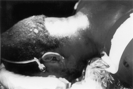
The patient is turned to the prone position, in a firm cervical collar with manual traction applied to the head ring by the surgeon. The head is supported in a cerebellar head rest, and traction is reestablished (Fig. 47-1). Mayfield skull clamps can be used if alignment can be maintained without traction. The latter mode of fixation minimizes problems with pressure necrosis of the face and potentially disastrous ocular injury. A lateral cervical spine radiograph is obtained to check alignment after turning and positioning the patient.
Exposure
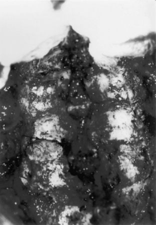
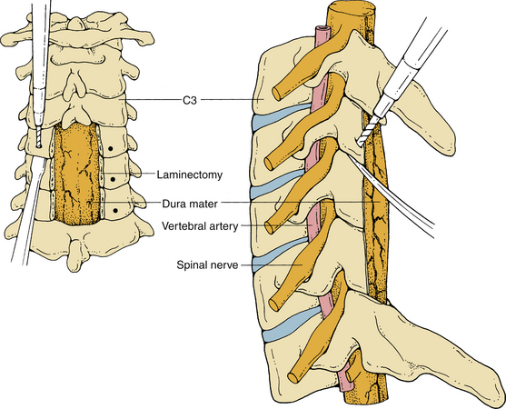
Reduction of preoperatively unreduced, unilateral, or bilateral locked (“jumped”) facets should be attempted at this time. The tip of the superior facet is drilled. Using two straight curettes between the adjacent laminae in the “tire-lever” B-type maneuver and working from medially to laterally toward the facet joint, the surgeon removes the superior facet ventral to the inferior facet (Fig. 47-2). In cases in which there is a facet fracture with encroachment into the neural foramen, this fragment of bone should be removed to relieve pressure on the exiting nerve root. The surgeon should always be aware of the potential for a lateral mass fracture that mimics a unilateral facet displacement.
Wire and Cable Fixation
The dorsal anatomic configuration of the subaxial cervical spine favors the use of adjunctive wire and cable fixation techniques. Wire and cable can be passed through and around spinous processes, through facet joints, and underneath the laminae. Sublaminar passage of wire in the subaxial spine may injure the spinal cord. Thus most surgeons restrict the use of sublaminar cables and wires to the more capacious upper cervical spine only, avoiding the regions of cervical spinal cord enlargement. These wires and cables can also be used to hold the bone graft to the spine, laminae, and facets.
Interspinous Wiring
The majority of patients with cervical spine instability can be treated with wiring. Since Rogers first reported a high success rate for cervical fusion with a single, interspinous wiring, numerous techniques of dorsal wiring have been defined. As previously noted, the availability of commercially prepared, braided-wire (cable) systems has improved the technical ease of applying some of these wiring methods. Basically the systems are 18 gauge (Songer) and 20 gauge (Codman), with varying characteristics that may offer improved usage in different constructs. Each system is available in stainless steel or titanium, with specific force application limits that are dependent on the specific type of metal. The braided character of the cables markedly improves strength and malleability. These characteristics are not meant to imply a universal acceptance of the cable systems in creating dorsal constructs; some surgeons prefer the less malleable Luque wire, especially when applying compression techniques with spinous process wiring.5
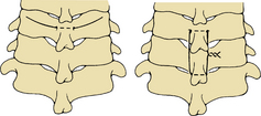
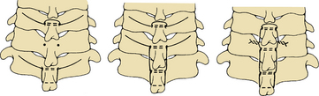
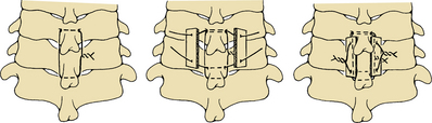
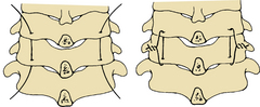
After exposure of the appropriate levels in the cervical spine and confirmation by radiography, the process of wiring can begin. For spinous process wiring, a transverse hole is made at the junction of the spinous process and lamina of the most rostral level to be fused. This can be made using a power drill and can be completed with a large towel clip. Care should be taken not to angle the drill ventrally and enter the spinal canal. The use of a right-angled dental drill appliance permits a straight lateral drill path. The leader wire of the cable system is passed through the drill hole at the spinolaminar junction and then carried distally, parallel across the interspace, down to the next most rostral spinous process. The cable ends are then passed in opposite directions around the caudal aspect of that spinous process (Fig. 47-3A and B). The cable is tightened with the Tensioner-Crimper, as defined by the recommendations of the system’s manufacturer. The wire can also be looped around the rostral border of the spinolaminar junction of the upper level and then threaded in opposite directions through the drill hole at the spinolaminar junction, before being carried caudally.6 Alternatively, the cable can be passed in the form of a loop through two drill holes at the base of the two spinous processes to be fused. In multilevel fusion each level is wired individually, beginning at the rostral end (Fig. 47-4). This latter construct places the majority of the stress between the donor bone and wire, rather than between the spinous process and wire.
With dorsal cervical interspinous compression wiring in the subaxial spine,7 the base of the most rostral spinous process to be fused is cannulated. Double-stranded, 22-gauge, stainless-steel wire is passed through the hole in the upper spinous process and around the base of the lower spinous process. A single-stranded, 22-gauge wire (compression wire) is placed between the two spinous processes and underneath the twisted wire. Then it is used to secure the bone graft to the spinous processes. The two ends of the double-stranded cerclage wire are twisted together to achieve the required alignment of the cervical spine (Fig. 47-5).

Triple-Wire Technique
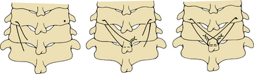
Three wires are used in the triple-wire technique.8 A drill hole is made at the spinolaminar junction, as described previously. Both levels to be fused have drill holes made at the spinolaminar junction. A single-stranded, 20-gauge wire is looped around the rostral border of the rostral process and then passed from opposite directions through the drill hole in that process. The wires are then passed caudally, parallel across the interspace down to the drill hole in the lower process. One end of the wire is passed through the drill hole at the caudal process and then looped around the base of the spinous process at that level, before coming back through the same drill hole. It is torqued to the opposite end of the wire that is emerging from the rostral drill hole (Fig. 47-6). This wiring arrangement is described as the tethering wire. Two separate 22-gauge wires are passed from either side through the same holes to secure the bone graft. After decortication, the two corticocancellous strips of bone are wired down snugly. Biomechanical studies have verified the strength of this construct, and case reviews have described excellent union with this technique.8
Oblique Wiring
Most wiring techniques are effective in restricting flexion, but are less effective in limiting extension and especially rotation. Modification of wire fixation has been developed to aid in the treatment of rotational instability, especially as encountered with facet dislocation.9 A standard dorsal midline incision is made in the neck, with the patient in the prone position. The segments to be fused are exposed, with care taken not to take down the supraspinous, interspinous, and capsular ligaments. After the segmental level is confirmed with lateral cervical radiographs, the facet joint capsule at the level to be fused is taken down. If the facet dislocation is not reduced, this can be achieved manually, as described in the previous section. A small, angled curette is used to remove articular cartilage from within the facet joint to be fused. The facet joint is opened using a Penfield, or periosteal, elevator, which is also used to protect the superior facet below during drilling. To open the facet joint and ease the wire passage, it is advisable to bur down the superior facet. Often the frustration of passing a facet wire is caused by the lack of a widely opened facet joint. A 3⁄32-inch drill, or bur, is used to make the hole in the inferior facet (Fig. 47-7). The drill hole is made at the center of the inferior facet, angled slightly medially and caudally. A 22-gauge braided wire or cable is passed through the drill hole, with the facet joint kept open by the Penfield dissector. The end of the wire, or “leader,” of the cable is picked up within the joint with a curved hemostat. By a combination of pushing and feeding the wire from above, together with pulling from below, the wire is threaded. Vigorous pulling and pushing will produce a “Gigli saw” effect and cut through the inferior facet. The upper limb of the wire is passed through the interspinous ligament above the spinous process to be wired, and the lower limb of the wire is passed through the interspinous ligament below the spinous process to be wired (Fig. 47-8). The wire is twisted, or the cable is torqued and crimped on the opposite side of the lower spinous process. The application, in a bilateral fashion, establishes both flexion and rotational stability.
Facet Wiring
The facet joints are major determinants of cervical motion. Numerous studies have demonstrated that facet joint instability occurs with both dorsal ligamentous and dorsal bony injuries.10–12 Functional unit studies have shown approximately a 30% decrease in stiffness to flexion-compression load with unilateral facetectomy and approximately a 50% decrease in stiffness with bilateral facetectomies. Facet-to-facet or facet-to-spinous process fixation resulted in significant restoration to intact levels but demonstrated persistent interspinous motion.10 This latter finding suggests that facet wiring techniques should be associated with spinous process wiring, if available. Other in vitro studies have verified the relative contribution of the facet joint to stability and the merits of fixation.11,12
The technique of wire placement is similar to oblique wiring. Again, the wide opening formed in the facet joint by drilling down the upper portion of the superior facet assists wire or cable passage. A bicortical, biconcave bone graft is laid over the decorticated facets to be fused, and the two limbs of the facet wires are brought around the bone graft and twisted (Fig. 47-9).13 This construct, however, may not provide adequate stiffening and is best considered primarily a method to secure the graft to the facets. A similar technique may also be used to wire down contoured rods and Luque rectangles, especially in postlaminectomy patients. This latter form of stabilization will significantly decrease flexibility, offering a firmer construct with improved expectations for resistance to flexion, extension, and rotation.14
Fusion
The dorsal elements of the subaxial spine to be fused are decorticated with a cutting bur. Roughening of the bone is usually sufficient in the cervical spine to assist onlay bone fusion. The facet joint to be fused is denuded of capsule, and a small, curved curette is used to remove the joint cartilage and roughen the opposing surfaces of the facet joint. Cancellous bone graft is interposed into the facet joint before the wire or cable is tightened. Further bone graft is laid around the wires over the decorticated spines and laminae. In the technique of facet wiring, bicortical bone graft, contoured in two planes, is laid over the decorticated lateral masses and facets to be fused and wired.
Benzel E.C., Kesterson L. Posterior cervical interspinous compression wiring and fusion for mid to low cervical spinal injuries. J Neurosurg. 1989;70:893-899.
Cooper P.R., Cohen A., Rosiello A., Koslow M. Posterior stabilization of cervical spine fractures and subluxations using plates and screws. Neurosurgery. 1988;23:300-306.
Cusick J.F., Yoganandan N., Pintar F.A., Hussain H. Biomechanics of cervical spine facetectomy and fixation techniques. Spine (Phila Pa 1976). 1988;13:808-812.
McAfee P.C., Bohlman H.H., Wilson W.L. Triple wire technique for stabilization of acute cervical fracture dislocations. Orthop Trans. 1986;10:455-456.
Zdeblick T.A., Zau D.D., Warden K.E., et al. Cervical stability after foraminotomy. J Bone Joint Surg [Am]. 1992;74:22-29.
1. Allen B.L., Ferguson R.L., Lehman T.R., et al. A mechanistic classification of closed, indirect fractures and dislocations of the lower cervical spine. Spine (Phila Pa 1976). 1982;7:1-27.
2. White A.A., Panjabi M. The role of stabilization in the treatment of cervical spine injuries. Spine (Phila Pa 1976). 1984;9:512-522.
3. Bracken M.B., Shepard M.J., Collins W.F., et al. A randomized controlled trial of methylprednisolone or naloxone in the treatment of acute spinal cord injury: results of the 2nd National Acute Spinal Cord Injury Study. N Engl J Med. 1990;322:1405-1411.
4. Ducker T.B., Bellegarringue R., Scallion M., et al. Timing of operative care in cervical spinal cord injury. Spine (Phila Pa 1976). 1984;9:525-531.
5. Alexander E. Decompression and fixation in cervical spine fractures: indications and techniques. Clin Neurosurg. 1980;27:401-413.
6. Rogers W.A. Treatment of fracture dislocations of the cervical spine. J Bone Joint Surg. 1942;24:245-258.
7. Benzel E.C., Kesterson L. Posterior cervical interspinous compression wiring and fusion for mid to low cervical spinal injuries. J Neurosurg. 1989;70:893-899.
8. McAfee P.C., Bohlman H.H., Wilson W.L. Triple wire technique for stabilization of acute cervical fracture dislocations. Orthop Trans. 1986;10:455-456.
9. Cahill D.W. Bellegarringue R, Ducker TB: Bilateral facet to spinous process fusion: a new technique for posterior spinal fusion after trauma. Neurosurgery. 1983;13:1-4.
10. Cusick J.F., Yoganandan N., Pintar F.A., Hussain H. Biomechanics of cervical spine facetectomy and fixation techniques. Spine (Phila Pa 1976). 1988;13:808-812.
11. Goel V.K., Clark C.R., Harris K.G., Schulte K.R. Kinematics of the cervical spine: effects of multiple total laminectomy and facet wiring. J Orthop Res. 1988;6:611-619.
12. Zdeblick T.A., Zau D.D., Warden K.E., et al. Cervical stability after foraminotomy. J Bone Joint Surg [Am]. 1992;74:22-29.
13. Callahan R.A., Johnson R.M., Margolis R.H., et al. Cervical facet fusion for control of instability following laminectomy. J Bone Joint Surg [Am]. 1977;59:991-1002.
14. Cooper P.R., Cohen A., Rosiello A., Koslow M. Posterior stabilization of cervical spine fractures and subluxations using plates and screws. Neurosurgery. 1988;23:300-306.
[/level-membership-for-neurosurgery-category][not-level-membership-for-neurosurgery-category]
Chapter 47 Interspinous, Laminar, and Facet Fusion
Basic to the details of therapeutic intervention, either operative or nonoperative, is an understanding of the biomechanical principles of cervical spine function. These considerations permit the most effective planning of a specific treatment, especially the details of surgical intervention. Generally, in the cervical region, the major mechanism of injury is transmission of force through the head. The corresponding changes are usually related to flexion, extension, or rotation, with associated axial compression or distraction. Clarification of these factors assists the surgeon in designing the most appropriate procedure. A surgeon therefore desires to counteract the major force vectors responsible for the principal injury pattern. (One would not accentuate an extension-compression or extension-distraction injury by increasing extension forces with certain posterior fixation procedures.) The selected method of treatment should be based on the biomechanics of the injury and the experience and preference of the surgeon. This chapter covers the factors predisposing to instability in the subaxial (C3-7) cervical spine and the management of instability, using wire and cable techniques. Allen et al.1 proposed a mechanistic classification based on biomechanical considerations of the injury vectors. Panjabi and White2 proposed a working classification, especially for acute instability, in which more than 3.5 mm of anterolisthesis or more than 11 degrees of angulation constitutes instability in the lower cervical spine; this classification may be helpful in evaluation. In awake patients who fail to demonstrate radiologic evidence of instability with routine cervical spine films, flexion-extension lateral radiographs should be obtained. Dynamic radiographs, however, should be approached with a level of caution. The situation is often best approached initially by CT, with sagittal reconstruction for full definition of the possible injury patterns. If instability is not demonstrated with the aforementioned studies yet is suspected from the increased prevertebral soft tissue swelling and the severe neck pain, these patients should be placed in a firm cervical collar and the flexion-extension films repeated in 2 weeks. The elapsed time allows muscle spasm to abate and allows demonstration of ligamentous instability on the flexion-extension radiographs.
Initial Management
Muscle relaxation with agents such as diazepam (Valium) assists reduction of the subluxation and alignment of the spine. Weights are added in 5-lb increments to a maximum of 35 to 40 lbs. Lateral cervical spine radiographs are obtained after each weight or position change to monitor cervical spine alignment. Patients with injuries that do not reduce on graded cervical traction, as well as those who cannot tolerate traction, are considered for early surgical reduction and stabilization. All patients with spinal cord injury with moderate to severe neurologic deficit are started on the Solu-Medrol protocol.3
Timing of Surgery
Surgery for cervical spine instability may be performed ultra early (in <6–8 hours), early (in 24–72 hours), or late (several days to weeks later). The temporal course of events may be conditioned by the presence of other associated injuries, but generally most surgeons operate on these patients between 24 and 72 hours, unless during this period there is deterioration of the patient’s neurologic status since admission. Deterioration of the neurologic status may suggest corresponding vertebral artery compromise or other events that may indicate consideration for emergent surgery. In patients with partial neurologic injury and nonreduction of the subluxation, the ongoing bony or soft tissue compression may suggest a theoretical advantage to early surgery in reducing secondary neurologic injury; the full validity of this concept has not been fully defined, however.4 In neurologically intact patients and patients with a complete neurologic deficit noted from the outset, timing is not as critical. However, early mobilization should minimize pulmonary and other complications.
Operative Techniques
Positioning, Intubation, and Monitoring
The patient is turned to the prone position, in a firm cervical collar with manual traction applied to the head ring by the surgeon. The head is supported in a cerebellar head rest, and traction is reestablished (Fig. 47-1). Mayfield skull clamps can be used if alignment can be maintained without traction. The latter mode of fixation minimizes problems with pressure necrosis of the face and potentially disastrous ocular injury. A lateral cervical spine radiograph is obtained to check alignment after turning and positioning the patient.
Exposure
Reduction of preoperatively unreduced, unilateral, or bilateral locked (“jumped”) facets should be attempted at this time. The tip of the superior facet is drilled. Using two straight curettes between the adjacent laminae in the “tire-lever” B-type maneuver and working from medially to laterally toward the facet joint, the surgeon removes the superior facet ventral to the inferior facet (Fig. 47-2). In cases in which there is a facet fracture with encroachment into the neural foramen, this fragment of bone should be removed to relieve pressure on the exiting nerve root. The surgeon should always be aware of the potential for a lateral mass fracture that mimics a unilateral facet displacement.
