Chapter 48 Interference Screw Fixation in Bone–Patellar Tendon–Bone Anterior Cruciate Ligament Reconstruction
Introduction
Interference screw fixation on both the femoral and tibial sides remains an effective fixation scheme for bone–patellar tendon–bone (BPTB) anterior cruciate ligament reconstruction (ACLR). Interference screws achieve early stability with aperture fixation and a rigid fixation of graft to host bone. Interference screw fixation of BPTB ACLR provides strength greater than that needed during early rehabilitation.1–3 This chapter includes our ideas and techniques for maximizing the potential for early stability with interference screw fixation of BPTB ACLR.
Graft Preparation
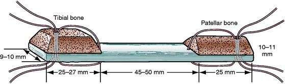
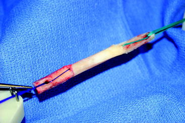
In order to visualize our fixation strategies, the reader should have an understanding of the shape of our graft. Through a slightly medial parapatellar incision, the peritenon of the patella tendon is elevated and the tendon is visualized from its medial to lateral border. We use a ruler not only to confirm the tendon to be 30 to 33 mm in width, but also to measure the distance between longitudinal cuts through the full thickness of the patella tendon 10 to 11 mm apart. We use a combination of an oscillating saw and osteotomes to harvest a trapezoidal-shaped bone block from the tibial tubercle, which is 25 to 27 mm long, and a triangular-shaped bone block from the patella, which is 25 mm long (Fig. 48-1). The bone blocks are trimmed with a rongeur to pass through either a 10- or 11-mm sizing sleeve. The overall length of the graft is usually 90 to 105 mm. Two stay sutures are passed through each bone block and tendon using #1 absorbable monofilament (PDS) for the femoral block and #5 nonabsorbable braided suture for the tibial end of the graft. The absorbable suture in the femoral bone block allows us to cut the suture flush with the skin if it will not pull out. The bone block with the better bone, which is usually the tibial tubercle block, is directed toward the femoral canal with the #1 sutures (PDS). The graft is stretched on a graft board with 20 pounds of tension for 10 to 15 minutes while covered by an antibiotic-soaked gauze (Fig. 48-2).
Screw Selection
A cannulated, round-headed, partially threaded screw is used for the femoral side to protect the graft from laceration at the bone plug–tendon interface. Any number of manufacturers produce round–headed, partially threaded screws.4 A fully threaded screw or a screw with a squared-off head may put the tendinous portion of the graft at risk. We use a fully threaded screw for fixation in the tibial tunnel. The extra threads provide additional fixation, and a round head is not needed distal to the screw and graft.
The literature has shown that the effect of screw diameter is interrelated to the tunnel diameter and the gap size between the graft bone plug and tunnel.5–7 We make our tunnels the same size as the sizers through which our graft bone plugs pass, usually 10 or 11 mm. In both the femoral and tibial tunnels, our first choice for screw diameter is 1 mm less than the tunnel diameter for metal screws, usually 9 or 10 mm, and the same as the tunnel diameter for bioabsorbable screws, usually 10 or 11 mm.
Length of interference screws has not been correlated to fixation strength with BPTB grafts.8–10 We try to match the length of the screw to the length of the graft bone plug. If the surgeon harvests a full 25 mm of bone plug and makes a tunnel deep enough to accommodate the whole plug, he or she should fix the full length of the plug within the tunnel. We frequently use 25-mm-long metal or 28-mm-long bioabsorbable screws in the femoral tunnel, and we use 25-mm-long metal or 28-mm-long bioabsorbable screws in the tibial tunnel.
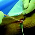
Metal interference screws have a proven track record for secure fixation of BPTB ACLR and are well tolerated by the human body. However, complications related to this hardware option include laceration of the graft on insertion and interference with postoperative magnetic resonance imaging (MRI) scans of the knee, as well as potentially blocking tunnels for revision ACLR. The influence on MRI has been lessened with the use of titanium screws compared with the stainless steel screws initially used. Graft laceration by the screw has not been a problem because we use a plastic sheath to protect both the ACL graft and native posterior cruciate ligament (PCL) when inserting both metal and bioabsorbable screws into the notch and femoral tunnel (Fig. 48-3, A and B).
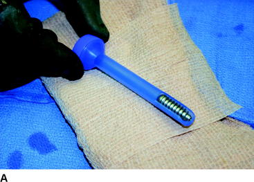
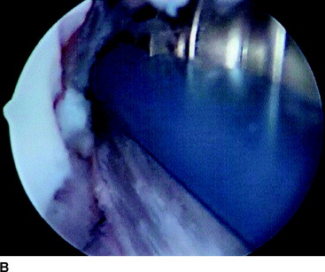
Fig. 48-3 A, Graft protector for screw insertion. B, The plastic sheath protects the graft from laceration.
Bioabsorbable screws were introduced as a device to provide secure mechanical fixation in the interval prior to biological fixation of the graft and then leave the body with no residual foreign material. They create less interference with MRI scans of the knee, cause less graft trauma, and allow easier revision by disappearing or by just drilling through any remnant. The disadvantages of these implants were reported to be breakage and soft tissue reaction due to poor biocompatibility. Poly-L-lactic acid (PLLA) screws are most commonly used today. Studies have shown screw breakage on insertion to be uncommon and, when it does occur, does not cause adverse effects.11,12 A handful of cases of late screw fragmentation have been reported, and soft tissue reactions to PLLA are rare.13,14 The low rate of soft tissue reactions to PLLA is due to the slow rate of degradation in vivo. Studies show persistence of these screws years after insertion.15,16
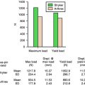
The tensile strength of cancellous and cortical bone is less than that for titanium or PLLA. For metal and bioabsorbable screws of the same size and shape in the same anatomical and biological scenario, the failure strength will be the same because the construct will fail at the weaker cancellous bone first.3 No significant difference was found when metal and bioabsorbable interference screws in BPTB ACLR were compared with regard to initial strength of fixation as tested with single load and cycle load to failure (LTF).1–3,17,18 Walton showed no difference during a period of interval healing when examining sheep specimens 4 to 52 weeks after interference screw fixation in BPTB ACLR.19 McGuire et al and Kaeding et al showed no significant difference of motion, laxity, or instability between metal and bioabsorbable interference screw fixation of BPTB ACLR as much as 2.4 years postoperatively.11,12
Bone Tunnel Preparation
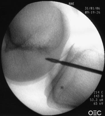
Much has been written to describe proper tunnel placement in both the tibia and lateral femoral condyle. We use a targeting guide for the tibial tunnel with the goal of the guidewire exiting in the posterior portion of the native ACL footprint, just medial to the anterior horn of the lateral meniscus, centered medial to lateral between the tibial spines. The graft harvest incision is retracted medially to place the distal entry site halfway between the anterior cortical ridge and the medial border of the tibia. We use a guide set at 55 degrees to create a tibial tunnel 50 to 55 mm long. After placing the guidewire, we use intraoperative fluoroscopy to confirm the position of the guidewire within the tibia. On the initial flexed lateral image, the guidewire penetrates the proximal cortex of the tibia with approximately 20% to 40% of the anteroposterior length anterior to the guidewire. A second lateral fluoroscopic image is obtained with the knee fully extended. A line extended from the guidewire should be just posterior to Blumensaat’s line (Fig. 48-4). The guidewire is removed and repositioned if it does not meet the just-mentioned criteria. Once the guidewire is positioned appropriately and no impingement is confirmed, the first reamer, which is 2 mm smaller than the graft size and final tunnel diameter, is passed. Bone reamings are collected to use as autograft for the patella–bone plug defect at the conclusion of the case. The tibial tunnel is then expanded incrementally 2 mm up to the final diameter.
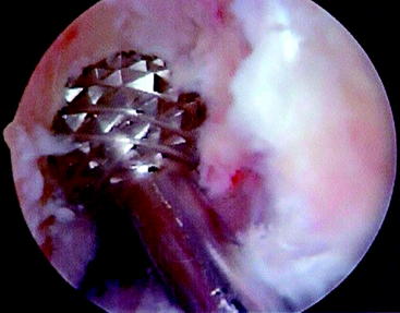
The femoral tunnel is placed on the medial aspect of the lateral femoral condyle with just 1 to 2 mm of cortical bone posterior to the tunnel.20–22 A 5-mm offset femoral guide is used transtibially for femoral tunnel placement (Fig. 48-5). The knee must be flexed to a position such that the guidewire is not directed posteriorly to exit the posterior portion of the femur. The guidewire is placed using the offset guide. The position just anterior to the posterior wall is confirmed on a true lateral fluoroscopic image of the distal femur. A small, 7- or 8-mm acorn reamer is passed to a depth of 35 to 40 mm after proper guidewire position is confirmed. The guidewire is repositioned in the anterior portion of the femoral tunnel and gently tapped into the depth of the tunnel to secure it in a slightly anterior eccentric position within the femoral tunnel. Progressively larger reamers or dilators are used to enlarge the tunnel to its final diameter and avoid posterior wall blowout. A motorized shaver is introduced through the anteromedial portal to remove all loose bone-reaming debris from the posterior joint space and notch. A rasp is placed through the tibial tunnel and up into to the femoral tunnel to confirm posterior wall by palpation and then to rasp smooth the anterior aperture of the femoral tunnel (Fig. 48-6). The arthroscope is then removed from the anterolateral portal and inserted through the tibial tunnel, across the knee joint, and into the femoral tunnel to visually check continuity of the posterior wall. The knee is hyperflexed, and a Beath pin is placed through both tunnels and the femoral cortex to exit the anterior thigh. The Beath pin then brings a passing suture loop across the knee, and the passing suture loop is used to bring the leading graft sutures through the knee to exit the anterior thigh. The graft is brought into the knee.
Relative Position of Screw and Graft within Tunnel
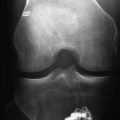
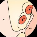
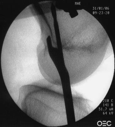
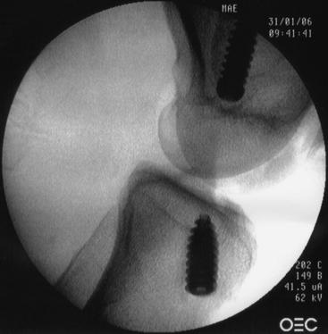
The femoral tunnel is placed on the medial aspect of the lateral femoral condyle with just 1 to 2 mm of cortical bone posterior to the tunnel.20–22 A 5-mm offset femoral guide is used transtibially for femoral tunnel placement. A small (8-mm) acorn reamer is used followed by progressively larger reamers to avoid posterior wall blowout. The tendinous portion of the graft does not fill the aperture of the femoral tunnel, so its relative position within the tunnel can be directed. A soft tissue grasper is inserted through the anteromedial portal and used to rotate the graft bone plug prior to its final entry within the femoral tunnel. We place the cortical side of the bone plug in the posterolateral aspect of the femoral tunnel, placing the tendinous portion of the graft at the posterolateral portion of the aperture. The guidewire and screw are placed opposite the graft in the anteromedial portion of the tunnel (Fig. 48-7, A and B). With regard to depth within the tunnel, the graft bone plug is usually recessed 1 to 2 mm within the femoral tunnel and the interference screw is placed with the head flush with the distal end of the graft bone plug, with no hardware overhanging the graft bone plug to abrade the tendon (Fig. 48-8, A and B). Prior to inserting the graft within the knee, we use a rasp to smooth the anterior lip of the femoral tunnel opening.
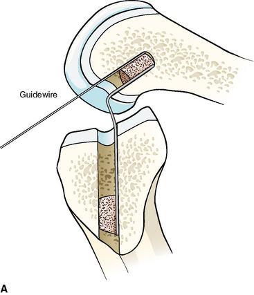
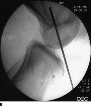
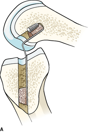
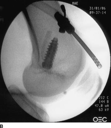
Fig. 48-8 A, Screw parallel to and the same length as the bone block. B, Parallel screw placement by x-ray.
The depth that the tibial bone plug comes to rest within the portion of the tibial tunnel is dictated by the length of the graft and the position in which the femoral bone plug was fixed. There are choices with regard to the rotation of the cortical-cancellous surfaces and the surfaces for healing versus fixation. We choose to rotate the graft bone plug so that the cortical surface comes to lie anteriorly within the tibial tunnel, and we place the tibial interference screw anterior to the graft bone plug (Fig. 48-9). Rupp et al tested bone plugs and found no difference in initial fixation strength when the screw was placed in either the cortical or the cancellous surfaces of the graft bone plug.23 However, the bone density of the proximal tibial metaphysis is lower than that of the distal femur, and we want to place the interference screw between the harder cortical surface of the graft and the harder anterior cortex of the anterior tibia, similar to a wedge.24 Furthermore, this places the cancellous portion of the graft bone plug next to the cancellous bone of the tibial tunnel to facilitate bone–bone healing. Yoshiya et al demonstrated incorporation of the bone plug at the bone–bone interface at 12 weeks when the cancellous portion of the bone plug was placed next to the bone tunnel and the interference screw was placed at the cortical side of the bone plug.25
Parallelism and Divergence
This goal can be accomplished when both the femoral tunnel reaming and femoral interference screw insertion occur through the same path. Three options meet this criterion. Early anatomical ACLR used a distal lateral thigh exposure for a two-incision reconstruction. The femoral tunnel was drilled from outside-in, and the interference screw followed. With or without a guidewire, the interference screw could reliably be positioned parallel to the tunnel and bone block. Lemos et al reported 0 of 25 cases to have divergence with this technique.26 Cerullo and Puddu described using an arthroscope to view directly down the femoral tunnel from the outside to confirm parallel position of the femoral screw within the femoral tunnel, and he stated it could be done as well in the tibial tunnel.27 We frequently resort to this two-incision technique if we are doing a revision or have a long graft (greater than 105 mm) and a graft–tunnel mismatch.
One-incision, arthroscopic-assisted ACLR is more commonly performed today, and most femoral tunnels today are guided by wires through tibial tunnels and reamed through those same tibial tunnels. In a manner similar to that described by Paulos, Brodie et al inserted the femoral screw into the joint through an anteromedial portal, but screw insertion into the femoral canal was carried out with the screwdriver passing anterior to the distal bone plug in the tibial tunnel, parallel to the path taken by the femoral canal reamers. No patient had screw/tunnel divergence greater than 15 degrees in either plane.28 Schroeder showed only 4% divergence when passing a 7-mm interference screw and driver through the tibial tunnel, tapping the distal bone plug as it passed, into the parallel femoral tunnel.29 A third option involves both reaming and placing the femoral screw through an anteromedial portal with the knee in a hyperflexed position.
Despite the fact that at present most femoral tunnels are reamed through a tibial tunnel, most femoral interference screws are placed through an anteromedial portal. Although parallelism is the goal, divergence of the femoral screw and tunnel results can be made acceptable. Efforts to minimize this divergence are made, as biomechanical studies have shown little difference in the pullout strength when divergence is less than 15 degrees as compared with parallel, but pullout strength is much lower when divergence is greater than 15 degrees.30–32 In addition to the poor initial fixation, divergence can also cause intraoperative complications such as guidewire bending, guidewire breakage with inadvertent hardware retention, or graft bone block fracture.33
We use several techniques to minimize our femoral screw/tunnel divergence. The graft has already been passed, and the femoral bone block rests within the femoral tunnel. We establish an accessory anteromedial portal, which is placed lower than a traditional anteromedial portal and just medial to the border of the patellar tendon. No additional skin incision is needed, and the arthrotomy for this portal is carried out through the already open anterior incision for patella tendon harvest. At this point the knee is taken to a position of deeper flexion than that with which the femoral tunnel was drilled. We have not found our arthroscopic visualization of the opening of the femoral tunnel to be limited by this change in position. Initially, a rigid “trailblazer” is passed through this portal and up into the anterior portion of the femoral tunnel, just anterior to the graft, in an effort to make an opening for the first few threads of the interference screw to be placed later. This accomplishes the same result as passing a few threads of a tap. Then a guidewire is inserted through this same portal, across the femoral notch, and into the femoral tunnel anterior to the graft bone plug. The guidewire can be felt to slide effortlessly within the femoral tunnel. At this point a sterile draped fluoroscopy unit is brought within the operative field, and the position of the guidewire within and parallel to the femoral tunnel and bone block is confirmed on lateral fluoroscopic images. Rodin and Levy have published a similar technique, with only 3% of the 62 cases having significant divergence greater than 15 degrees.34 Finally, we ensure that the guidewire remains freely mobile during screw insertion to prevent guidewire bending or breakage, with some similarities to the advancing guidewire technique as described by Ha et al.33 We remove the guidewire prior to completing the last few turns of the screw within the femoral tunnel. If for some reason the screw does not insert appropriately, or if the wire is bending or the screw is divergent, the screw can be removed, the guidewire can be repositioned or replaced if bent, and the same-size screw can be reinserted to achieve the same fixation pullout strength as a screw inserted only once.35
Graft–Tunnel Mismatch
Shaffer et al and Olszewski et al report techniques to prevent mismatch using intraoperative measurements and simple mathematical equations to direct the length of tibial tunnel required prior to creating that tunnel.36,37 The tibial guide used in this technique provides a measurement of the length of the tibial tunnel prior to the tunnel being drilled. Central to these ideas is that the length of the tibial tunnel and intraarticular distance must be greater than or equal to the length of the patella tendon and tibial bone plug in order for the tibial bone plug to come to rest within the tibial tunnel. The tibial tunnel length is the only nonanatomical variable. With a long patella tendon, these formulas would suggest a long tibial tunnel with a high angle down the tibial shaft. Angles in excess of 60 degrees are not practical because they disrupt the pes anserina and make creation of femoral tunnels difficult to achieve without blowing out the posterior cortex.37
Others recommend always using a standard tibial tunnel angle of 55 degrees, creating a tunnel length of 50 to 55 mm, and being satisfied that this will work in the majority of cases.20,38 Options for dealing with the problem after the femoral and tibial tunnels have been created have been described as well, including recessing the femoral bone plug deeper within the femoral tunnel, rotating the graft along its long axis to shorten the length of the patella tendon, flipping the tibial bone plug back onto the tendinous portion of the graft, and achieving alternative tibial fixation.39–41 Staples or suture posts can be used when solid fixation with interference screws cannot be achieved.
Our technique for preventing graft–tunnel mismatch includes preoperative assessment of the lateral radiograph for patella alta or baja. We harvest our graft and measure its total and tendinous lengths prior to creating tunnels. Our grafts are usually 90 to 105 mm in length, with the patella tendon usually 40 to 55 mm in length. Reported mean lengths of patella tendons range from 43 to 48 mm, with outer limits including tendons of 33 to 63 mm.36–38 Graft–tunnel mismatch is more frequent with patella tendon length greater than 50 mm.36 When our total graft is longer than 105 mm, we will frequently plan for a two-incision technique and create our femoral tunnel using an outside-in fashion. With a two-incision technique, bitunnel interference screw fixation is not a problem, as the total tunnel length is usually 120 mm.36,42 Otherwise, we proceed with standard tunnel placement and preparations. We drill a tibial tunnel with a 55-degree angle, drill the femoral tunnel through the tibial tunnel, confirm femoral guidewire placement with fluoroscopy, and prepare a femoral tunnel 35 to 40 mm deep. The anterior edge of the femoral tunnel is rasped smooth, and the posterior wall is palpated to ensure integrity. The graft is passed into the femoral tunnel, with the femoral bone plug recessed 1 or 2 mm from the aperture. The graft is fixed at this position if the tibial bone plug rests within the tibial tunnel. Our first step for mismatch if the tunnels have already been created is to recess the graft 5 to 10 mm within the femoral tunnel. As with all femoral interference screws that we place, we confirm parallelism with fluoroscopic images of the guidewire prior to screw insertion to a recessed femoral bone plug.
Mismatch with too short a graft is uncommon because intraarticular distance between the tunnel apertures ranges from 20.4 to 26 mm, whereas the mean lengths of patella tendons range from 43 to 48 mm.36–38 If the graft is short and the tibial bone plug comes to rest deep within the tibial tunnel and near the articular surface, we confirm placement of the guidewire past the tibial bone plug and into the joint with arthroscopic visualization. We also confirm that the screw is not placed too deep within the joint with the arthroscope. In this situation, a Hewson Ligament Button can be used as backup cortical fixation.
Extremes of Bone Density
Softer bone can be more problematic, and thus more options are available. As stated, our initial reamer is 2 mm smaller than our final tunnel diameter. If the bone feels soft in the work leading up to this point, we will use serial dilators in 0.5-mm increments to increase the size of the tunnel and compact the bone surrounding the tibial tunnel. A tap is not used prior to inserting the screws. Decreased bone mineral density has been shown to be correlated with decreased insertional torque and failure load.5,24,43 Even without a torque wrench, the surgeon’s own forearm can indicate a difference in insertional torque in soft bone. With soft bone, our choice for screw diameter will be 1 mm greater than usual with normal bone—the same as the tunnel diameter for metal screws, usually 10 or 11 mm—and 1 mm greater than the tunnel diameter for bioabsorbable screws, usually 11 or 12 mm for a 10- or 11-mm tunnel. However, patients with soft bones frequently have a smaller patella tendon and we frequently harvest a 9-mm graft, making the tunnels 9 mm, and the screws are 9 mm for metal and 10 mm for bioabsorbable. If the surgeon and his or her own forearm do not believe that the first screw placed has enough insertional torque, then the screw should be removed and replaced with a screw 1 mm larger in diameter. This can be repeated a second time, but if the fixation is poor at this point, other fixation strategies must be considered.
Our backup femoral fixation in cases of poor interference screw fixation or posterior wall blowout is Endobutton fixation (Acufex, Smith & Nephew, Mansfield, MA). The graft is removed from the knee in the case of poor screw fixation and prepared by connecting the Endobutton to the graft bone plug with two or three loops of #5 nonabsorbable braided suture passed through drill holes in the bone plug and woven through the tendinous portion of the graft. The femoral tunnel is prepared by passing the last reamer through the femoral tunnel all the way to but not through the lateral cortex of the femur. A 2.4-mm guidewire and then a 4.5-mm reamer are passed through the lateral cortex of the femur. Leading and trailing sutures are placed in the peripheral holes of the Endobutton. The graft is placed in the knee. The Endobutton is led out of the 4.5-mm opening in the lateral cortex and then deployed by tugging on the trailing suture. The graft is tensioned with sutures in the opposite end of the graft to confirm deployment of the Endobutton and secure fixation of the femoral end of the graft. The position of the Endobutton is further confirmed with anteroposterior and lateral fluoroscopic images. An interference screw can be placed in the femoral canal in the standard fashion if additional fixation is desired.44
Our preferred backup on the tibial side is a Hewson ligament button placed over the distal opening of the tibial tunnel under a periosteal flap. The #5 nonabsorbable braided sutures attached to the tibial bone plug and distal graft tendon are led through separate openings in the button. A posterior drawer moment is placed about the knee with the knee in approximately 60 degrees of flexion. The sutures are tensioned as appropriate, and the knee is passed through 20 rotations of range of motion and then tied over the button. The periosteal flap is then closed over the button. The button technique allows good cortical bone fixation as a backup to soft bone.44 Additionally, a suture post technique with nonabsorbable sutures tied over a screw and washer can be used. If this is used as a backup for femoral fixation, a separate second incision centered over the distal lateral thigh will be necessary to place the screw in the distal femur. All three of these femoral fixation techniques have been shown to have no difference in ultimate failure load.45
Another form of “soft” bone occurs with graft bone block fracture. This can occur intraoperatively during screw insertion or postoperatively during rehabilitation or repeat injury.46 When the femoral bone block is fragmented, the graft can be reversed and the patellar bone block can be inserted and fixed within the femoral tunnel. The opposite tendinous portion of the graft can be captured with nonabsorbable suture and then tied over a button or post on the tibia. If the tibial bone plug fractures, a similar scenario without the graft reversal can be attempted. If these techniques do not achieve a stable knee, the remaining options include obtaining a new autograft from another source (e.g., quadriceps, hamstring) or using an allograft to complete the ACLR.
1 Caborn DN, Urban WPJr, Johnson DL, et al. Biomechanical comparison between BioScrew and titanium alloy interference screws for bone-patellar tendon-bone graft fixation in anterior cruciate ligament reconstruction. Arthroscopy. 1997;13:229-232.
2 Rupp S, Seil R, Schneider A, et al. Ligament graft initial fixation strength using biodegradable interference screws. J Biomed Mater Res. 1999;48:70-74.
3 Beevers DJ. Metal vs. bioabsorbable interference screws: initial fixation. Proc Inst Mech Eng [H]. 2003;217:59-75.
4 Bach BR. Observations on interference screw morphologies. Arthroscopy. 2000;16:E10.
5 Brown GA, Pena F, Grontvedt T, et al. Fixation strength of interference screw fixation in bovine, young human, and elderly human cadaver knees: influence of insertion torque, tunnel-bone block gap, and interference. Knee Surg Sports Traumatol Arthrosc. 1996;3:238-244.
6 Shapiron JD, Jackson DW, Aberman HM, et al. Comparison of pullout strength for seven- and nine-millimeter diameter interference screw size used in anterior cruciate ligament reconstruction. Arthroscopy. 1995;11:596-599.
7 Kohn D, Rose C. Primary stability of interference screw fixation. Am J Sports Med. 1994;22:334-338.
8 Black KP, Saunders MM, Stube KC, et al. Effects of interference fit screw length on tibial fixation for anterior cruciate ligament reconstruction. Am J Sports Med. 2000;28:846-849.
9 Pomeroy G, Baltz M, Pierz K, et al. The effects of bone plug length and screw diameter on the holding strength of bone-tendon-bone grafts. Arthroscopy. 1998;14:148-152.
10 Kao JT, Tibone JE, Shaffer B. The pullout strength and use of tibial interference screws during endoscopic ACL reconstruction surgery. Am J Knee Surg. 1995;8:42-47.
11 McGuire DA, Barber FA, Elrod BF, et al. Bioabsorbable interference screws for graft fixation in anterior cruciate ligament reconstruction. Arthroscopy. 1999;15:463-473.
12 Kaeding C, Farr J, Kavanaugh T, et al. A prospective randomized comparison of bioabsorbable and titanium anterior cruciate ligament interference screws. Arthroscopy. 2005;21:147-151.
13 Ambrose CG, Clanton TO. Bioabsorbable implants: review of clinical experience in orthopedic surgery. Ann Biomed Eng. 2004;32:171-177.
14 Bostman OM, Pihlajamaki HK. Adverse tissue reactions to bioabsorbable fixation devices. Clin Orthop Relat Res. 2000;371:216-227.
15 Morgan CD, Gehrmann RM, Jayo MJ, et al. Histologic findings with a bioabsorbable anterior cruciate ligament interference screw explant after 2.5 years in vivo. Arthroscopy. 2002;18:E47.
16 Radford MJ, Noakes J, Read J, et al. The natural history of a bioabsorbable interference screw used for anterior cruciate ligament reconstruction with a 4-strand hamstring technique. Arthroscopy. 2005;21:707-710.
17 Seil R, Rupp S, Krauss PW, et al. Comparison of initial fixation strength between biodegradable and metallic interference screws and a press-fit fixation technique in a porcine model. Am J Sports Med. 1998;26:815-819.
18 Kousa P, Jarvinen TL, Kannus P, et al. Initial fixation strength of bioabsorbable and titanium interference screws in anterior cruciate ligament reconstruction. Biomechanical evaluation by single cycle and cyclic loading. Am J Sports Med. 2001;29:420-425.
19 Walton M. Absorbable and metal interference screws: comparison of graft security during healing. Arthroscopy. 1999;15:818-826.
20 Fineberg MS, Zarin B, Sherman OH. Practical considerations in anterior cruciate ligament replacement surgery. Arthroscopy. 2000;16:715-724.
21 Barrett GR, Treacy SH. The effect of intraoperative isometric measurement on the outcome of anterior cruciate ligament reconstruction: a clinical analysis. Arthroscopy. 2000;12:645-651.
22 Lintner DM, Dewitt SE, Moseley JB. Radiographic evaluation of native anterior cruciate ligament attachments and graft placement for reconstruction. A cadaveric study. Am J Sports Med. 1996;24:72-78.
23 Rupp S, Seil R, Krauss PW, et al. Cortical versus cancellous interference fixation for bone-patellar tendon-bone grafts. Arthroscopy. 1998;14:484-488.
24 Brand JCJr, Pienkowski D, Steenlage E, et al. Interference screw fixation strength of a quadrupled hamstring tendon graft is directly related to bone mineral density and insertion torque. Am J Sports Med. 2000;28:705-710.
25 Yoshiya S, Nagano M, Kurosaka M, et al. Graft healing in the bone tunnel in anterior cruciate ligament reconstruction. Clin Orthop Relat Res. 2000;376:278-286.
26 Lemos MJ, Albert J, Simon T, et al. Radiographic analysis of femoral interference screw placement during ACL reconstruction: endoscopic versus open technique. Arthroscopy. 1993;9:154-158.
27 Cerrullo G, Puddu G. Arthroscopic placement of the interference screw for anterior cruciate ligament reconstruction. Arthroscopy. 1993;9:712-713.
28 Brodie JT, Torpey BM, Donald GDIII, et al. Femoral interference screw placement through the tibial tunnel: a radiographic evaluation of interference screw divergence angles after endoscopic anterior cruciate ligament reconstruction. Arthroscopy. 1996;12:435-440.
29 Schroeder FJ. Reduction of femoral interference screw divergence during endoscopic anterior cruciate ligament reconstruction. Arthroscopy. 1999;15:41-48.
30 Pierz K, Baltz M, Fulkerson J. The effect of Kurosaka screw divergence on the holding strength of bone-tendon-bone grafts. Am J Sports Med. 1995;23:332-335.
31 Lemos MJ, Jackson DW, Lee TQ, et al. Assessment of initial fixation of endoscopic interference screws with divergent and parallel placement. Arthroscopy. 1995;11:37-41.
32 Jomha N, Raso V, Leung P. Effect of varying angles on the pullout strength of interference screw fixation. Arthroscopy. 1993;9:580-583.
33 Ha KI, Kim SH, Ahn JH. The HAKI technique of femoral interference screw insertion. Arthroscopy. 1999;15:110-114.
34 Rodin D, Levy IM. The use of intraoperative fluoroscopy to reduce femoral interference screw divergence during endoscopic anterior cruciate ligament reconstruction. Arthroscopy. 2003;19:314-317.
35 Matthews LS, Lawrence SJ, Yahiro MA, et al. Fixation strengths of patellar tendon-bone grafts. Arthroscopy. 1993;9:76-81.
36 Shaffer B, Gow W, Tibone JE. Graft-tunnel mismatch in endoscopic anterior cruciate ligament reconstruction: a new technique of intraarticular measurement and modified graft harvesting. Arthroscopy. 1993;9:633-646.
37 Olszewski A, Miller M, Ritchie J. Ideal tibial tunnel length for endoscopic anterior cruciate ligament reconstruction. Arthroscopy. 1998;14:9-14.
38 Denti M, Bigoni M, Randelli P, et al. Graft-tunnel mismatch in endoscopic anterior cruciate ligament reconstruction. Intraoperative and cadaver measurement of the intra-articular graft length and the length of the patellar tendon. Knee Surg Sports Traumatol Arthrosc. 1998;6:165-168.
39 Taylor DE, Dervin GF, Keene GCR. Femoral bone plug recession in endoscopic anterior cruciate ligament reconstruction. Arthroscopy. 1996;12:513-515.
40 Auge WKII, Yifan K. A technique for resolution of graft-tunnel length mismatch in central third bone-patellar tendon-bone anterior cruciate ligament reconstruction. Arthroscopy. 1999;15:877-881.
41 Barber FA, Spruill B, Sheluga M. The effect of outlet fixation on tunnel widening. Arthroscopy. 2003;19:485-492.
42 Stapleton TR, Waldrop JI, Ruder CR, et al. Graft fixation strength with arthroscopic anterior cruciate ligament reconstruction. Two-incision rear entry technique compared with one-incision technique. Am J Sports Med. 1998;26:442-445.
43 Pena F, Grontvedt T, Brown GA, et al. Comparison of failure strength between metallic and absorbable interference screws. Influence of insertion torque, tunnel-bone block gap, bone mineral density, and interference. Am J Sports Med. 1996;24:329-334.
44 Barrett GR, Papendick L, Miller C. Endobutton button endoscopic fixation technique in anterior cruciate ligament reconstruction. Arthroscopy. 1995;11:340-343.
45 Honl M, Carrero V, Hille E, et al. Bone-patellar tendon-bone grafts for anterior cruciate ligament reconstruction: an in vitro comparison of mechanical behavior under failure tensile loading and cyclic submaximal tensile loading. Am J Sports Med. 2002;30:549-557.
46 Berg EE. Autograft bone-patella tendon-bone plug comminution with loss of ligament fixation and stability. Arthroscopy. 1996;12:232-235.