Implantable Cardioverter Defibrillators
Technical Aspects
System Elements
The physical components of the implanted system consist of the ICD generator, the pacing and sensing electrodes, and one or more high-energy electrodes. The titanium casing of the ICD generator usually constitutes one of the high-energy electrodes. The electrodes, or leads, attach to the generator header through sealed connectors. Until recently, the ICD leads all divided into one bipolar IS-1 (bradycardia) and one or two defibrillation (DF)-1 (high energy) connectors that are inserted into the ICD generator header. A fully approved (March 15, 2010) International Organization for Standardization (ISO) standard (ISO 27186) implemented by several manufacturers is the DF-4 connector standard that is also 3.2 mm, but combines the connection into a single connector for both low-energy (pacing and sensing) and high-energy (shocking) electrode function. The older IS-1/DF-1 lead design is bulky in the device pocket and adds to the length of the lead. In addition, the trifurcation or bifurcation of the lead also creates the potential for errors in making connections to the header. A similarly constructed (IS-4) connection standard is also implemented for quadripolar low-voltage leads. This standard is implemented only for left ventricular cardiac venous leads and permits noninvasive programming of the pacing vectors after the incision is closed. The IS-4 for LV leads and DF-4 for ICD leads are similar but distinct enough not to allow connection errors in the header (Figure 115-1).
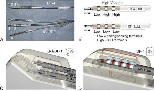
Figure 115-1 DF-4/IS-4 lead design. A, DF-4 lead design eliminates the yoke and the redundant lead formation seen in the IS-1/DF-1 design. 1, distal pace/sense electrode; 2, proximal pace/sense electrode; 3, distal DF-1 coil electrode; 4, proximal DF-1 coil electrode. B, IS-4 lead design is similar to DF-4 lead design except that all electrodes are pace/sense low-voltage electrodes. C, IS-1/DF-1 lead connector has three setscrews with the sealing rings built on the lead. D, DF-4/IS-4 connector has a single setscrew that secures on the tip of the lead with spring contacts for the ring and DF electrodes. Inside the DF-4 connector, there are double-sealing rings (blue) between electrodes to secure good isolation between the high- and low-voltage electrode insulation.
Nonthoracotomy or Transvenous Leads
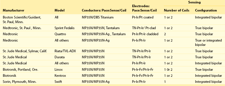
Nonthoracotomy ICD leads (NTLs) were designed to carry high defibrillation energy to the inside of the heart. These leads can have a dedicated proximal sensing/pacing ring electrode (true bipolar) or use the distal high-voltage shocking coil as the proximal sensing/pacing electrode (integrated bipolar). True bipolar leads usually offer better discrimination for sensing, being less susceptable to far-field oversensing and postshock undersensing. On the other hand, integrated bipolar leads offer better defibrillation performance because of the shorter tip-to–distal coil distance. NTL leads can have one right ventricular (single coil) or two (dual coil) high-voltage shocking electrodes. The distal coil is usually placed in the right ventricular apex, and the proximal coil is placed in the superior vena cava. Although the dual-coil ICD lead system have predominated in the United States and Europe, its clinical superiority over the single-coil lead system is not well established. Defibrillation efficiancy is slightly improved, usually by 1 to 3 J.1 The effect of the dual-coil ICD lead on defibrillation threshold is multifactorial: altered defibrillation electrical field vector, lowered shock impedance, and an on shortening the shock waveform duration. However, this small benefit needs to be weighed against the added complexity of lead construction and its potential effect on lead reliability, as well as the potential for more complex extraction when needed. In addition, the lower right atrial position of the proximal coil, in the case of severely enlarged right ventricle, can increase DFT by a negative current vector effect. In other patients, there is a need to implant other coils (coronary sinus, middle cardiac vein, subcutaneous coil, or azygous coil) when maximal shocks are ineffective; this is almost always more effective in reducing the required defibrillation energy by 5 to 15 J.2
Invariably, NTLs have a high-energy coil located near the distal end and lying within the right ventricular cavity. Manufacturers have released NTLs with similar construction, although some details differ (Table 115-1). The physics of DC flow, however, requires at least one other electrode to complete the shocking circuit. The development of smaller ICD generators has allowed for pectoral implantation, which has enabled the use of the generator casing as the second electrode (i.e., “hot can”). An animal study compared the defibrillation efficacy of a hot can ICD system placed in the left pectoral or subaxillary location with a right pectoral location, and left or right abdominal locations. The left pectoral and axillary subcutaneous positions were superior to all other locations. The right pectoral location was superior to either abdominal location. These results imply that alternative ICD implantation sites are feasible in the event of an inability to implant a left prepectoral device: left subclavian venous occlusion, history of left mastectomy or radiation, left sided arteriovenous fistula, or other reasons to avoid the left prepectoral area.
Tachyarrhythmia Detection
Atrial Lead Criteria
With placement of an atrial lead, the relation of atrial activity to the ventricular activity is available for analysis. If the data are accurate, with the caveats mentioned earlier concerning far-field signals, then AV dissociation during a rapid ventricular rhythm makes the diagnosis of ventricular tachycardia certain. If there is a 1 : 1 relation, the chance that the rhythm is ventricular tachycardia or supraventricular tachycardia is dependent on the ratio of the durations of the AV to the VA interval. Unfortunately, it is still possible to have atrial tachyarrhythmia and ventricular tachycardia at the same time. Atrial leads reduce the incidence but will not prevent inappropriate therapy because all algorithms are biased so that VF is rarely, if ever, missed. In one study, the addition of an atrial lead significantly decrease the rate of inappropriate supraventricular tachycardia (SVT) detection (as VT) and the rate of inappropriate therapy delivery, but it did not decrease the rate of ICD shock; however, this is not a consistent finding.3
Tachyarrhythmia Therapy
Pacing Therapy
All transvenous ICDs provide for bradycardia support with single-, dual-, or triple-chamber stimulation; however, the subcutaneous defibrillator only provides temporary postshock cardiac stimulation. The pacing mode, rate, and stimulation output is often separately programmable after a high-energy shock for a period to provide overdrive suppression of arrhythmias. Although many patients with ICDs receive dual-chambered rate-adaptive pacemakers, a small minority of these patients have an indication or need for pacing. The Dual Chamber and VVI Implantable Defibrillator (DAVID) trial examined the effect of pacing in the DDDR mode compared with ventricular backup pacing in patients who had ICD but no pacing indications. In these patients, DDDR pacing increased the combined end-point of hospitalization for congestive heart failure (CHF) or death.4 In the DAVID-II trial, atrial support pacing at AAI-70 was tested and showed no significant improvement in quality-of-life outcomes compared with VVI-40.5 As a result, patients without clear indications for antibradycardia pacing should be set to ventricular backup pacing. In patients with wide QRS duration and New York Heart Association functional class III or intravenous CHF, biventricular stimulation is appropriate. This therapy could also be applied in patients with less severe CHF or need for antibradycardia pacing.6
For some patients, a drawback to antitachycardia pacing is the potential for acceleration of the tachycardia to greater rates or to VF, so that high-energy shocks are required. Although 4% of patients experience acceleration of the tachycardia by antitachycardia pacing, this was not associated with any increase in mortality or incidence of syncopal events.7,8 Compared to shock therapy, antitachycardia pacing is delivered with no delay from the detection of the tachycardia (no capacitor to charge), with less morbidity (pain and ventricular stunning) and less battery usage. Once antitachycardia pacing therapy fails to terminate the tachyarrhythmia, shock therapy is delivered. In fact, in the EMPIRIC trial, standardized prespecified ICD programming with antitachycardia pacing during slow and fast ventricular tachycardia was at least as effective as physician-tailored programming without an increase in mortality or shock-related morbidity.9
Shock Therapy
The electrical shocks delivered by ICDs arise from the discharge of the capacitors through the heart via the high-voltage electrodes. Capacitor discharge follows an exponential decay (Figure 115-2), dependent on two variables: the capacitance, and the impedance of the electrode/patient body system. As either of these variables is increased, the voltage and current discharge decayed more slowly, producing a flatter waveform. One to three capacitors are commonly used in each generator, each rated at 106 to 480 µF capacitance and capable of a maximum voltage of 350 to 850 V. These capacitors are usually charged in parallel, to a programmable voltage up to the maximum. When discharged, however, these capacitors are configured in series, so that the total voltage is doubled or tripled depending on the number of capacitors to a maximum voltage of 750 to 850 V. Although the voltage is multiplied in the series configuration, the capacitance is reduced by the number of capacitors used; therefore, the resultant system capacitance is 120 to 150 µF for most currently available clinical devices. Lowering the capacitance of the system will have favorable clinical outcome by decreasing the discharge time. Because most lead impedance values are between 30 and 70 Ω, voltage decreases by 60% to 90% in 20 ms. The shock waveform (discussed later) is generated by the discharge of the capacitors through the electrode system to the patient. Unlike with antitachycardia pacing, ICD shocks can be associated with increased mortality and morbidity. In the Primary Prevention Parameters Evaluation trial, programming strategies to decrease ICD shocks by avoiding therapy for slow and nonsuatained ventricular tachcyardia and applying antitachycardia even to faster VT were associated with less morbidity including mortality.10
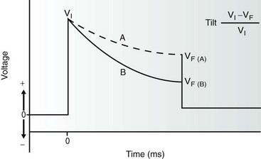
Figure 115-2 The monophasic waveform is created by truncation of a capacitor discharge and is the simplest implantable cardioverter defibrillator (ICD) waveform. The initial voltage (VI) is dependent on the charge placed on the capacitor. The waveform is truncated after a variable duration (depending on the manufacturer) when a certain final voltage (Vf) is reached. The rate of voltage decay (tilt) is inversely proportional to both the impedance of the lead system and the total capacitance in the ICD. Tilt is calculated according to the formula given such that waveform A demonstrates a lower tilt than waveform B.
Defibrillation Threshold and Safety Margin
The concept of the DFT is overly simplistic, because electrical defibrillation is best described as a sigmoid-shaped probability function (Figure 115-3). Nonetheless, the step-down DFT is a convenient clinical measurement to obtain during implantation and generally correlates with a probability of success of approximately 70% to 80%. The probability of success with this approach has significant clinical relevance, because appropriate implantation of ICDs requires a high confidence that the first shock will be successful. Historically, using epicardial leads and monophasic waveforms, a safety margin (a margin between the DFT and the maximal output of the ICD) of 10 J was considered minimal implantation criteria. More recent studies have suggested that, with biphasic shocks and NTLs, a margin of 1.9-fold the DFT energy provides a 95% probability of success. It is important to note that DFT testing is device- and lead-specific because the delivered energy is not the only parameter required to ensure successful defibrillation. Other parameters include lead/body impedance, waveform tilt, truncation, pulse duration, and positive and negative-phase peak voltage; these can all affect defibrillation success and are usually device- or lead-specific.11,12
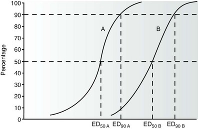
Figure 115-3 This graph shows the relationship between the probability of successful defibrillation and the intensity of the shock—that is, the greater the shock intensity, the higher the probability of success. The ED50 and ED90 refer to the shock intensities that result in successful defibrillation 50% and 90% of the time, respectively. In the examples given, curves A and B represent waveforms A and B with different defibrillation efficacy. Waveform A shows a greater efficacy (lower ED50 and ED90) than waveform B.
Monophasic Waveforms
The simplest defibrillator waveform is the monophasic waveform, in which the capacitor discharge is truncated before complete discharge of the capacitor, because the terminal voltage tail may prove proarrhythmic. Monophasic waveforms were used in early ICD generators and were effective in epicardial systems. The magnitude of a monophasic (or biphasic) shock is generally described by both the amplitude (peak voltage or current) and tilt of the waveform (see Figure 115-2). For example, a waveform whose amplitude is reduced to half the initial value has a 50% tilt.
Biphasic Waveforms
The most beneficial ICD innovation, from a viewpoint of defibrillation efficacy, was the development of the biphasic defibrillation waveform (Figure 115-4). This waveform consists of the capacitor discharge divided into two phases of opposite polarity. The first phase is identical to a monophasic waveform (although usually of a shorter duration) before the capacitor discharge is truncated. The electrical connection within the generator is then quickly reversed (usually within 2 to 3 µs), and the second phase is discharged in the opposite polarity for an additional period (usually 3 to 6 ms). Table 115-2 lists the biphasic waveform characteristics currently available in clinical ICDs.
Table 115-2
Summary of Biphasic Waveform Characteristics in Currently Available Commercial Implantable Cardioverter Defibrillators
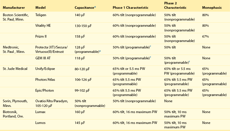
*Capacitance values may vary between models within a given manufacturer and older models may vary from these specifications. In models in which phase parameters are programmable, the value given is the default value programmed in the factory. When a range of values is given, it refers to different models offered by the same manufacturer.
†Applies only to the atrial shock tilt, the ventricular shocks are not tilt programmable.
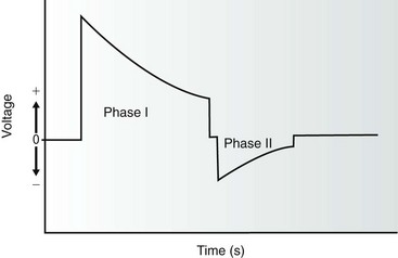
Figure 115-4 The biphasic waveform currently used in all current implantable defibrillators is composed of a capacitor discharge divided into two phases of opposite polarity. The duration of each phase is dependent on the manufacturer and is programmable in some devices. The initial voltage of the second phase is equivalent to the remaining voltage on the capacitor after truncation of phase I in most cases.
System Malfunction
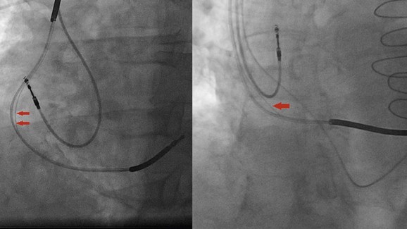
St. Jude Medical Riata and Riata ST leads were the subjects of class I recall because of higher-than-expected erosion in the silicone coating around its conductors. Insulation breaks seen in these leads could be caused by an inside-out or an outside-in abrasion (see Figure 115-5). The latter often occur close to the pocket and are often the result of lead contact with another part of the lead or the pulse generator. Although inside-out externalizations of the inner cables are not uncommon and can be visualized easily using fluoroscopy, they do not seem to place patients at significant risk of electrical dysfunction. However, outside-in abrasions are difficult to be identified using fluoroscopy and can result in shorting of the high voltage; this is not unique to the Riata lead family, nor is it a new failure mechanism.
Recent and Future Directions
Remote Monitoring
The development of the device monitoring systems with or without wandless communication has permitted the early diagnosis of arrhythmias and system malfunction from the patient’s home and with few limits to geographic location or distance from the monitoring physician. It has the potential to safely decrease clinic visits by 40% as seen in the TRUST trial.13 The CONNECT trial showed that remote monitoring with automatic clinician alerts can reduce the time between clinical events and clinical decisions, as well as the length of hospitalization stay. The ECOST trial showed that remote monitoring allows for early and reliable dectection of ICD lead failure and can reduce inappropriate ICD shocks and save battery life. However, other trials like the Tele-HF and EVATEL, did not show any significant benefit of remote monitoring on hospital readmission, all-cause mortality, and major clinical events. Additional studies are needed to evaluate whether monitoring will result in improvements in outcomes or reduction in heath care expendature.
Investigational Shock Waveform
Multiple triphasic waveform patterns were tested in animals and failed to improve shock efficacy in terminating ventricular fibrillation over biphasic waves.14 However, multiple serial monophasic shocks were shown to terminate monomorphic ventricular tachycardia with less total energy requirement and peak voltage compared to a single monophasic or biphasic shock in a canine myocardial infarction model.15 If these findings could be replicated in humans, it could translate into prolonged battery life, less pain, and less myocardial stunning and necrosis from the ICD shocks.
Subcutaneous Implantable Cardioverter Defibrillators
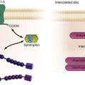
Subcutaneous ICDs were developed to address some of the problems and limitations of transvenous lead system ICDs (see Figure 115-6). These systems include but are not limited to: myocardial perforation and tamponade, vascular thrombosis and dissection, pulmonary embolism, brachial plexus injury, and percutaneous lead extraction. The Q-TRAK subcutaneous ICD lead (Boston Scientific) has two sensing electrodes separated by an 8-cm defibrillation coil producing three sensing vectors when connected to the defibrillation can. The lead is tunneled subcutaneously parallel to the left sternal border and is extended to connect to the subcutaneous ICD (SQ-RX Pulse Generator, Boston Scientific) that is placed in the anterior or midaxillary region around the fifth or sixth intercostal spaces. The ICD has a lithium-manganese oxide battery that can deliver an 80-J shock with a fixed 50% tilt. Cardiac signal sensing is automatically selected from the three available sensing vectors (distal-proximal electrodes, distal electrode-can, and proximal electrode-can) based on the analysis of the signal amplitude and signal-to-noise ratio. Arrhythmia detection algorithm uses morphology, beat-to-beat morphology, and QRS width analysis to define treatable arrhythmias. This algorithm is highly sensitive for the detection of ventricular arrhythmias similar to algorithms found in transvenous ICDs.16
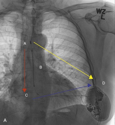
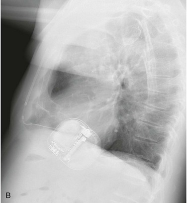
Figure 115-6 A, The subcutaneous implantable cardioverter-defibrillator (ICD) lead should run parallel to the left sternal border. A, Distal sensing electrode; B, 8-cm defibrillation coil; C, proximal sensing electrode; D, subcutaneous ICD device. There are three sensing vectors to capture myocardial signals. Blue arrow, primary sensing vector from the proximal electrode to the can; yellow arrow, secondary sensing vector from the distal electrode to the can; red arrow, alternate sensing vector from the distal to the proximal electrode. B, The subcutaneous ICD pulse generator is positioned in the anterior or midaxillary region.
References
1. Gold, M, Val-Mejias, J, Lennan, RB, et al. Optimization of superior vena cava coil position and usage for transvenous defibrillation. Heart Rhythm. 2008; 5:394–399.
2. Cesario, D, Bhargava, M, Valderrábano, M, et al. Azygos vein lead implantation: a novel adjunctive technique for implantable cardioverter defibrillator placement. J Cardiovasc Electrophysiol. 2004; 15(7):780–783.
3. Friedman, PA, McClelland, RL, Bamlet, WR, et al. Dual-chamber versus single-chamber detection enhancements for implantable defibrillator rhythm diagnosis. The Detect Supraventricular Tachycardia. Study. Circulation. 2006; 113(25):2871–2879.
4. The DAVID Investigators. Dual-chamber pacing or ventricular backup pacing in patients with an implantable defibrillator. JAMA. 2002; 288:3115–3123.
5. Wilkoff, BL, Kudenchuk, PJ, Buxton, AE, et al. The DAVID (Dual Chamber and VVI Implantable Defibrillator) II trial. J Am Coll Cardiol. 2009; 53:872–880.
6. Moss, AJ, Hall, WJ, Cannom, DS, et al. Cardiac-resynchronization therapy for the prevention of heart-failure events. N Engl J Med. 2009; 361(14):1329–1338.
7. Wathen, MS, DeGroot, PJ, Sweeney, MO, et al. Prospective randomized multicenter trial of empirical antitachycardia pacing versus shocks for spontaneous rapid ventricular tachycardia in patients with implantable cardioverter-defibrillators. Pacing Fast Ventricular Tachycardia Reduces Shock Therapies (PainFREE Rx II) trial results. for the PainFREE Rx II Investigators. Circulation. 2004; 110:2591–2596.
8. Wathen, MS, Sweeney, MO, DeGroot, PJ, et al. Shock reduction using antitachycardia pacing for spontaneous rapid ventricular tachycardia in patients with coronary artery disease. Circulation. 2001; 104:786–801.
9. Wilkoff, BL, Ousdigian, KT, Sterns, LD, et al. A comparison of empiric to physician-tailored programming of implantable cardioverter-defibrillators: results from the prospective randomized multicenter EMPIRIC trial. J Am Coll Cardiol. 2006; 48(2):330–339.
10. Wilkoff, BL, Williamson, BD, Stern, RS, et al. Strategic programming of detection and therapy parameters in implantable cardioverter-defibrillators reduces shocks in primary prevention patients: results from the PREPARE (Primary Prevention Parameters Evaluation) Study. J Am Coll Cardiol. 2008; 52:541–550.
11. Sweeney, MO, Natale, A, Volosin, KJ, et al. Prospective randomized comparison of 50/50% versus 65/65% tilt biphasic waveform on defibrillation in humans. Pacing Clin Electrophysiol. 2001; 24:60–65.
12. Schauerte, PN, Ziegert, K, Waldmann, M, et al. Effect of biphasic shock duration on defibrillation threshold with different electrode configurations and phase 2 capacitances: prediction by upper-limit-of-vulnerability determination. Circulation. 1999; 99:1516–1522.
13. Varma, N, Epstein, AE, Irimpen, A, et al. Efficacy and safety of automatic remote monitoring for implantable cardioverter-defibrillator follow-up: the Lumos-T Safely Reduces Routine Office Device Follow-up (TRUST) trial. Circulation. 2010; 122(4):325–332.
14. Davis, R, Malkin, R. Simultaneous comparison of many triphasic defibrillation waveforms. Open Biomed Eng J. 2012; 6:1–4.
15. Janardhan, A, Li, W, Gutbrod, S, et al. Low-energy three-stage electrotherapy delivered through implantable leads significantly reduces the cardioversion threshold in a canine model of persistent atrial fibrillation. Circulation. 2011; 124:A15917.
16. Gold, MR, Theuns, DA, Knight, BP, et al. Head-to-head comparison of arrhythmia discrimination performance of subcutaneous and transvenous ICD arrhythmia detection algorithms: the START study. J Cardiovasc Electrophysiol. 2012; 23(4):359–366.