Chapter 84 Implantable Cardioverter-Defibrillators
Device Technology and Implantation Techniques
Introduction
The implantable cardioverter-defibrillator (ICD) has emerged as the primary therapeutic option for the treatment of patients at risk for sudden cardiac death (SCD) caused by ventricular tachyarrhythmias.1–4 ICD devices were originally developed for the secondary prevention of SCD in patients with malignant ventricular arrhythmias and in survivors of SCD. Increasingly, ICDs are used for the primary prevention of SCD in an ever-expanding list of at-risk patient subgroups, which are discussed in this chapter. In addition, ICD systems have undergone a rapid technologic evolution to improve functionality and decrease the morbidity and mortality associated with implantation. These refinements in ICD lead and generator technology have led to a progressive expansion in their use. However, optimal device performance and follow-up require an intimate knowledge of these devices and their operations as well as the clinical electrophysiology of the arrhythmia being managed. This chapter summarizes current ICD technology and insertion techniques for ICD systems when used for SCD prevention.
Implantable Cardioverter-Defibrillator Pulse Generators
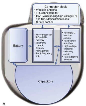
The essential elements and principles of these components are detailed in this section. A schematic diagram showing these components is shown in Figure 84-1, A.
Batteries
ICD batteries have several requirements. These include, among others, availability of different voltage levels for pacing and monitoring functions versus defibrillation therapy, substantial longevity, mechanical and electrical durability, and patient safety. In typical ICD batteries, a lithium metal plate serves as the anode, and a silver vanadium oxide plate serves as the cathode (see Figure 84-1). The electrolyte is a solution of a lithium compound in a highly conductive organic solvent or solvents. Multiple layers of the anode and cathode are present in an ICD battery. The battery’s electrode and electrolyte are contained within a hermetically sealed metal case. These two elements immediately interact, and the electrons released from the lithium anode enter the external device circuit. The cathode accepts electrons from the external circuit. Progressive and uncontrolled charge buildup on the anode and cathode is prevented by the ionic nature of the electrolyte.
High-Voltage Shock Therapy
High-voltage capacitors store and deliver the high-energy pulses needed to cardiovert and defibrillate tachyarrhythmias (see Figure 84-1). Capacitors, in essence, consist of two conductors, insulated from each other by a di-electric material, that charge via a charging circuit connected to the battery. During charging, these conductors assume equal but opposite charges that discharge through the lead system to deliver a high-voltage, high-energy shock. Voltage delivered in the shock decays in an exponential waveform, and the actual delivered energy is usually less than the stored energy. Thus measures of both are available for ICD devices. Capacitor size is a major determinant of overall ICD generator size. High-energy density minimizes capacitor size. ICD capacitors use aluminum or tantalum electrode either as foils, which are etched to increase surface area, or as porous pellets. Tantalum capacitors have a smaller size but a greater mass.
Sense Amplifiers and Sensing Circuits
Accurate sensing of input signals and their analysis are important challenges for ICD devices. Near-field and far-field signals are often present in the signal presented by the lead or leads connected to the generator. The amplitude of the signal is measured against a comparator set by the sensing threshold value. However, the tachycardia and fibrillation signal can be highly variable with respect to amplitude on a beat-to-beat basis, along with changing slew rates and morphology. To address this challenge, an important technical feature of ICD sensing circuits is the automatic adjusting signal amplifier “autogain” feature. This feature compensates for variable amplitudes of electrograms during the arrhythmia. The signal amplitude can vary as much as 10 times during a single episode of ventricular fibrillation (VF). Variability in electrocardiogram (ECG) amplitude during VF has also been observed to be a cause for redetection failure.5 The sense amplifier must be able to respond to the widely varying cardiac signals and does so by changing the sensing threshold on a beat-to-beat basis. It is initially set to a fraction of the signal amplitude, and then the threshold decays over time, depending on programming on the threshold and delay. Raising gain for low-amplitude signals can increase oversensing, resulting in oversensing of T waves and “double counting” of fragmented potentials or skeletal myopotentials, leading to inaccurate detection. The autogain feature adjusts sensitivity on the basis of the amplitude of recently sensed signals. The autogain feature of some devices increases sensitivity when a rapid rhythm is detected to sense VF. It also increases sensitivity during bradycardia pacing so that low-amplitude signals from VF will not be interpreted as bradycardia.
Developments in Device Material Technology
Implantable Cardioverter-Defibrillators for Ventricular Defibrillation
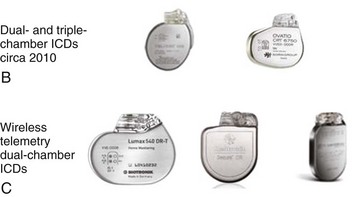
Technological developments in the original ICD device have now improved its functionality. The transition from an epicardial lead system to wholly nonthoracotomy placement occurred in 1987, with the inclusion of a left extra-thoracic patch lead that permitted a larger electrode surface area combined with a new left-to-right shock current vector for successful endocardial defibrillation.6 In the original version, a three-electrode configuration permitted two simultaneous shock vectors, left-to-right and right-to-left, for bi-directional current delivery to improve defibrillation thresholds (DFTs). Refinements to both generator and lead systems in the past decade have simplified the implementation of endocardial defibrillation with wholly transvenous implantation. This included use of a biphasic shock waveform as the standard defibrillation shock waveform, which helped reduce defibrillation energy and reduced the need for multiple electrodes for optimal energy transfer to the myocardium.7 New lead configurations have permitted reliable transvenous defibrillation within the maximal leading edge shock voltage (750 to 800 V), available in most ICD generators, in more than 98% of all patients.8 The device can now serve as an integral component of the shock energy delivery system—becoming an active pectoral lead replacing left thoracic patch electrode insertion in the original systems.7 ICD generator size has consistently been reduced, with device volumes now well under 40 cm3 (see Figure 84-1). Although sub-30-cm3 devices are a reality (e.g., the 29-cm3 Sorin Ovatio CRT ICD; Sorin Group, Milan, Italy), the trade-off between generator size and the surface area needed for optimal DFTs is now becoming an issue (see Figure 84-1). Wireless telemetry is now incorporated in three devices currently available in the United States (Biotronik Lumax [Berlin] Medtronic Secura series [Minneapolis, MN], and St Jude Current Promote RF [St Paul, MN]). Because of this feature, the header size increases with overall increase in generator volume (see Figure 84-1).
Single-Chamber Ventricular Implantable Cardioverter-Defibrillator Technology
Device Insertion
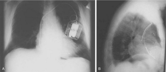
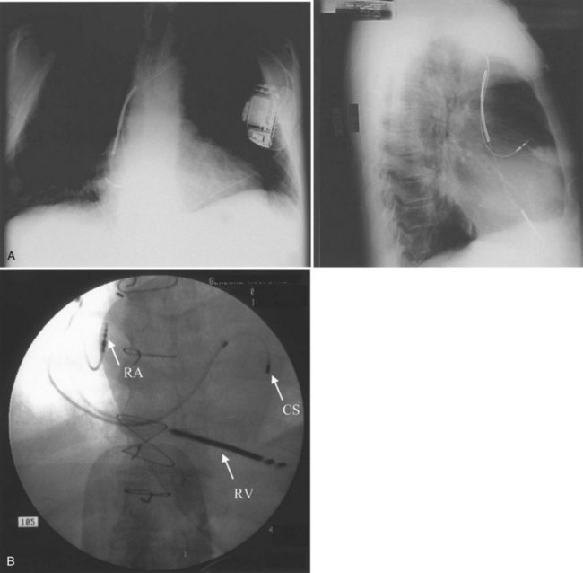
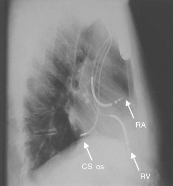
In its simplest iteration, the ICD device has capabilities for the detection of lethal ventricular tachyarrhythmias and permits ventricular pacing and monitoring of ventricular rhythms alone. This requires insertion of a single, combined ventricular pacing and defibrillation lead via cephalic or subclavian vein placement with a pectoral generator site—the generator being an active defibrillation shock electrode (Figure 84-2, A). The defibrillation lead includes a large surface area electrode in the right ventricle, integrated or true bipolar sensing, and an active or passive fixation mechanism.9 The shock current is transmitted between the right ventricular electrode and the generator, since a right-to-left shock vector reduces defibrillation threshold energy. Left-sided placement of the generator is therefore preferred, whenever feasible, although right-sided placement is possible. In studies on human DFTs with different lead configurations, the mean energy for defibrillation varies with electrode configuration and location. In addition, the electrode surface area is a critical determinant of current and voltage requirements for defibrillation by virtue of its effects on the electrode-myocardium interface and shock energy vector. Thus DFTs vary in inverse proportion to the electrode surface area, with defined boundaries for such effects in either direction. The addition of a third SVC or right atrial electrode permitted bi-directional shock vectors, which may reduce mean DFTs by 10% to 20%, as shown in some studies, and by larger increments in individual patients. Initially, a second superior venocaval electrode was used for this purpose (see Figure 84-2, B), but now dual-electrode catheters with variable spacing of the two defibrillation coils obviate the need for an additional lead. Similarly, reversal of shock polarity may not reduce DFTs in population studies but can alter thresholds in specific patients. Both these maneuvers are of value in patients with high DFTs. Several endocardial defibrillation leads routinely include two defibrillation electrodes for right ventricular and SVC locations, resulting in a bi-directional shock configuration. Reduction in generator size for cosmetic acceptability and implant simplicity may require attention to optimal generator location for successful and low DFTs. In our early studies on left-sided electrode location for defibrillation, the lowest DFTs were achieved with left axillary locations in the anterior to midaxillary line in the vicinity of the fourth intercostal space, with slightly higher values in the left infraclavicular location in the second intercostal space.10 Currently, this latter location is most commonly used for generator placement. Axillary locations can reduce DFTs, but are not widely used because of arm movement issues; however, they remain an option in some patients. Highest thresholds are obtained with an apical placement in the left midclavicular line at the fourth or fifth intercostal space. Thus the thoracic site of placement or relocation of a generator can have an impact on DFTs, which should be considered by an implanting physician.
Tachyarrhythmia Detection
Ventricular rhythm detection in these systems is based on the ventricular electrogram rate, regularity, morphology, and patterns of electrogram interval changes. Initial detection in all devices is based on absolute ventricular rate, with most devices allowing up to three zones for distinguishing different tachyarrhythmias. In general, a minimum of two-zone programming is usually performed for distinguishing monomorphic ventricular tachycardia (VT) from VF. When empiric programming is sought, we prefer to establish three zones for “slow” VT, “fast” monomorphic ventricular tachyarrhythmias, and VF, as illustrated in Figure 84-3.11–12 Such distinction is useful for both clinical and therapeutic purposes. The slowest zone is usually associated with nonsyncopal rhythms, which are often responsive to anti-tachycardia pacing. The second zone has symptomatic rhythms, but early anti-tachycardia pacing or cardioversion with a lower energy shock with rapid charge times may abort the syncope. Very rapid anti-tachycardia pacing can be considered in this zone. Finally, ventricular fibrillation is usually syncopal in many patients and requires a highly effective shock for immediate termination based on threshold determination. Although nominal detection rate values are provided by manufacturers, it is important to individualize these values on the basis of the patient’s sinus rhythm mechanism, its chronotropic competence, exercise response and activity level of the patient, and the presence of coexisting supraventricular tachyarrhythmias and their ventricular rates. It is generally preferable to ensure a difference of 15 to 20 beats/min between the maximal sinus rate or supraventricular arrhythmia rate and the initial threshold rate for VT detection, provided the latter arrhythmia rate falls above this value by at least 10 to 15 beats/min. If this level of distinction is not possible on the basis of rate alone, and overlapping rates are present between supraventricular tachycardias (SVTs) and VTs, other algorithms are available in most devices to help identify the arrhythmia.
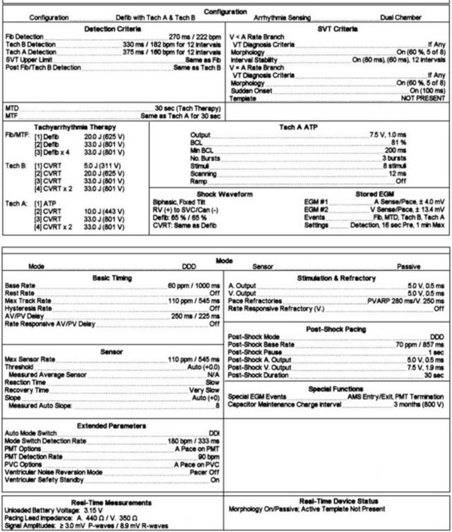
All devices offer sudden onset criteria, which identify an abrupt cycle length change in the ventricular cycle, to discriminate a pathologic tachycardia from sinus tachycardia. In addition, electrogram morphology in supraventricular and ventricular tachyarrhythmias may be matched to the sinus rhythm template. In the absence of intraventricular conduction abnormalities, supraventricular rhythms can often be identified by similar ventricular electrogram morphology. The duration of the ventricular electrogram as a discriminating factor, although used often, is less valuable. Ventricular electrogram duration may increase in ventricular tachyarrhythmias because of slower intraventricular conduction without the use of the specialized conduction system (Figure 84-4). However, few systematic data validate this belief, and “narrow” complex VTs are surprisingly common. Most devices consider sustained high-rate events as ventricular in origin for patient safety and trigger a therapeutic strategy. In many patients, ventricular tachyarrhythmia rates can be variable, particularly with changing autonomic tone and antiarrhythmic drug therapy. Presentation with a monomorphic tachycardia rarely predicts subsequent freedom from VF. In fact, in clinical studies, the mortality and event rates in patients with hemodynamically “stable” VT were comparable with those in patients who had sustained a cardiac arrest.13
Device Therapies
Anti-tachycardia Pacing or Cardioversion
Tachyarrhythmia and bradyarrhythmia therapies are available in these devices. Ventricular demand pacing with or without rate response is present. Ventricular pacing output can be altered for specific situations such as anti-tachycardia pacing or post-shock bradycardia pacing. Tachyarrhythmia therapies include anti-tachycardia pacing for termination of monomorphic VT, and low- and high-energy programmable shock therapies for cardioversion of VT and defibrillation of VF.4,15 Anti-tachycardia pacing is most effective in the termination of monomorphic VT, especially with rates below 180 beats/min, although individual episodes with rates above this may respond to this therapy.1,15–17 In slow VT, the excitable gap is large; therefore anti-tachycardia pacing can easily interrupt the tachycardia. When the tachycardia is fast, the excitable gap is shorter, and anti-tachycardia pacing interruption may be more difficult. Pacing termination of rapid VT is discussed below.
Several types of anti-tachycardia pacing are available in these devices. It is not uncommon for several attempts or different algorithms to be deployed during such efforts at tachycardia termination in an individual patient. Allowances for these repetitive efforts must include the hemodynamic stability of the patient during anti-tachycardia pacing programs. These algorithms include burst pacing, which may be rate adaptive or fixed rate, and low-energy cardioversion shocks (Figure 84-5). In rate-adaptive algorithms, the pacing rate is determined by the tachycardia rate and is generally a percentage of that rate. Commonly used adaptive algorithms use adaptive rates, which can vary from 95% to 70% of the tachycardia rate, for a given number of pacing stimuli.15 Most commonly used adaptive rates for efficacy vary between 75% and 90% with 3 to 20 delivered pacing stimuli. Ramp pacing modes vary the intervals during a burst to an accelerating (positive) or decelerating (negative) ramp. Other algorithms use scanning programmed extrastimuli, usually on the basis of electrophysiology study (EPS) or ramp or burst pacing with terminal programmed scanning extrastimuli.18 In general, burst or ramp pacing, or variations thereof, provide the greatest likelihood of efficacy, especially if extensive EPS is not used for pace-termination windows and algorithms. Randomized comparative studies suggest similar efficacy for both modes.11
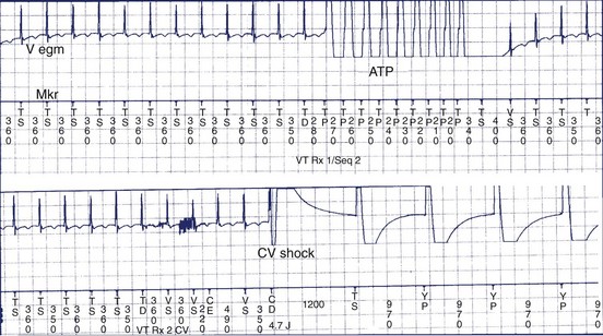
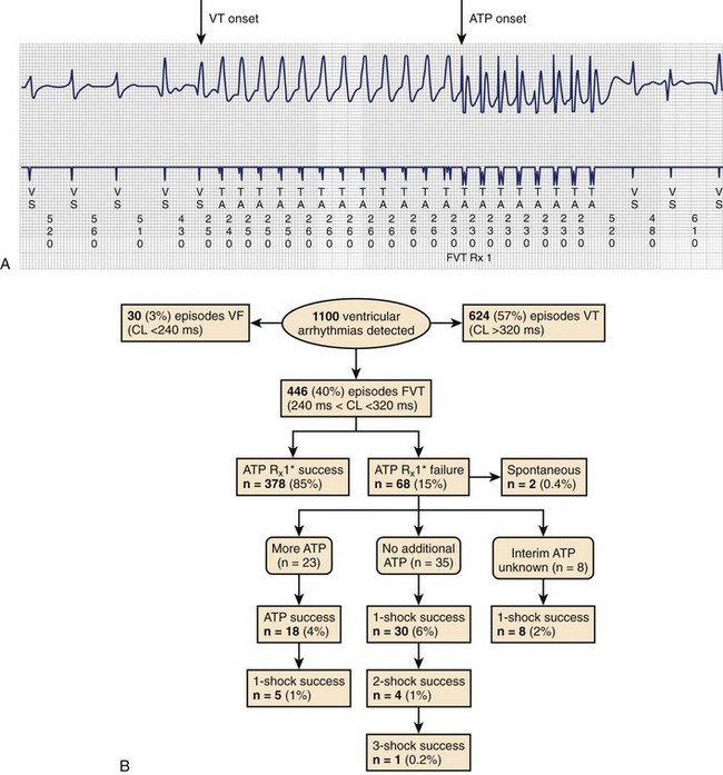
Clinical studies have documented a reduction in the need for defibrillator shocks with anti-tachycardia pacing from its early application to the present.18,19 The Pain Free 1 and 2 trials evaluated the use of anti-tachycardia pacing in rapid VT and its clinical impact.16,17 Anti-tachycardia pacing was performed with a predetermined adaptive pacing train at 91% of a rapid VT cycle for eight beats (Figure 84-6) to successfully terminate the episode (see Figure 84-6, A). In Pain Free 1, 32% of all VT events were in the rapid VT zone, whereas 58% were in the slow VT zone; 85% of all rapid VT events with a cycle length less than 320 ms were terminated by the initial pacing algorithm (see Figure 84-6, B), another 4% were terminated by subsequent algorithms, and only 10% of patients proceeded to shock therapy. A marked improvement was seen in quality of life measures of physical and mental functioning. These results indicate that anti-tachycardia pacing can be effective for treating fast VT and preventing painful shocks and secondary rehospitalizations. Multiple shocks for incessant VT have been shown to reduce battery longevity. Current-generation ICD devices provide anti-tachycardia pacing train delivery during charging.
The recent trend is a more intensified use of empirical ICD programming.18,19 However, these algorithms merit significant device testing to ensure efficacy. We prefer to establish a greater than 80% likelihood of efficacy for pace termination before final programming of the algorithm, particularly in slow VT. At a minimum, 10 episodes of induced tachycardia should be tested in the laboratory for pace termination; higher standards have been previously advocated.
Defibrillation Therapies and Threshold Testing
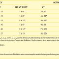
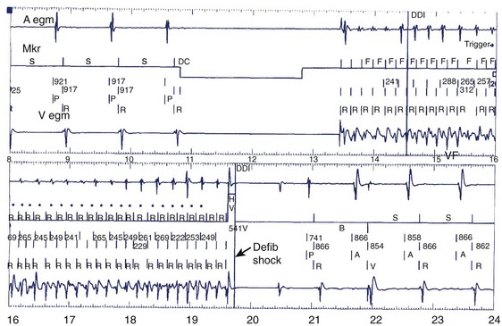
Initial defibrillation energy programming is based on the DFT. This threshold is not a fixed value and is a probabilistic value in an individual patient at a specific moment. The defibrillation efficacy curve has been well demonstrated in human and animal studies to be sigmoid in nature, with the threshold being at the superior but still rising end of the curve. The principles and mechanisms of defibrillation are discussed in Chapter 14. Thus the objective of reliable and reproducible defibrillation in a patient requires objective determination of defibrillation efficacy during testing and the use of initial shock energies that are highly likely to be successful. This mandates the use of energies at, or close to, this threshold. Repeated efficacy of the lowest successful energy is needed to place the shock near the threshold, with three successive or repeated successful terminations needed to place the shock energy at this level of efficacy. Another approach is to statistically predict the likelihood of success with a maximal energy shock and limit the testing. Thus two successful shocks at 10 J or less or a single successful shock at 5 J is highly likely to predict success with a 30-J shock. In unstable patients in whom testing is to be limited by clinical imperatives, knowledge of defibrillation protocols is invaluable in defining an optimal testing protocol. Step-down DFT testing is used in our laboratory commencing at the mean value for a particular electrode configuration to minimize the number of induced VF episodes. This is most often 10 J for left-sided pectoral devices and 15 J for right-sided implants (Figure 84-7).8 Induced VF is obtained by using the noninvasive induction sequences available in the device. The initial shock energy or voltage is tested and based on outcome when subsequent inductions are performed. If the initial shock is unsuccessful, rescue high-energy, device-based or external defibrillation should be used. After hemodynamic stability is restored and 3 to 5 minutes elapse, further testing is performed in step-down decrements if the initial shock was successful; step-up increments are used if it failed for the initial shock efficacy. Other techniques use a binary protocol with an up-down approach for minimizing shocks and arrhythmia episodes. Once the lowest successful shock energy or voltage is identified, we recommend two additional attempts to confirm reproducible efficacy. Three successful terminations at this level or three out of four such attempts place the shock at or above 90% of the DFT.
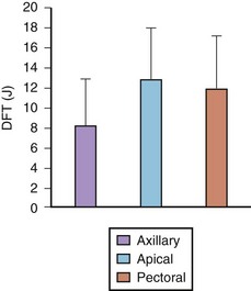
FIGURE 84-7 Defibrillation thresholds (DFT) with differing thoracic electrode locations.
(Modified from Saksena S, DeGroot P, Krol RB, et al: Low-energy endocardial defibrillation using an axillary or a pectoral thoracic electrode location, Circulation 88:2655–2560, 1993.)
When patient stability issues intrude and abort extensive testing, reproducibility of a single energy level is sought. In either instance, a 10-J safety margin is programmed above the successful shock energy to ensure efficacy. The second and subsequent defibrillation shocks can, and should, be programmed to maximal shock energy for the potential rise in defibrillation energy that is observed with prolonged VF events. This usually supervenes when such events exceed 30 seconds in clinical studies. Reversal of successive shock polarity may improve efficacy in some situations, although the optimal shock polarity should be determined at implant testing. An increasing amount of information suggests that DFT testing is not associated with improved outcomes.20–22 Significant controversy has been ignited with the suggestion that DFT testing is associated with a potentially greater implant risk.22 There clearly is a need to define the patients who would be at risk with such testing. Evidence suggests that DFT testing can be safely avoided in many patients but concerns exist, particularly for patients with high DFTs. With an increasing trend to limit implant testing, lack of knowledge of defibrillation energy requirements may compromise the ability to safely introduce new drugs or maintain confidence in the device’s ability to defibrillate when intercurrent clinical scenarios such as heart failure or ischemia potentially raise DFTs.
Device-Based Monitoring
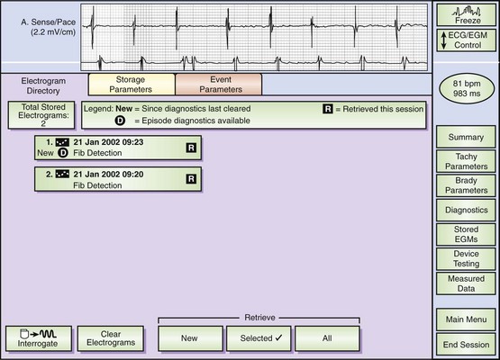
Monitoring and testing functions in these devices have improved ease of use and device performance and have provided more automated device-based testing with expanded capabilities, which include continuous arrhythmia detection and noninvasive EPS. Many of these features are present in current pacemakers and have been simply extended to the ICD. These include battery status, lead impedance measurement on a frequent (even daily) basis, pacing thresholds, and extent of pacing. Diurnal pacing rates, rate response, and hysteresis rates are present in many devices. Additional features specific to defibrillators include the capacitor charge time to maximal shock delivery. This was once a key manual test performed at follow-up, but now it can be automatically initiated by the device at prespecified intervals of time. Charge times in excess of 12 seconds merit close attention and frequent follow-up, and suggest the impending end of battery life. We routinely recommend battery replacement if charge times exceed 15 seconds because this prolonged interval permits longer arrhythmic episode continuation before intervention. This can approach intervals in which defibrillation energy requirements can rise, substantially increasing the likelihood of failure and also predisposing patients to syncope prior to intervention. Tachyarrhythmic events are logged with a time-and-date stamp and their duration recorded (Figure 84-8). In most devices, recorded ventricular electrograms are available for a segment of the event. Recording capabilities for such digitized graphics require substantial device memory, which has been rapidly expanding with more than 120 seconds available in some newer devices. These monitoring capabilities also contribute to substantial current drain on the battery and, if used indiscriminately, can limit longevity. During follow-up evaluations, the patient’s arrhythmia history since the last visit or even since implantation is readily available.
Device-Based Testing
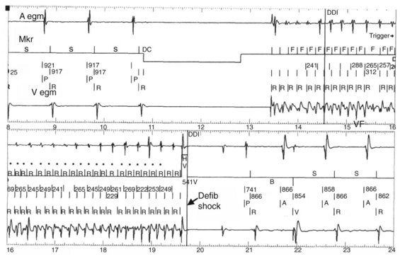
Noninvasive EPS has been available for device-based testing for tachycardia induction and termination in ICD devices. During such testing, noninvasive communication with the device is established by a hand-held wand and driven by a software-based external programmer. The present day ICD device can be temporarily programmed to a ventricular stimulation mode for VT induction. VF induction is achieved by using shocks delivered in the vulnerable period on the T wave during ventricular pacing, 50-Hz pacing bursts, or standard high-rate ventricular pacing bursts (Figure 84-9). This permits testing of the pre-programmed tachyarrhythmia detection algorithm and selected therapy for appropriate function of the device.
Tachycardia Detection in Implantable Cardioverter-Defibrillators
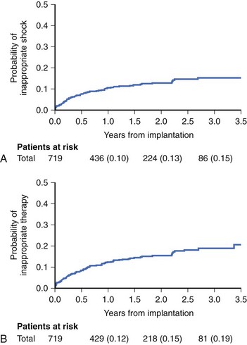
Reliable detection algorithms for arrhythmias are just as important as the circuitry in ICDs. The general idea is to deliver a life-saving shock when in doubt rather than withhold the shock. Current ICDs have improved detection algorithms but still deliver inappropriate shocks 10% to 40% of the time. In Multicenter Automatic Defibrillator Implantation Trial II (MADIT II), inappropriate shock therapy was delivered in 20% of patients by 3.5 years (Figure 84-10), and overall clinical trial experience suggests that this can comprise one third of all shocks.23
Another important technical feature of ICDs is the automatic adjusting signal amplifier autogain. This feature compensates for variable amplitudes of electrograms during arrhythmia. The signal amplitude can vary as much as 10 times during a single episode of VF. Variability in ECG amplitude during VF has also been observed to be a cause for redetection failure.5 Also, a high gain for low-amplitude signals can increase sensing and oversense T waves “double counting” skeletal myopotentials, leading to inaccurate detection. The autogain feature adjusts sensitivity on the basis of the amplitude of recently sensed signals. Autogain feature of some devices increases sensitivity when a rapid rhythm is detected or to sense VF. It also increases sensitivity during bradycardia pacing so that low-amplitude signals from VF will not be interpreted as bradycardia.
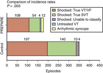
Although a variety of approaches have been used to improve the specificity of tachycardia detection and device therapy, a recent clinical trial—Primary Prevention Parameters Evaluation (PREPARE)—modified the detection time in an effort to reduce device therapies for nonsustained tachycardias in a primary prevention defibrillator population.24 No increase was observed in patient mortality with increased detection time to seconds. Figure 84-11 shows event rates of appropriate and inappropriate shock therapy in the study. A significant reduction in both shocks for VT and supraventricular tachyarrhythmias is observed, with a minimal increase in arrhythmic syncope events. A reduction in proportion of patients receiving all-cause shock therapy (from 16.9% to 8.5%) and shocks for ventricular tachyarrhythmias (from 9.4% to 5.4%) was seen. A significant improvement was observed in the morbidity index related to device-based therapy in the PREPARE patient cohort.
Dual-Chamber and Triple-Chamber Ventricular Implantable Cardioverter-Defibrillator Technology
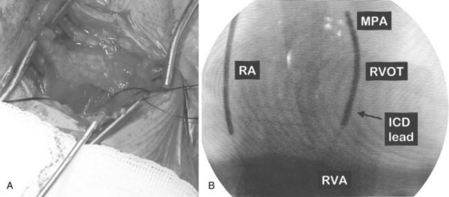
Conventional dual-chamber pacing has been available in ICD devices for more than 10 years, and their programmability has gradually expanded. These devices require the insertion of an additional bipolar atrial pacing lead in the right atrium, similar to a conventional pacemaker (Figure 84-12, A). The device header size is minimally enhanced with an additional port for this lead. Electrode spacing on this lead has been reduced to avoid far-field R-wave sensing, and lead placement in a high lateral right atrial location has been advised for the same reason. Inappropriate atrial lead placement can seriously impair the tachyarrhythmia functions of this device.
Triple-chamber pacing is now available with biventricular pacing ICDs (see Figure 84-12), which are discussed fully in Chapter 85 with indications and implantation techniques. These ICDs are devised to treat drug refractory congestive heart failure (CHF) populations with ventricular dyssynchrony.
Tachycardia discrimination in these devices now uses traditional rate-based detection algorithms in both chambers, overlaid with pattern analysis of atrial and ventricular electrogram relationships (see Figure 84-9). Rate detection alone can easily differentiate rapid and unrelated atrial activity such as that seen in AF or ectopic atrial tachycardia (AT) with varying block from ventricular tachyarrhythmias. Difficulties remain when AV relations are fixed and have identical rates.14 In such situations, VT with 1:1 retrograde atrial conduction is hard to differentiate from an atrial tachyarrhythmia with antegrade 1:1 conduction. This could include AT or atrial flutter (AFL) for 1:1 conduction. Rules for discrimination have been established in device logic and are highly individualized for each device. For example, the initial PR logic algorithm in the Medtronic Gem device series used a rule for the timing of the atrial event in the ventricular cycle, with the midpoint discriminating antegrade and retrograde atrial activations. This rule was subsequently discarded with the recognition that AV conduction intervals can vary and prolong substantially in very rapid atrial arrhythmias, reducing algorithm efficiency. In contrast, the PARAD algorithms in the Sorin devices examine the onset relationship of the atrium and the ventricle and note the chamber showing initial acceleration, which is then used as an important determinant of tachycardia origin. Whereas atrial triggers can initiate a ventricular tachyarrhythmia in an occasional patient, this algorithm has proved to be quite robust in clinical practice. Finally, the most recent devices provide retrieval of both atrial and ventricular electrograms on the basis of operator-selected parameters for arrhythmic episodes. These provide important discriminatory information with respect to device detection and therapy. More importantly, new device intervention–induced tachyarrhythmias are now more commonly detected, as are successive distinct arrhythmias in an individual patient (Figure 84-13).
Current indications for dual-chamber ICD insertion in patients with ventricular arrhythmias include standard indications for dual-chamber pacing such as sinus node dysfunction with conduction system disease or when AV nodal blocking drugs are concomitantly administered, in advanced AV block when physiological pacing is desired, or in patients with left ventricular dysfunction.4 They are particularly desirable in patients with coexisting atrial and ventricular tachyarrhythmias for discrimination of the two rhythms.
Dual-Chamber Atrioventricular Implantable Cardioverter-Defibrillator Technology
The first generation atrial defibrillation device has been replaced by a commercially available dual-chamber AV defibrillator as illustrated in Figure 84-13.25–29 The technology permits individualized atrial and ventricular anti-tachycardia therapies to be delivered, extending the device population beyond discrimination of coexisting atrial and ventricular tachyarrhythmias in the same patient.27–29 Initial studies have been conducted in patients with AF who may or may not have coexisting lethal ventricular tachyarrhythmias.27–29 Because the population pool of AF is very large and atrial cardioversion is a commonly used procedure, the chances of this technology being available in a hybrid therapy format is likely to increase. Stand-alone atrial defibrillation devices, which have been evaluated in a prototype form, have significant limitations in clinical capability, application, and safety and have been largely discarded.29 Dual-chamber defibrillators are approved for use in patients with drug-refractory and symptomatic AF and in patients with coexisting symptomatic atrial and ventricular tachyarrhythmias.
The atrial channel now permits classification and zone-based therapy of atrial tachyarrhythmias in a manner quite similar to the single-chamber ventricular ICD. It requires insertion of an additional atrial defibrillation electrode. This electrode can be mounted on separate and distinct pacing and defibrillation leads placed in the right atrium and extending into the superior vena cava (SVC) for pacing, detection, and shock delivery. Alternatively, the SVC electrode on a conventional ventricular defibrillation lead can provide the atrial defibrillation electrode and a conventional pacing lead used in the atrium. The use of coronary sinus defibrillation leads was widely advocated initially because of modestly lower DFTs.18–26 However, the reduction in thresholds had few clinical advantages, except in the management of the patient with high atrial DFTs.26 Energy thresholds were still too high for patient tolerance for repeated use. Many clinical disadvantages with the existing technology have limited the use of this approach. These include difficult lead insertion, with prolonged procedure times, sensing, and pacing issues from the coronary sinus. The use of such leads can require highly specific and sophisticated algorithms to avoid cross-talk with the ventricular channel and pose significant risks in lead extraction. These issues become particularly important when the AF population has coexisting ventricular tachyarrhythmias.
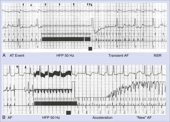
Atrial tachyarrhythmia detection is based on a two-zone rate stratification structure, with a monomorphic tachycardia zone for ATs and AFL categorization and a fibrillation detection zone. Cycle lengths in these two zones are selected on the basis of spontaneous or induced arrhythmias, and therapies are individualized for each zone. Anti-tachycardia pacing, using burst, ramp, or 50-Hz trains, is available in the tachycardia zone. The efficacy of the former two has been proved in prior experiences with anti-tachycardia atrial pacemakers and in laboratory testing.27 Burst pacing and ramp pacing have been effective in both intra-atrial re-entrant tachycardia and common AFL, with a lower efficacy rate in non–isthmus-dependent atypical AFL. Trains of 50 Hz for 1 to 4 seconds have been demonstrated to be effective—the latter arrhythmia with repetitive application, with efficacy rates of up to 60%.30 Back-up shock therapy is used if pacing therapies are ineffective with programmable shocks from 0.1 to 27 J. In the AF zone, 50-Hz pacing and shock therapy alone are available. The efficacy of 50-Hz trains in this zone is based on the categorization of very rapid monomorphic arrhythmias in the zone (Figure 84-14, A). It can also accelerate these rhythms into AF (see Figure 84-14, B). Established AF rarely responds to this modality. Atrial defibrillation shocks have similar principles of efficacy to ventricular defibrillation. A sigmoid defibrillation efficacy curve exists and thresholds vary widely with lead configuration. Inclusion of a coronary sinus electrode with a right atrial to coronary sinus vector provides lower thresholds compared with right-sided shocks using right atrial to right ventricle, or SVC to right ventricle, or configurations with a can or left pectoral electrode.31
In clinical studies, reliable atrial defibrillation has been obtained with shock energies of up to 27 J with the Medtronic Jewel AF device.27–29 Newer iterations of these devices include pacing prevention algorithms such as continuous atrial pacing for AF prevention. Enhanced monitoring capabilities of these devices include atrial and ventricular arrhythmia detection and categorization and electrogram detection in either chamber as programmed. Noninvasive electrophysiological stimulation is available in both the atrium and the ventricle. This permits testing of detection and therapies for both atrial and ventricular tachyarrhythmias. Finally, a handheld patient activator is available for delivery of shock therapy on demand by the patient or the physician. This device can activate shock therapy as programmed by physician prescription. Thus symptoms and duration of AF as determined by the user can be used in deciding cardioversion shock delivery.
Implantation of Implantable Cardioverter-Defibrillator Systems
The first generation of ICD systems used epicardial leads placed surgically via a transthoracic approach.32 In 1988, the first nonthoracotomy implantation involving transvenous leads and a submuscular patch was described.6 This permitted a right-to-left shock vector with successful defibrillation using monophasic shock waveforms. Further technologic advances in the last decade resulted in the use of biphasic shock waveforms in conjunction with endocardial defibrillation leads.33 This further reduced the energy requirements for defibrillation, allowing smaller sized pulse generators. The reduction in generator size, coupled with the replacement of patch leads with active generator can electrodes, permitted pectoral rather than abdominal implantation of ICD systems. The use of the epicardial approach is now limited to very few patients such as those with complex congenital heart lesions that do not permit transvenous lead placement or patients who lack vascular access required for lead placement. Even in patients undergoing routine cardiac surgery for any other indication, a postoperative transvenous implantation is preferred over intraoperative epicardial device placement. This is a result of the superior lead performance and durability associated with transvenous leads. The following section will provide a detailed description of the transvenous implantation technique. Epicardial placement techniques are briefly summarized, but the reader is referred elsewhere for a more detailed description of that procedure.33
Implantation Facility
Implantation of internal defibrillators requires a dedicated team consisting of an implanting physician (either surgeon or electrophysiologist), a fully trained electrophysiologist (if not the implanting physician), surgical nursing support, and technical support staff for ICD implantation and testing. At the present time, defibrillator system implantations are performed either in the operating room or in properly equipped electrophysiology or catheterization suites.34,35 Limited data suggest that no significant differences exist in complication rates between procedures performed in the operating room environment and in the electrophysiology laboratory.36 Regardless of the site, the implanting location should be equipped with general anesthesia capabilities, appropriate air filtering, surgical scrub areas, surgical sterilization and lighting, and high-quality fluoroscopy. Electrocardiographic and hemodynamic equipment permitting arterial pressure monitoring and intracardiac signal recording should be available in the suite as necessary. ICD procedures should be performed in hospitals with electrophysiology programs and rapid access to cardiac surgical services to be able to respond to the potential complications of the procedure.
Implantation Technique
Single-Chamber Ventricular Implantable Cardioverter-Defibrillator Implantation
ICD implantations are generally performed in the left pre-pectoral area to establish a left-to-right defibrillation shock vector. The generator is placed in a pre-pectoral pocket, and the leads are inserted transvenously from the cephalic veins, the subclavian veins, or both. With standard sterile technique, a pre-pectoral incision is performed suitable for cephalic or subclavian access (Figure 84-15, A). The initial incision is usually below the clavicle. The right pectoral region may be used in selected left-handed patients or if local abnormalities, infection, or venous access preclude using the standard technique. Transvenous lead insertion is then performed via either the cephalic route or the subclavian route, as described below.
The cephalic vein access for transvenous lead insertion is preferred over subclavian vein puncture because the latter can be associated acutely with a small risk of pneumothorax and arterial complications and in the long term with subclavian crush injury to the leads.37 Subclavian crush occurs when leads inserted via the subclavian vein are trapped within the costoclavicular complex or under the subclavius muscle. This phenomenon, which is almost never seen with the cephalic vein access, is more common with large-diameter defibrillating electrodes than with pacemaker leads.37 Dissection in the delto-pectoral groove is used to isolate the cephalic vein. The vein is controlled proximally and distally to the site of venous entry with ligatures. The vein is opened with a small incision. The pacing and defibrillator electrodes are then introduced and advanced via the subclavian vein into the right side of the heart into the pulmonary artery under fluoroscopic guidance (see Figure 84-15, B). The lead is withdrawn and fixed in the right ventricular apex. If the cephalic vein or the venous valves do not allow lead insertion, a guidewire can be passed into the right atrium. A split-sheath introducer is advanced over the wire permitting lead insertion. Ong and Barold described a modified cephalic vein guidewire technique for the introduction of one or more electrodes.38 In this technique, insertion of the guidewire into the cephalic vein is followed by insertion of the introducer and invagination into extra-thoracic segment of the subclavian vein with sacrifice of the cephalic vein.
If a subclavian puncture is required for the placement of the lead, it should be performed as far lateral as possible to minimize the risks of subclavian crush syndrome (Figure 84-16).39 Before vein puncture, the patient is placed in a Trendelenburg position, thus distending the vein, facilitating puncture, and avoiding air embolism. Fluoroscopy, with or without contrast venography using peripheral injection of 20 to 30 mL of contrast, can assist in localizing the vein.40 In rare instances, when both the cephalic and subclavian venous accesses cannot be obtained, the internal jugular, external jugular, or the axillary vein can be used. These alternative approaches require dissection that is more extensive and lead tunneling to reach the pectoral pocket.
Pacing and defibrillator leads are of larger diameters (approximately 9 Fr) and greater stiffness than pacemaker leads. Downsizing of lead diameters has occurred in the past few years with varying degrees of change in lead performance. The 7-Fr Medtronic Sprint Fidelis lead was associated with an increased incidence of lead fracture, especially at the tip, and has been discontinued (see Chapter 85 for more details). The 7-Fr St Jude pacing and defibrillation Durata lead model 7020 has had acceptable survival rates in the initial years of its introduction. Great care must be taken to avoid damage to the leads as well as the surrounding vascular structures during lead insertion. A curved stylet is inserted into the lead, and the lead is carefully advanced across the tricuspid valve into the right ventricular outflow tract and the pulmonary artery. Retracting the stylet to soften the lead tip can facilitate crossing of the tricuspid valve. The curved stylet is replaced with a straight stylet, and the lead is slowly withdrawn until it drops down toward the right ventricular apex. It is then gently advanced to the right ventricular apex, preferably with the stylet slightly withdrawn from the tip. The lead position chosen should place the defibrillation coil electrode in proximity to the inferior right ventricular myocardium. After optimal lead placement has been achieved, active fixation leads are anchored at the apex. The lead is then evaluated for stability with deep inspiration and after coughing. Pacing thresholds and diaphragmatic stimulation with pacing are assessed.
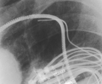
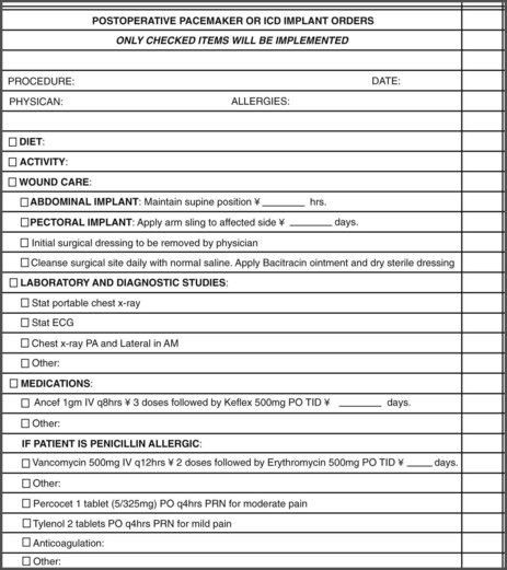
On the basis of the results of DFT testing, final programming of the device is then performed, and the pocket is closed. Postoperatively, the patient’s arm is placed in a sling, and an intravenous antibiotic is administered. A chest radiograph is obtained immediately after the implantation to define lead location and to exclude complications such as pneumothorax. Posteroanterior and lateral radiographs should be obtained before discharge for future reference. Patients are usually discharged within 24 hours of implantation. Predischarge ICD testing is recommended for final programming for VT and VF detection and therapy. In addition, patients may undergo a device shock or pacing therapies to facilitate psychological adjustment to device function. Figure 84-17 illustrates a typical checklist of postoperative orders for patients after ICD implantation at our institution.
Dual-Chamber Atrioventricular Defibrillation Devices
These devices incorporate atrial pacing and defibrillation algorithms in patients with combined AF with VT, VF, or both. The atrial defibrillation shock is delivered via an atrial and ventricular defibrillation electrode. The atrial defibrillation coil is mounted on a combined atrial pacing and defibrillation lead (see Figure 84-11) or incorporated in the ventricular defibrillation lead, with a separate atrial pacing lead being inserted in the patient. Atrial defibrillation threshold testing can be performed analogous to ventricular defibrillation. Commonly used shock configurations are similar to ventricular defibrillation, with a coronary sinus electrode being used on rare occasions. Insertion techniques are similar to those of dual-chamber ICD leads. The atrial defibrillation coil is usually located in the SVC or the high right atrium. It is important to maximize atrial sensitivity during device testing to accurately detect AF. This is best accomplished by reducing atrial sensitivity to 0.3 mV. These devices are infrequently used in patients with AF alone but are more useful in patients with both AF and ventricular tachyarrhythmias.
Postoperative Management
After device insertion, device behavior and limitations on specific physical activity should be reviewed with the patient. Immobilization of the ipsilateral arm in a sling for a short period after implantation is desirable. Prolonged immobilization can affect shoulder range of motion. Recent guidelines recommend restrictions on driving for secondary prevention ICD indications for a minimum of 3 months and preferably 6 months to determine pattern of recurrent VT or VF events.39 Patients with primary prevention implants are frequently allowed to drive, because the time to first event remains uncertain. Other limitations include magnetic resonance imaging, although methods for device shielding and devices with nonferrous metallic construction that will permit such imaging are being developed. Device interactions with electromagnetic sources, environmental issues, and antibiotic prophylaxis for device infections should also be discussed. ICD recipients should be encouraged to carry proper device identification documents at all times. Avoidance of prolonged exposure to electronic sensor systems should be emphasized. Patients receiving these devices can experience transient or sustained behavioral disturbances, including depression and anxiety.40,41 Education and psychological support before, during, and after ICD insertion are highly desirable and can improve the patient’s quality of life.42,43
Key References
Epstein AE, DiMarco JP, Ellenbogen KA, et al. ACC/AHA/HRS 2008 Guidelines for Device-Based Therapy of Cardiac Rhythm Abnormalities: American College of Cardiology/American Heart Association Task Force on Practice Guidelines Developed in Collaboration with the American Association for Thoracic Surgery and Society of Thoracic Surgeons. J Am Coll Cardiol. 2008;51:1-62.
Epstein AE, Miles WM, Benditt DM, et al. Personal and public safety issues related to arrhythmias that may affect consciousness: Implications for regulation and physician recommendations. Circulation. 1996;94:1147-1156.
Faust MM, Fraser J, Schurig LS, et al. Educational guidelines for the clinically associated professional in cardiac pacing and electrophysiology. Pacing Clin Electrophysiol. 1990;17:6.
Gillis AM, Leitch JW, Sheldon RS, et al. A prospective randomized comparison of autodecremental pacing to burst pacing in device therapy for chronic ventricular tachycardia secondary to coronary artery disease. Am J Cardiol. 1993;72:1146-1151.
Lau CP, Tse HF, Lok NS, et al. Initial clinical experience with an implantable human atrial defibrillator. Pacing Clin Electrophysiol. 1997;20(1 Pt 2):220-225.
Magney JE, Staplin DH, Flynn DM, et al. A new approach to percutaneous subclavian venipuncture to avoid lead fracture or central venous catheter occlusion. Pacing Clin Electrophysiol. 1993;16:2133.
Munsif AN, Saksena S, DeGroot P, et al. Low-energy endocardial defibrillation using dual, triple, and quadruple electrode systems. Am J Cardiol. 1997;79:1632-1639.
Neglia JJ, Krol RB, Giogorberedze I, et al. Evaluation of a programming algorithm for the third tachycardia zone in a fourth generation implantable cardioverter defibrillator. J Interv Card Electrophysiol. 1997;1:49-56.
Saksena S, for the PCD Investigator Group. Clinical outcome of patients with malignant ventricular tachyarrhythmias and a multiprogrammable cardioverter-defibrillator implanted with or without thoracotomy: An international multicenter study. J Am Coll Cardiol. 1994;23:1521-1530.
Saksena S, Chandran P, Shah Y, et al. Comparative efficacy of transvenous cardioversion and pacing in patients with sustained ventricular tachycardia: A prospective, randomized, crossover study. Circulation. 1985;72:153-160.
Saksena S, DeGroot P, Krol RB, et al. Low-energy endocardial defibrillation using an axillary or a pectoral thoracic electrode location. Circulation. 1993;88:2655-2660.
Saksena S, Parsonnet V. Implantation of an implantable cardioverter/defibrillator without thoracotomy using a triple electrode system. JAMA. 1988;259:69-72.
Saksena S, Prakash A, Mongeon, et al. Clinical efficacy and safety of atrial defibrillation using biphasic shocks and current nonthoracotomy endocardial lead configurations. Am J Cardiol. 1995;76:913-921.
Strickberger SA, Niebauer M, Ching Man K, et al. Comparison of implantation of nonthoracotomy defibrillators in the operating room versus electrophysiologic laboratory. Am Heart J. 1995;75:25.
Tullo NG, Saksena S, Krol RB, et al. Management of complications associated with a first-generation endocardial defibrillation lead system for implantable cardioverter-defibrillators. Am J Cardiol. 1990;66:411-415.
Wathen MS, DeGroot PJ, Sweeney MO, et al. Prospective randomized multicenter trial of empirical antitachycardia pacing versus shocks for spontaneous rapid ventricular tachycardia in patients with implantable cardioverter-defibrillators: Pacing Fast Ventricular Tachycardia Reduces Shock Therapies (PainFREE Rx II) trial results. Circulation. 2004;110:2591-2596.
Wathen MS, Sweeney MO, DeGroot PJ, et al. Shock reduction using antitachycardia pacing for spontaneous rapid ventricular tachycardia in patients with coronary artery disease. Circulation. 2001;104:796-801.
Watkins L, Mirowski M, Mower MM, et al. Implantation of the automatic defibrillator: The subxiphoid approach. Ann Thorac Surg. 1982;34:515.
Wilkoff BL, Williamson BD, Stern RS, et al. Strategic programming of detection and therapy parameters in implantable cardioverter-defibrillators reduces shocks in primary prevention patients: Results from the PREPARE (Primary Prevention Parameters Evaluation) study. J Am Coll Cardiol. 2008;52(7):541-550.
Winters WL, Achord JL, Boone AW, et al. American College of Cardiology/American Heart Association clinical competence statement on invasive electrophysiology studies, catheter ablation and cardioversion. J Am Coll Cardiol. 2000;36:1725.
1 Cobb LA, Baum RS, Alvarez H3rd, et al. Resuscitation from out-of-hospital ventricular fibrillation: 4 years follow-up. Circulation. 1975;52:223.
2 Lehmann MH, Steinman RT, Schuger CD, et al. The automatic implantable cardioverter defibrillator as the treatment modality of choice for survivors of cardiac arrest unrelated to acute myocardial infarction. Am J Cardiol. 1998;62:803.
3 Myerberg RH, Castellanos A. Evolution, evaluation and efficacy of the implantable cardioverter defibrillator technology. Circulation. 1992;86:691.
4 Epstein AE, DiMarco JP, Ellenbogen KA, et al. ACC/AHA/HRS 2008 Guidelines for Device-Based Therapy of Cardiac Rhythm Abnormalities: American College of Cardiology/American Heart Association Task Force on Practice Guidelines Developed in Collaboration with the American Association for Thoracic Surgery and Society of Thoracic Surgeons. J Am Coll Cardiol. 2008;51:1-62.
5 Tullo NG, Saksena S, Krol RB, et al. Management of complications associated with a first-generation endocardial defibrillation lead system for implantable cardioverter-defibrillators. Am J Cardiol. 1990;66:411-415.
6 Saksena S, Parsonnet V. Implantation of an implantable cardioverter/defibrillator without thoracotomy using a triple electrode system. JAMA. 1988;259:69-72.
7 Saksena S, An H. Clinical efficacy of dual electrode systems for endocardial cardioversion of ventricular tachycardia: A prospective randomized crossover trial. Am Heart J. 1990;119:15-22.
8 Munsif AN, Saksena S, DeGroot P, et al. Low-energy endocardial defibrillation using dual, triple, and quadruple electrode systems. Am J Cardiol. 1997;79:1632-1639.
9 Saksena S, An H, Mehra R, DeGroot P, et al. Prospective comparison of biphasic and monophasic shocks for implantable cardioverter-defibrillators using endocardial leads. Am J Cardiol. 1992;70:304-310.
10 Saksena S, DeGroot P, Krol RB, et al. Low-energy endocardial defibrillation using an axillary or a pectoral thoracic electrode location. Circulation. 1993;88:2655-2660.
11 Saksena S, Chandran P, Shah Y, et al. Comparative efficacy of transvenous cardioversion and pacing in patients with sustained ventricular tachycardia: A prospective, randomized, crossover study. Circulation. 1985;72:153-160.
12 Neglia JJ, Krol RB, Giogorberedze I, et al. Evaluation of a programming algorithm for the third tachycardia zone in a fourth generation implantable cardioverter defibrillator. J Interv Card Electrophysiol. 1997;1:49-56.
13 Raitt MH, Renfroe EG, Epstein AE, et alThe AVID Investigators. Ventricular tachycardia is not a benign rhythm: Insights from the Antiarrhythmics Versus Implantable Defibrillators (AVID) Registry. Circulation. 2001;103:244-252.
14 Saksena S, for the PCD Investigator Group. Clinical outcome of patients with malignant ventricular tachyarrhythmias and a multiprogrammable cardioverter-defibrillator implanted with or without thoracotomy: An international multicenter study. J Am Coll Cardiol. 1994;23:1521-1530.
15 Lindsay BD, Saksena S, Rothbart ST, et al. Prospective evaluation of a sequential pacing and high energy bidirectional shock algorithm for transvenous cardioversion in patients with ventricular tachycardia. Circulation. 1987;76:601-609.
16 Wathen MS, Sweeney MO, DeGroot PJ, et al. Shock reduction using antitachycardia pacing for spontaneous rapid ventricular tachycardia in patients with coronary artery disease. Circulation. 2001;104:796-801.
17 Wathen MS, DeGroot PJ, Sweeney MO, et al. Prospective randomized multicenter trial of empirical antitachycardia pacing versus shocks for spontaneous rapid ventricular tachycardia in patients with implantable cardioverter-defibrillators: Pacing Fast Ventricular Tachycardia Reduces Shock Therapies (PainFREE Rx II) trial results. Circulation. 2004;110:2591-2596.
18 Gillis AM, Leitch JW, Sheldon RS, et al. A prospective randomized comparison of autodecremental pacing to burst pacing in device therapy for chronic ventricular tachycardia secondary to coronary artery disease. Am J Cardiol. 1993;72:1146-1151.
19 Sullivan RM, Russo AM, Berg C, et al. Arrhythmia rate distribution and tachyarrhythmia therapy in an ICD population: Results from the INTRINSIC RV Trial. Heart Rhythm. 2001. e-Pub ahead of print
20 Blatt JA, Poole JE, Johnson GW, et al. No benefit from defibrillation threshold testing in the SCD-HeFT (Sudden Cardiac Death in Heart Failure Trial). J Am Coll Cardiol. 2008;52:551-556.
21 Bianchi S, Ricci RP, Biscione F, et al. Primary prevention implantation of cardioverter defibrillator without defibrillation threshold testing: 2-year follow-up. Pacing Clin Electrophysiol. 2009;32(5):573-578.
22 Birnie D, Tung S, Simpson C, et al. Complications associated with defibrillation threshold testing: The Canadian experience. Heart Rhythm. 2008;5(3):387-390.
23 Daubert JP, Zareba W, Cannom DS, et al. Inappropriate implantable cardioverter-defibrillator shocks in MADIT II: Frequency, mechanisms, predictors, and survival impact. J Am Coll Cardiol. 2008;51:1357.
24 Wilkoff BL, Williamson BD, Stern RS, et al. Strategic programming of detection and therapy parameters in implantable cardioverter-defibrillators reduces shocks in primary prevention patients: Results from the PREPARE (Primary Prevention Parameters Evaluation) study. J Am Coll Cardiol. 2008;52(7):541-550.
25 Lau CP, Tse HF, Lok NS, et al. Initial clinical experience with an implantable human atrial defibrillator. Pacing Clin Electrophysiol. 1997;20(1 Pt 2):220-225.
26 Saksena S, Prakash A, Mongeon, et al. Clinical efficacy and safety of atrial defibrillation using biphasic shocks and current nonthoracotomy endocardial lead configurations. Am J Cardiol. 1995;76:913-921.
27 Adler SW, Wolpert C, Warmann E, et althe Worldwide Jewel AF Investigators. Atrial therapies reduce atrial arrhythmia burden in defibrillator patients. Circulation. 2001;104:1023-1028.
28 Swerdlow C, Schls W, Dijkmann B, et alThe Worldwide Jewel AF investigators. Detection of atrial fibrillation and flutter by a dual-chamber implantable cardioverter-defibrillator. Circulation. 2000;101:878.
29 Timmermans C, Tavenier R, and the Worldwide Metrix Investigators. Ambulatory use of the Metrix automatic implantable atrial defibrillator to treat episodes of atrial fibrillation. PACE. 1998;21:811.
30 Giorgberidze I, Saksena S, Mongeon L, et al. Effects of high-frequency atrial pacing in atypical atrial flutter and atrial fibrillation. J Intervent Card Electrophysiol. 1997;1:111.
31 Cooper R, Smith W, Ideker RE. Internal cardioversion of atrial fibrillation: Marked reduction in defibrillation threshold with dual current pathways. Circulation. 1997;96:2693-2700.
32 Watkins L, Mirowski M, Mower MM, et al. Implantation of the automatic defibrillator: The subxiphoid approach. Ann Thorac Surg. 1982;34:515.
33 Trappe H, Pfitzner P, Heintze J, et al. Cardioverter-defibrillator implantation in the catheterization laboratory: Initial experience in 46 patients. Am Heart J. 129(259), 1995.
34 Strickberger SA, Niebauer M, Ching Man K, et al. Comparison of implantation of nonthoracotomy defibrillators in the operating room versus electrophysiologic laboratory. Am Heart J. 1995;75:25.
35 Magney JE, Flynn DM, Parsons JA, et al. Anatomical mechanisms explaining damage to pacemaker leads, defibrillator leads, and failure of central venous catheters adjacent to the sternoclavicular joint. Pacing Clin Electrophysiol. 1993;16:445.
36 Ong LS, Barold SS, Lederman M, et al. Cephalic vein guidewire technique for implantation of permanent pacemakers. Am Heart J. 1987;114(4 Pt 1):753.
37 Magney JE, Staplin DH, Flynn DM, et al. A new approach to percutaneous subclavian venipuncture to avoid lead fracture or central venous catheter occlusion. Pacing Clin Electrophysiol. 1993;16:2133.
38 Higano ST, Hayes DL, Spittell PC. Facilitation of the subclavian introducer technique with contrast venography. Pacing Clin Electrophysiol. 1990;13:681.
39 Epstein AE, Miles WM, Benditt DM, et al. Personal and public safety issues related to arrhythmias that may affect consciousness: Implications for regulation and physician recommendations. Circulation. 1996;94:1147-1156.
40 Vlay SC, Olson LC, Fricchione GL, et al. Anxiety and anger in patients with ventricular tachyarrhythmias: Responses after automatic internal cardioverter-defibrillator implantation. Pacing Clin Electrophysiol. 1989;12:366.
41 Luderitz B, Jung W, Deister A, et al. Patient acceptance ofthe implantable-cardioverter defibrillator in ventricular tachyarrhythmias. Pacing Clin Electrophysiol. 1993;16:1815.
42 Winters WL, Achord JL, Boone AW, et al. American College of Cardiology/American Heart Association clinical competence statement on invasive electrophysiology studies, catheter ablation and cardioversion. J Am Coll Cardiol. 2000;36:1725.
43 Faust MM, Fraser J, Schurig LS, et al. Educational guidelines for the clinically associated professional in cardiac pacing and electrophysiology. Pacing Clin Electrophysiol. 1990;17:6.