11 Immobilization and Simulation
For radiobiologic reasons, the radiation dose is delivered in single or multiple daily fractions over a period of several weeks.1 During radiation therapy, it is important to make sure that the patient is treated in a reproducible manner on a day-to-day basis and that the same volume is irradiated during each fraction. Particularly with modern conformal techniques,2,3 in which the planned isodose line tightly surrounds the target volume, a mismatch between the planned dose distribution and the delivered dose may cause an underdosage to the target or overdosage to the surrounding normal tissues. This results in a suboptimal outcome for the patient. Furthermore, for treatment sites such as lung and liver, where larger margins are needed to account for respiratory motion, techniques such as deep inspiration breath hold (DIBH),4 robotic tracking, and respiratory gating (RG)5 are used to spare the normal tissues.
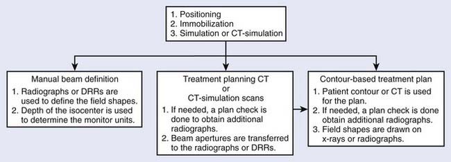
Radiotherapy simulation plays a crucial role in planning the strategy for the proper delivery of radiation dose. Important issues are decided during simulation, for example, how the patient will be positioned and immobilized and how the treatment beams will be directed. The flow chart in Fig. 11-1 shows some of the steps involved before treatment delivery. The simulation is carried out on a simulator or a virtual simulation is carried out on a CT simulator, and, to help in the patient’s alignment, the room also contains either wall-mounted or movable lasers.
The Conventional Simulator
The purpose of a radiation therapy simulator is to mimic the radiation treatment unit, but, instead of a high-energy therapy beam, it produces low-energy, diagnostic quality x-rays for imaging. Most of the preparation for the treatment is done at a therapy simulator, which saves valuable treatment machine time. A simulator has most of the functionality of a treatment unit; the relevant components of a modern therapy simulator are shown in Fig. 11-2. The simulator head contains a diagnostic x-ray tube mounted at one end of a rotating gantry. At the other end are a film cassette holder and a fluoroscopic unit or digital imaging device.
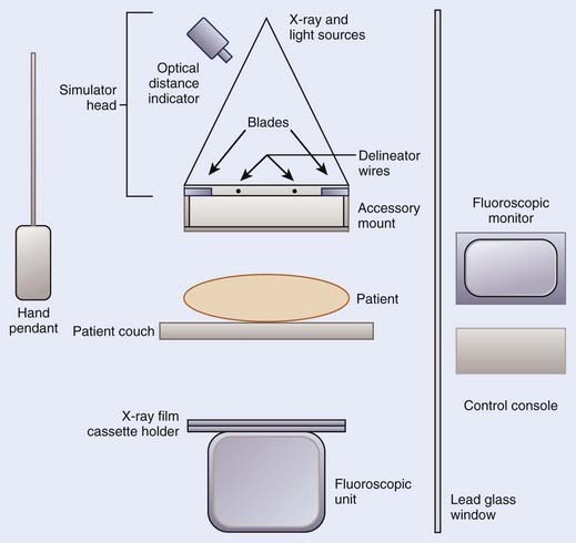
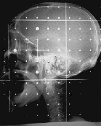
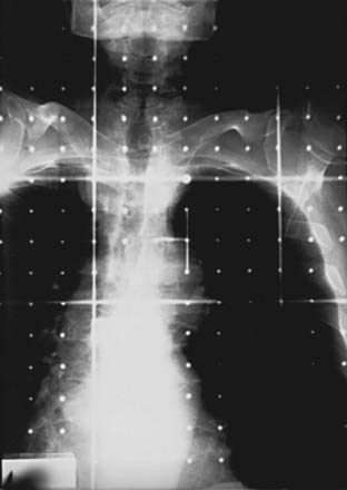
Housed in the simulator head is the collimator that has movable delineator (cross) wires and blades (jaws). On the simulator image, the delineator wires are projected as straight lines that define the field size. The blade positions determine the image size. A field localization light in the head projects the crosshairs and the delineator wires on the patient’s skin, which help in positioning the patient. The optical distance indicator measures the depth of the isocenter. The collimator includes an accessory mount that allows the treatment accessories, such as the block tray or the electron cones, to be mounted on the simulator. A gridded graticule tray with radiopaque markers provides a scale for measurement on the film. Fig. 11-3 shows a lateral head-and-neck radiograph on which the delineator wires, the crosshairs, and the graticule markers are projected. Fig. 11-4 is an anterior-posterior simulation film for a patient with lung cancer.
Computed Tomography Scanner and Spiral Computed Tomography Scanner
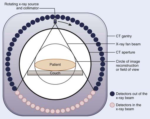
Since the first CT images obtained by Hounsfield,6 CT imaging has experienced rapid development. The major advancements have been in the area of image quality and scan time reduction. A fourth-generation CT scanner is shown schematically in Fig. 11-5. The x-ray tube and the collimator assembly rotate around the patient, and the intensities of the transmitted radiation reaching the detectors are recorded. Either a solid scintillation detector (bismuth germanate, cesium iodide, cadmium tungstate) array or a gas-filled (xenon or xenon-krypton) array is used for the detection. The transmission data are stored in the computer, and the image is reconstructed based on the attenuation information. The linear attenuation coefficients are converted into CT numbers, and the image is displayed on a video monitor. The CT numbers for the pixels are expressed in Hounsfield numbers and are related to linear attenuation coefficients:
where H is the CT number, µ is the linear attenuation coefficient for the pixel under analysis, and µw is the linear attenuation coefficient of water. The CT numbers in a scan range from −1000 to approximately +1000, with the CT number for water set at zero. A CT number of −1000 corresponds to air, and a CT number of +1000 is for very dense bone.
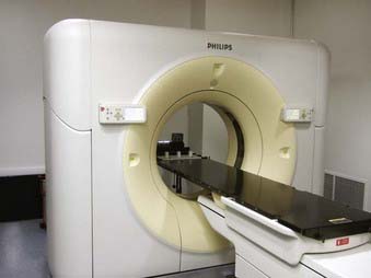
To obtain the volumetric data on a conventional CT scanner, after each scan the patient couch is translated to the new scan position. Because of the patient’s breathing and involuntary movement of the internal organs, motion artifacts are present unless special precautions are taken. In a spiral or helical CT scanner, the patient is transported through the gantry in synchrony with continuous data acquisition over a multitude of circular (360°) scans. Mathematical schemes7 have been developed to reconstruct axial scans that are similar to the scans obtained with a conventional scanner.8 On a spiral scanner, a volume or a subvolume can be scanned in a short time, on the order of 30 seconds. Another important development is the use of multisection imaging. The single narrow fan beam of x-rays is broadened into a cone beam, and each detector is replaced with a row of detectors (4 to 64). These detector rows are aligned parallel to the axis of the patient. These multidetector scanners are capable of imaging up to 64 sections of body simultaneously.9 Fig. 11-6 shows a multislice large bore (85 cm) scanner, used for CT simulation. The data for the whole study can be acquired during a single breath hold, resulting in images without interscan motion. From the diagnostic point of view, this is significant for locating small structures such as small pulmonary nodules, with which respiratory motion can cause detection problems.10 From the radiation therapy perspective, the advantages of the spiral CT scanner compared with a standard scanner are the ability to collect CT data with the patient in the immobilized treatment position within a shorter time frame and to create coronal and sagittal reconstructions with finer details.
The requirements for a therapy CT scan are different from those for a diagnostic scan.10,11 Some of the requirements are: (1) the patient should be scanned in the treatment position (the couch top should be flat, similar to a treatment couch; the physical CT aperture diameter and circle of reconstruction [field of view] should be large enough to accommodate the patient in the treatment position; if an immobilization device will be used during the treatment, the patient should be scanned immobilized, but the device should be made of materials that do not cause CT artifacts; and the anterior and lateral isocentric lines and other landmarks are marked on the skin by taping radiopaque catheters or lead beads); (2) CT scans should be of high quality so that the disease, tissue at risk, and surrounding normal tissues can be identified clearly; (3) particularly for three-dimensional (3D) treatment planning, a volume scan is required in order to delineate the treatment volume in three dimensions; in the region of treatment volume, a contiguous set with 5-mm spacing or smaller should be used to make sure that the small tumor extensions and normal structures are not missed (closely spaced scans also allow better image reconstruction); (4) anterior-posterior and lateral scout views should be obtained with the CT images indexed to these (these views are helpful in comparing CT data with conventional simulation radiographs); (5) the CT scanning should be completed in a short time period so that the patient remains adequately immobilized during the CT data collection; (6) for the treatment planning scans in the thoracic region, the patient should be scanned under shallow-breathing condition. Although the breathing introduces some motion artifacts in the images and the image quality may be degraded slightly, the scans represent the condition of the patient during treatment. However, there are interventional techniques, such as active breathing control, deep inspirational breath-hold and respiratory gating, can minimize the effect of respiratory motion, as discussed later.
Virtual Simulation
During conventional simulation the oncologist relies on the plain radiographs for designing the treatment ports. At times, even with the help of MRI, CT, and other diagnostic information, it is difficult to draw these ports accurately on the films. In the mid-1980s, Sherouse and colleagues12–14 introduced the term virtual simulation to describe a computer-based simulation process. They developed a software package that allowed the user to carry out simulation at a computer workstation instead of at a real simulator. The advantage of this method compared with plain radiographs is that the target volumes and anatomic structures, outlined on the CT scans, are used to make the decision about the position of the isocenter, field sizes, beam directions, and shielding blocks. CT scans provide better visualization of the disease and normal tissues, resulting in better target coverage and normal tissue shielding. The virtual simulator system has the ability to display and execute all the functions of a conventional radiotherapy machine, including gantry, couch, and collimator control.
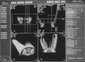
The CT data are obtained by scanning the patient in the immobilized treatment position. The CT scans are transferred to the planning system, and the skin, target, dose-limiting organs, and bony landmarks are contoured on the CT scans. The planner can view a 3D display of the patient model that consists of the skin, target, and other anatomic structures abstracted from the CT data. The contoured structures utilize different surface rendering and variable degree of transparencies to enhance the visualization. Fig. 11-7 shows a typical virtual simulator screen. Like a physical simulator, the virtual simulator allows the planner to adjust treatment parameters such as the gantry angle, field size, collimator angle, and so on. The beam’s-eye view (BEV) provides images that are similar to fluoroscopic images. The planner can select the treatment beam direction by watching projections of the target and surrounding structures in the BEV. The fields are then shaped by drawing the beam apertures using a mouse or other pointing device. At the end of the virtual simulation, digitally reconstructed radiographs (DRRs) are produced for each treatment field. A DRR15 is similar to a radiograph, but is designed by the computer based on the attenuation information derived from CT numbers in the original data set. The image quality of a DRR depends on the CT slice spacing—a smaller spacing results in a better DRR. The divergence of anatomic structures projected on a DRR is similar to that in the projection on a radiograph. The magnification of a DRR can be adjusted to match the simulation x-ray film. Along with the beam aperture and collimator, the target and other structures of interest are projected onto it. A list of beam, table parameters, and the templates for the beam modifiers are generated. Before the treatment, to verify the treatment ports, the localization port films can be compared directly with DRRs. Or, if the DRR quality is not good, the simulation radiographs in the treatment position can be taken and compared with the corresponding DRR. In many planning systems, the beam’s energy can be altered so that the DRR will look like a high-energy radiograph, making comparison to the port film simpler.
Computed Tomographic Simulator
The CT simulator is a whole-body CT scanner that is designed for radiation therapy simulation.16,17 It consists of three basic components: (1) a CT scanner, (2) an interactive workstation capable of virtual simulation, and (3) a mechanism for marking the beam portals on the patient’s skin. The patient is scanned in the treatment position and the CT images are transferred directly to virtual simulation workstation. The target volume and the relevant critical structures are outlined on the CT scans, the beam geometries are optimized, and DRRs are produced for the block definition and treatment verification.
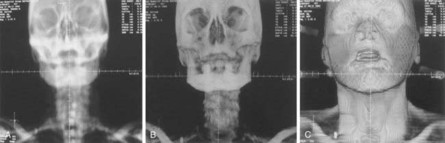
The advantages of a CT simulator over a conventional simulator include: (1) the CT simulator allows for the visualization of the treatment volumes for the portal design; on a conventional simulation radiograph it is difficult to identify the target volume; (2) on DRRs the target volume and critical structures can be superimposed, and the treatment ports can be designed based on this; if needed, margins can be added around the target before outlining the shielding block; (3) the DRRs for the boost phase of the treatment can be produced from the same CT data set, without the need for the patient to be reimaged; (4) conventional simulators have physical limitations; for example, radiographs for the vertex field can not be obtained, whereas a virtual simulation software can produce these DRRs; (5) generally, a virtual simulation software package includes software to enhance the DRRs by adjusting the window and contrast levels. For example, the AcQsim (Philips Medical Systems, Cleveland, OH) package includes Digital Composite Radiograph (DCR), which groups CT numbers into ranges corresponding to bone, fat, muscle, and so on. The CT numbers in each category are modified by a weighting factor and redisplayed to provide greater enhancement of the specified tissue range18; Fig. 11-8A, B, and C show the regular DRR, DCRs for the bone and skin, respectively, for a head-and-neck patient; (6) the DRRs corresponding to each treatment field are generated; the magnification of the DRRs can be adjusted; cross hairs and grid points can be projected onto the DRR for direct comparison with the portal images.
However, there is a limitation of the CT simulator compared to the conventional simulator. Because of the finite bore size of the CT gantry, typically 65 to 70 cm, it is impossible to accommodate all patients and all patient positions. For example, extremely large patients, some patients in conventional position for breast cancer treatment, and patients requiring special immobilization devices may not be able to enter the 65- to 70-cm opening without compromising the position. A larger-opening 85-cm-bore, scanner has the potential to eliminate these problems. The image quality and the doses for the larger bore have been found comparable to the 70-cm-bore scanner.19 Fig. 11-6 shows an AcQsim CT simulator with 85-cm-bore gantry.
Interventional Strategies
With the use of 3D conformal radiation therapy (3DCRT) and intensity-modulated radiation therapy (IMRT), dose distributions have become highly conformal. Great care must be taken to make sure that the dose is delivered as planned; otherwise, the risk of marginal failure increases. There are two main causes of treatment inaccuracy: (1) uncertainty in defining the clinical target volume (CTV) and (2) variation in treatment geometry during treatment. If other imaging modality data sets such as MRI or PET are available, the image registration or fusion20 can be used to increase the accuracy of the CTV.
Active Breathing Control
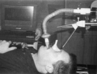
In this method, the patient’s nose is clamped and he or she breathes through an ABC apparatus via a mouthpiece, as shown in Fig. 11-9. The signal from the flow monitor is processed and a trace on the computer monitor displays the lung volume. During a particular sequence of the breathing cycle, at a predetermined flow direction and lung volume, a valve is activated to stop the airflow temporarily, resulting in the suspension of the breathing motion.21–23 The duration of the breath-hold is such that the patient can easily tolerate it. The amount of breath-hold a patient can tolerate depends on the disease site. For example, patients with lung disease can easily tolerate a breath-hold of 15 seconds near the end of normal inspiration, whereas for patients with Hodgkin’s disease and liver cancer, the breath hold ranges from 35 to 50 seconds when ABC is applied during inspiration.23 ABC can substantially reduce the treatment margins without the need to modify the therapy accelerator.
Deep Inspiration Breath Hold Technique
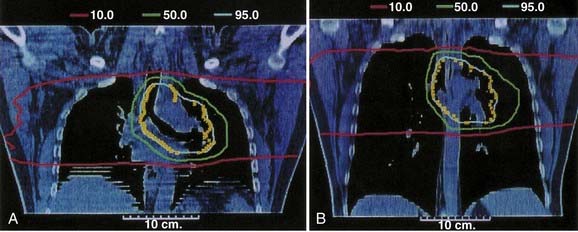
In this method the patient is coached on the technique of reproducible deep inspiration through the various phases of treatment planning and delivery.4,24,25 The DIBH uses a modified version of slow vital capacity maneuver26 to bring the patient to approximately 100% vital capacity, followed by a breath hold, which maintains the patient at that level for a prescribed period, during which the patient is simulated, CT-scanned, treated, and port filmed. The patient breaths through a mouthpiece connected to a spirometer control unit. A nose-clip is used to make sure that the patient breaths through the mouth. The spirometer measures the airflow and it is interfaced with a computer. The airflow is integrated to yield the lung volume as a function of time and is displayed on a computer monitor. The DIBH maneuver begins with quiet tidal breathing, followed by a slow deep inspiration, slow deep expiration, then a slow deep inspiration to the maximum limit and breath-hold. A training session is held to familiarize the patient with spirometer and to measure patient parameters, such as the tidal volume, vital capacity, and comfortable breath-hold duration. Some patients are unable to follow the directions and are unsuitable for DIBH. The technique has two advantages. First, the breath-hold minimizes tumor motion due to breathing. Second, it expands the patient lung to its maximum volume, pushing healthy lung tissue out of the primary radiation field and consequently reducing the fraction of the lung in the treatment beam. Fig. 11-10 compares the free breathing and DIBH treatment plans for a patient. The images are coronal planes through the isocenter for the same patient. Hanley et al.4 have found that DIBH can reduce the volume of the lung receiving more than 25 Gy by 30% compared to free-breathing plans. It is found to be highly reproducible. Patients could perform 10 to 13 breath holds in one session, with a comfortable breath-hold duration of 12 to 16 seconds.
Respiratory Gating
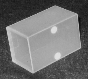
There are commercially available systems (for example, Real-time Position Management [RPM] Respiratory Gating; Varian Medical Systems, Palo Alto, CA) that permit breathing-synchronized fluoroscopy on a treatment simulator, acquisition of breathing-synchronized CT imaging, and gated treatment on a linear accelerator.5,27 The system consists of a charge-coupled-device (CCD) video camera attached to an infrared illuminator (Fig. 11-11) that tracks a patient’s respiratory motion by detecting reflected infrared light from two reflective markers on a lightweight block (Fig. 11-12). The block is placed on the patient’s chest or abdomen. The upper marker tracks the respiratory motion; the lower marker, separated by 3 cm from the upper marker, calibrates the system. The camera signal is processed by software. At the start of any session, whether simulation, CT, or treatment, the operator places the system into tracking mode for a few breathing cycles. This allows the system to determine the minimum and maximum vertical position of the upper marker. These values establish the scale of marker motion for subsequent display and for setting a gating threshold, as described later. At simulation, either amplitude or phase gating can be selected. For amplitude gating, the user adjusts the threshold levels that appear as two horizontal lines.
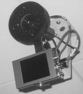
FIGURE 11-11 • Charge-coupled-device video camera attached to infrared illuminator for tracking the respiratory motion.
Simulation Process
Positioning of the Patient
Many issues are involved in defining the treatment position. The most important factor is comfort—the patient must be able to lie comfortably in the treatment position for the duration of the treatment. Alternatively, it may be necessary for the patient sit in a chair or in some other comfortable position during treatment. Depending on the site to be treated and the technique to be used, various institutions have preferred protocols for patient positioning. For example, to treat patients with prostate cancer, some institutions use a prone position,28 whereas others prefer a supine position.29 The next factor is that the position should be such that the treatment beams avoid unnecessary tissue irradiation. For example, for the treatment of patients with lung cancer, if lateral fields will be used, an arms-over-the-head position is preferable so that the treatment beams do not pass through the arms. For patients with brain tumors, if the treatment volume is located posteriorly, a prone position may be preferable. Relative positions of the internal organs, such as esophagus and bowel, change depending on how the patient is lying on the couch. One position may offer better normal-tissue sparing than the other. Fluoroscopic images can be helpful in making the decision.
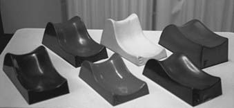
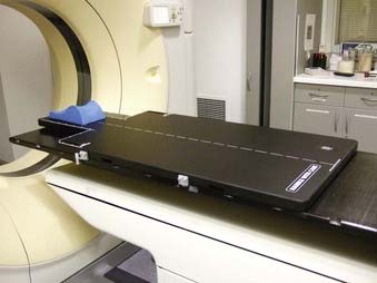
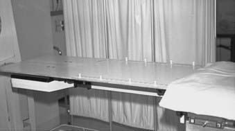
To help in positioning the patient, many commercial devices are available. These include head-and-neck supports, breast boards, pillows, and various types of straps. Head-and-neck supports (Fig. 11-13) are made of polyurethane foam or clear plastic, offering minimal attenuation for megavoltage x-rays. Various sizes provide different head angulations and neck extensions. The use of the same support during each treatment helps in day-to-day reproducible positioning of the patient. At times, to solve a specific problem it may be necessary to develop an individual positioning device. Fig. 11-14 shows a commercially available head-and-neck board to treat patients with conformal technique, which requires treatment with multiple posterior-lateral beams.2 The board is made of carbon fibers and the patient can be treated through the board with megavoltage x-rays. The patient’s head is supported at the smaller section of the board, which can extend beyond the edge of the couch. This position allows treatment with posterior-lateral beams without interference from the couch-support bars. Similarly, a prostate board, made of low-density wood (Fig. 11-15), helps in positioning and immobilizing the patient with prostate cancer. The board is placed on top of a tennis racket or on the open section of the couch. With the help of this board the patient can be treated without any sag. The clamps at the side hold the thermoplastic mold in place. For any nonroutine treatment situation, the radiation oncologist, the treatment planner, and the radiation therapist should discuss the positioning of the patient beforehand.
Immobilization of the Patient
Immobilization Devices
Thermoplastics
Thermoplastic sheets are available in different sizes and thicknesses, as perforated or solid sheets. Thermoplastic is rigid at room temperature, but when heated in a pan of water to temperatures in the range of 55° to 70° C, the material softens and becomes malleable.30 The softened sheet can be molded around the body part to be treated and the flared ends of the mask clamped to the supporting board. When thermoplastic cools down, it hardens and forms a rigid mask. Figure 11-16 shows a commercially available system (Postfix; Civco Medical Solutions, Kalona, IA) to immobilize patients for brain or head and neck treatment. Patients in a supine position on a headrest are immobilized with a thermoplastic mask that attaches to a carbon fiber base plate fixed to the treatment couch. The combination of a base plate and mask provides a system of accurate patient immobilization.
Gilbeau et al.31 have analyzed the setup accuracy of three different types of thermoplastic masks. The first type of mask (Fig. 11-16 A) fastens the head of the patient with three fixation points, two fixation points on both sides of the head and one on top of the head. The second type of mask (Fig. 11-16 B) has four fixation points, two on the sides of the head and two around the shoulder. As shown in Fig. 11-16 C, the third type has five fixation points. Gilbeau et al. found that for the isocenter located in the head and neck, there was no substantial difference in the setup deviation between the 3 masks. The setup reproducibility was found to be better at the shoulder level with a four- and five-point mask. A body cast to immobilize a prone prostate patient is shown in Fig. 11-17.
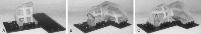
FIGURE 11-16 • Three types of masks for the head and neck: (A) three fixation points; (B) four fixation points; (C) five fixation points.
(From Gilbeau L, et al: Comparison of setup accuracy of three different thermoplastic masks for the treatment of brain and head and neck tumors, Rad Ther Oncol 58:155, 2001.)
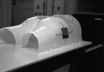
FIGURE 11-17 • Thermoplastic body cast to immobilize a prostate patient in prone treatment position.
Another method of making the masks is the vacuum-forming technique.32 First, a plaster cast is made as described previously. Then a positive plaster mold is constructed from the negative cast. Finally, the plastic cast is produced by vacuum forming over the positive mold. This results in a strong, clear lightweight mask that can be attached to a base plate.
Polyurethane Foam
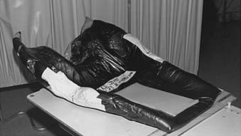
In this case, a cast is made by mixing two foaming agents (available under the trade name Alpha Cradle mold maker [Smithers Medical Products, Inc., North Canton, OH]), in a plastic bag. The patient is positioned on the top of this bag in the treatment position. As the two chemicals mix, foam is formed that fills up the bag. The bag conforms to the patient’s body shape. In about 15 minutes the foam hardens, providing a body cast. These casts are lightweight and provide rigid body support. For megavoltage x-rays, they produce little attenuation of the incident radiation. Fig. 11-18 shows a foam mold for immobilizing a patient with lung cancer.
Use of Contrast Material During Simulation
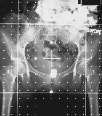
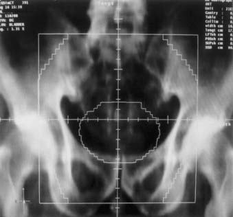
Radiopaque compounds with high atomic numbers, such as iodine and barium, and low-density materials, such as air are used to enhance radiographic contrast. The use of contrast material helps in identifying and isolating anatomic structures and diseased tissue in radiographs and CT scans. Contrast materials are available in various forms. Agents such as Renografin (Braco Diagnostics, Inc., Princeton, NJ) and Omnipaque (GE Healthcare, Princeton, NJ) can be administered intravenously. As the bloodstream carries the contrast material to different organs, the radiographic contrast of the organs change. Radiographic compounds such as Polibar (E-Z-EM Inc., Westbury, NY) and Gastrografin (Braco Diagnostics, Inc., Princeton, NJ) can be given orally to enhance the contrast of esophagus, stomach, and bowel. To increase the contrast of the rectum compared with the surrounding tissue, either a radiopaque compound or air is administered using a rectal catheter. A urinary Foley catheter with an inflatable balloon is used to visualize the bladder and urethra on the x-ray films. Fig. 11-19 shows an anterior-posterior simulation film of the pelvis. An oral contrast agent is used to enhance the visibility of the bowel, and a Gastrografin-soaked tampon is used for localizing the vagina on the radiograph.
Localization of the Disease
After the patient has been placed in the treatment position, aligned, and if necessary immobilized, a tentative isocenter and the treatment field sizes are selected based on the clinical information about the location and extent of the disease. Radiopaque catheters, wires, or small metal ball bearings (BBs) are taped to the patient’s skin to help in identifying any anatomic landmark, diseased tissue, or scar on the skin. Either a pair of orthogonal radiographs is taken or the patient is imaged fluoroscopically. These images are reviewed for coverage of the disease; if necessary the isocenter and the field sizes are adjusted. A complete set of radiographs that includes an orthogonal pair and x-ray films for each treatment field is obtained. In order to set up the isocenter reproducibly on a daily basis, the triangulation points for the isocenter and a few alignment points are tattooed on the patient’s skin. The alignment points are selected judiciously so that the patient can be brought back to treatment position without too much day-to-day variation. More emphasis is given to the bony anatomic landmarks than to the skin marks, particularly if the skin is flabby.33 The relevant beam parameters, such as gantry angles and field sizes, are recorded in the patient’s chart along with the set-up depth. Photographs of the patient’s set-up, obtained during the simulation, are helpful in day-to-day positioning of the patient for radiotherapy.
CT Simulation
Surface Markers
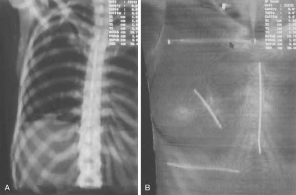
If some areas are of special interest (scars, previously treated area, skin nodules), they are highlighted with solder wire or BBs. However, if the CT artifacts because of metal wire and BBs are unacceptable, then nonmetallic high-density wires or small beads can be used instead. Wires and beads may not be so easily visible on the DRRs, but DCRs in which skin is highlighted show these skin markers clearly. Fig. 11-20A shows the DRR for a patient with breast cancer, and Fig. 11-20B is the DCR, in which the skin is highlighted and the makers are clearly visible.
Virtual Simulation
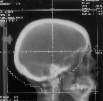
Depending on the complexity of the situation, the patient’s bony anatomy can be used to decide the beam orientation, field size, and block shape, as during a conventional simulation, but in place of radiographs DRRs are used. The image quality of the DRRs can be adjusted by changing the window and contrast. Fig. 11-21 shows the right lateral treatment port for a whole brain case.
Soft tissues are difficult to identify on the DRRs. In these cases the target and the normal tissues are contoured on the CT scans. The virtual software package contains the tools to help draw these contours. For example, if the CTV is drawn, then a predetermined margin can be added to define the PTV. Fig. 11-22 shows the anterior-posterior DRR for a pelvis field for a patient with bladder cancer.
Four-Dimensional Computed Tomography
Because of respiratory and cardiac activity, there is significant intrafraction motion for treatment sites such as lung, liver, pancreas, and, to a lesser extent, prostate and breast. The temporal anatomic changes due to respiratory motion are not accounted for during CT imaging for conventional radiotherapy techniques for thoracic and abdominal sites. Patient motion during CT imaging causes artifacts.34 Generally, for these sites a treatment planning CT scan is obtained under quiet breathing. If the scanning speed is much slower compared with the tumor motion speed a smeared tumor image is captured. However, if the CT scanning speed is much faster than the tumor motion speed, then the captured image is at an arbitrary breathing phase. If the scanning speed is comparable with the tumor motion speed, which is the case for the modern helical CT scanners.35 The captured tumor position and shape can be heavily distorted. As discussed earlier, some of these problems can be reduced with the interventional techniques, such as active breathing control, DIBH, and RPM gating, so that the images are acquired at a particular breathing phase.
A method to address the respiratory motion problem is to use four-dimensional (4D) or tumor-tracking imaging. It can be defined as acquisition of a sequence of CT image sets over consecutive segments of a breathing cycle.34 Generally, a respiratory sensor is used to obtain a signal that is surrogate for the tumor motion due to breathing movement. Two devices are commonly used for sensing breathing motion. One is the air bellow system, as shown in Fig. 11-23. It is an elastic belt positioned around the abdomen that expands and contracts with respiratory motion. It contains a pressure transducer which converts pressure changes to an electrical signal.36 This electrical signal representing respiratory motion is displayed at the CT console and it is interfaced with the CT scanner. CT images are obtained in synchrony with the respiratory signal. The other system is RPM respiratory gating, an optical method described earlier. Four-dimensional CT images can be obtained in axial mode on a single-slice or multislice scanner. Or, as described by Keall et al.,37 these images can be obtained in helical mode on a multislice scanner.
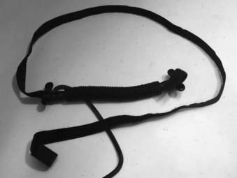
FIGURE 11-23 • Respiratory air bellow belt for sensing the breathing motion and generating the electrical signal for 4DCT.
After the 4D scan is complete, the CT images are sorted corresponding to breathing phase. Generally, the complete breathing cycle is divided into 10 evenly distributed phases. Thus, ten complete three-dimensional image sets are obtained—each corresponding to a partial breathing phase. Together, the set constitutes the 4DCT set. However, this technique has unique challenges such as imaging dose, CT tube heating, and data management. Furthermore, 4DCT scan is not really 4D, since temporal information is mapped into one breathing cycle. Irregular breathing, particularly variations in amplitude between breathing cycles, will cause artifacts in 4DCT images. A solution is to coach the patient in regular breathing.35
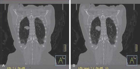
How to use this voluminous data for patient treatment planning and treatment? This is an active area of investigation. One approach is to outline the GTV and CTV on all phases, project this information on the planning CT, and determine the internal target volume ITV.38 Lung is one of the sites where breathing motion is of primary concern—to address this, the use of maximum intensity projection (MIP) has been suggested39 to determine the extent of ITV. MIP represents the greatest density voxel obtained when considering images for all phases. Fig. 11-24A shows the reconstructed coronal plane through the tumor for a lung patient, based on treatment planning CT scan. The tumor is located in the right lung. Fig. 11-24B shows the MIP image, for the same patient, based on 4DCT. However, one needs to be careful, when using MIP image to generate ITV if significant respiratory variability is present.40
Methods for Obtaining External Patient Contours
If a treatment plan is needed for radiation therapy, the external contours are obtained. Usually, the contour is taken through the central axis of the beam. If the patient’s thickness changes significantly within the treatment field, contours in more than one plane are taken. The best method for obtaining patients’ external contours is the treatment planning CT. A CT scan provides the external contour and the location of the disease and internal organs. If a treatment planning CT is not available, various methods and devices can be used for obtaining the contours. Some devices are available commercially, whereas others have been described by researchers and can be constructed locally. The devices use mechanical,41 optical,42 ultrasonographic,43 and electromechanical methods.44
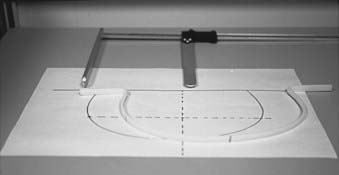
A long thermoplastic contour tube or strip can also be used instead of a solder wire. The low-temperature thermoplastic is heated in a pan of water and shaped in the patient’s contour; as the thermoplastic cools it hardens and the contour shape is retained. The plaster of Paris bandage provides an alternative method of obtaining the external contour. Sufficient length of the bandage to obtain the contour and reach the tabletop on both the sides is taken. It is folded along the width to a strip approximately 1 cm wide and thick enough to provide rigidity. The bandage is wetted and molded along the patient’s skin. Sufficient time is allowed for the strip to harden; the relevant points are marked; and the strip is carefully removed. With a pencil, the shape outline is transferred to a sheet of paper. Fig. 11-25 shows a contour obtained with the help of a thermoplastic strip.
Treatment Decision
Treatment Planning from Contours
If the target volume is close to critical organs and the intent is to limit the dose to these organs during radiation therapy, it may be necessary to design a treatment plan. The contours necessary for the plan are obtained either during the simulation or by a treatment planning CT scan. The information about the location of the disease and critical structures is provided by the physician on the simulation radiographs or on the treatment planning CT images or both. A digitizer can be used to enter the information about the contours into the treatment planning system. Generally, the external contours obtained using one of the mechanical methods are life-size and can be digitized directly. The small hard copies of the CT images can be enlarged to true size using an enlarger. The outer contour, internal organs, and target volume can be projected and traced onto a paper and then digitized into the treatment planning computer. A magnification grid on a CT image is valuable for treatment planning. It can be used for alignment and verifying the magnification along the horizontal and vertical directions. If a treatment planning system has the option of digitizing at a lower magnification, contours can be digitized directly from the CT hard copies using a light box (Fig. 11-26). Sometimes, a magnifying lens with cross hair helps in entering the data accurately. Most treatment planning systems allow planning with the CT images; the external contour and the internal structures can be outlined directly on a video monitor by means of a light pen or some other pointing device.
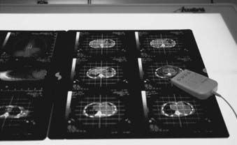
Image Registration
Computed Tomography–Based Three-Dimensional Planning
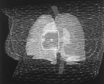
Three-dimensional treatment planning systems use a set of CT scans for the treatment planning,45–49 versus a contour as for the traditional plan. These systems offer more flexibility in planning, and the dose calculations are more accurate. Investigators have compared the 3D plans with the traditional two-dimensional (2D) plans and have found that the 3D plans can offer better target coverage and reduced dose to normal tissues.50 For 3D treatment planning, the CT data are transferred to the planning system and the relevant structures, including the skin, bony landmarks, and critical structures, are outlined. Once the structures have been entered, they can be viewed from the BEV perspective. The BEV for a patient with lung cancer is shown in Fig. 11-27. Some of the normal structures, including the skin and the target volume, are shown as wire frames. The aperture outline (in white) has been drawn to cover the target but to exclude the spinal cord. As the gantry and the couch angles are varied, the view changes interactively. The planner can select the beams that treat the target while minimizing the dose to the surrounding tissues. Because the CT number is proportional to the electron density, the dose calculations for the plans can use the CT numbers to correct for the tissue in homogeneities. Planning with noncoplanar beams is easier on a 3D treatment planning system. For a 3D plan, if the isocenter is moved or if there are treatment beams for which no radiographs were initially taken, a plan check or resimulation is carried out to obtain a complete set of radiographs. However, if the DRRs are used instead of the radiographs, there is generally no need to bring the patient back.
Plan Check or Resimulation
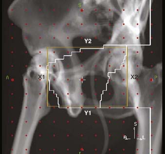
Volumetric CT data are used for 3D treatment planning. Based on these data, DRRs can be constructed. Fig. 11-28 shows the DRR for a left-anterior-oblique treatment field for a patient with prostate cancer on which the treatment aperture, cross hair, graticule markers, and collimators are projected.
In some cases, a DRR can be constructed, but it is not feasible to obtain a simulation radiograph (e.g., it is impossible to radiograph a vertex field). In such cases, one of the orthogonal films can be used for verification of the aperture shape. An anterior simulation radiograph can be used to draw the block shape for a vertex field. The orthogonal pair of films verifies the treatment isocenter, and the aperture shape is verified on the anterior localization port film. This film is just for verification; the beam pointing in the vertex direction delivers the actual treatment. Reisinger and colleagues51 describe a verification technique for the vertex field. In this technique, the exposures from a lateral field and the vertex fields are superimposed on a localization port film. First, a double-exposure localization port film for one of the lateral fields is obtained. Then, without moving the film or the patient, one sets up the vertex field by rotating the treatment couch 90°. The table is moved laterally so that the film in the cassette holder is in the radiation axis plane. The couch is shifted inferiorly to obtain the same magnification as for the lateral field. The final film exposure is made so that the vertex field is superimposed on the film. The isocenter position and field size for the vertex fields are verified by this method.
Transfer of Treatment Information to the Therapy Machine
In computer-controlled therapy machines, treatment parameters for the beams can be downloaded directly from the treatment planning computer to the treatment machine’s computer.52 These machines are capable of automatically setting each beam and delivering the whole treatment without operator intervention. It has been suggested that a virtual treatment or “dry run” be carried out before actual treatment delivery to ensure patient safety during the automatic gantry and couch motion. During the virtual treatment the patient is placed in the therapy position and the operator takes the machine through the whole treatment sequence—but without radiation—while keeping the motion enable switch depressed. This ensures that a collision situation does not exist during the machine and couch movement.
Treatment Verification
On the basis of instructions generated during the simulation and treatment planning, the patient is placed in the treatment position. To verify the correctness of the setup, the patient is imaged directly on the treatment machine with the shielding blocks or MLCs in place. This process is carried out before treatment and serves two purposes. First, it confirms that the patient is set up correctly and the shielding blocks are protecting the normal structures as planned. Second, it documents the patient’s position for future reference. It has also been shown that frequent treatment verification reduces localization errors.53
Portal Imaging With Films
Portal Localization
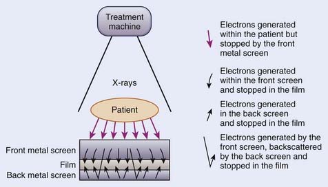
A portal localization radiograph is obtained by exposing a radiographic film in a specially designed cassette with a metal screen. Only a fraction of the treatment beam-on time is used for the exposure. Droege and Bjarngard54 investigated the screen-film combinations for portal imaging. Fig. 11-29 shows a screen-film combination. The purpose of the front metal screen is to prevent the electrons generated within the patient from reaching the film and to generate electrons for the radiographic image production. The purpose of the high–atomic number back screen, if used, is to serve as an intensifier and to provide additional film exposure. The use of a back screen results in higher speed at the cost of slight reduction in resolution. To expose a portal localization film a double-exposure technique is used. The first exposure is given with the treatment field size and shielding blocks in place. For the second exposure, a graticule tray replaces the blocks and an open field is used. The resulting image contains the image of the shaping block, the surrounding anatomic structures, and grid points that serve as the cross hairs, and scale for measurement. These films are compared with the simulation films to verify the treatment port shape and its location with respect to the patient’s anatomy.
Portal Verification
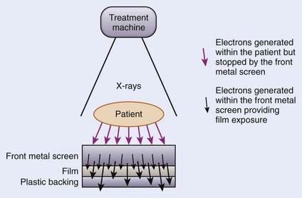
For portal verification, a slow film with or without a screen is used. To obtain the radiograph, one exposes the film to the exit radiation for the duration of the treatment. Figure 11-30 schematically shows the film-screen combination for portal verification. In this case, the function of the front metal screen is the same, to stop the electrons generated within the patient from reaching the film and to produce electrons for the radiographic image. A second metallic back screen is not used; instead, a plastic backing is used to provide support for the film and to eliminate artifacts from backscattered radiation. These radiographs image only the treatment area; the surrounding anatomic structures are not imaged.
Electronic Portal Imaging
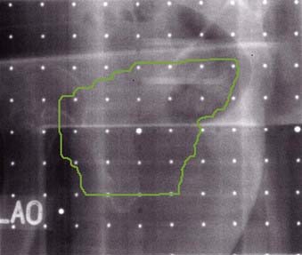
For electronic portal imaging, instead of a film, an electronic portal imaging device (EPID) is placed in the exit beam to produce the image. The images are captured and displayed on a video screen. Boyer et al.55 and Antonuk56 have reviewed the existing EPIDs. EPIDs produce images almost instantaneously and store the images digitally on a computer. The images can be processed on the computer to enhance various attributes.57 These images can be compared with the simulation films to determine the placement differences.58 The patient can be monitored throughout the treatment, and motion during the therapy can be detected. One of the video-based systems is shown schematically in Fig. 11-31.59 As the x-ray beam passes through the patient, its intensity is modulated by the inhomogeneity of the patient’s anatomic structures. The exiting photon beam strikes the metal plate coated with phosphorous material to produce fluorescence. A video camera and computer combination digitally record the resulting light and display the images on a video monitor. A mirror inclined at a 45° angle allows the video camera to be out of the direct radiation beam. The whole system is packaged in a collapsible housing. When the device is not in use, it can be retracted.
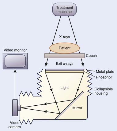
FIGURE 11-31 • Schematic diagram of the components of a video-based electronic portal imaging device.
Another type of EPID uses a matrix of liquid ion chambers as detectors (Fig. 11-32).60,61 This system consists of a 256 × 256 matrix of ionization chambers. An organic liquid serves as the ionizing medium between the electrodes. The ionization current in each chamber is measured with a current-to-voltage converting electrometer. An analog-to-digital converter, providing the intensity information for the pixel corresponding to the ionization chamber, then digitizes the collected charge. The matrix ion chambers, metal screens, and support electronics are packaged in a compact cassette form, which can be mounted on the gantry.
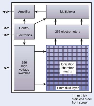
FIGURE 11-32 • Schematic diagram of a matrix-ionization chamber electronic portal imaging device.
(Redrawn from Boyer AL, Antonuk L, Fenster A, et al: A review of electronic portal imaging devices [EPIDs], Med Phys 19:1, 1992.)
Currently, active matrix flat panel imagers (AMFPIs) are available for portal imaging.56,62 AMFPI technology consists of ~1-mm-thick glass substrate on which thin-film electronic circuits reside. These circuits are created through a series of semiconductor processing steps. This solid state technology creates compact detectors that can be easily mounted on therapy accelerator. One of the advantages of the AMFPI based portal images is the high degree of image quality. Furthermore, these detectors are highly radioresistant. However, readout circuits located at the periphery of the array are radiosensitive. During the use these circuits should be protected from direct radiation. Figure 11-33 shows a portal image for an oblique beam for a prostate patient, obtained with an amorphous silicon detector.
Computed Radiography Systems
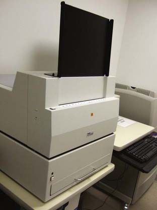
Computed radiography (CR) systems are very similar to film-based systems, but instead of film, a photostimulable phosphor plate is used. These flexible plates are 1 mm thick and are coated with europium activated fluorohalide compounds in crystalline formation embedded in organic binding material.63 When the plate is exposed to ionizing radiation, photostimulable phosphor stores the latent image. When the plate is scanned with a red laser beam, stored energy is released as visible light. The emitted light is detected by a photomultiplier tube and converted to electric signals. These electrical signals are processed and converted to a digital image. The stored information on the plates can be erased by exposing it to room-level fluorescent light, and then these plates can be reused. Compared to films, CR images are of good quality. Some advantages of the CR system are: (1) the same plate can be used again and again; (2) it does not require a dark room and developing chemicals; (3) the produced image is digital and can be stored and manipulated electronically; (4) these images have greater dynamic range, wider exposure latitude and reduced patient exposure.64 These systems are commercially available from vendors such as Kodak, Fuji, and Agfa. Fig. 11-34 shows a Kodak CR system.
On-Board Imager and Cone-Beam
In order to verify the placement of the treatment fields, MV portal imaging generally is used. However, the image quality is poor because of the low subject contrast of bony anatomy at megavoltage energies.55 To overcome this limitation, addition of a kV source and imager to a linac was demonstrated by Jaffray et al.65 This generates high-resolution soft tissue images of the patient at the time of treatment for the purpose of guiding therapy and reducing uncertainties. Currently, the machines with an additional on-board kV imaging system along with MV imager are available commercially. The combined system consists of medical accelerator and two imaging systems (MV and kV). This is also referred as the dual-beam system. Fig. 11-35 shows a commercially available linac with kV and MV imaging systems. In addition to the improved image quality of the kV imaging, the dose delivered during kV exposure is significantly lower compared to dose for MV imaging. The reduction is dose allows for more frequent imaging and acquisition of images at nontreatment gantry angles, which may improve the precision of localization.65
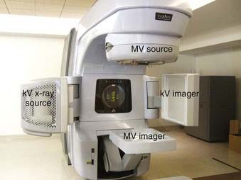
FIGURE 11-35 • A modern therapy accelerator with kV and MV imaging systems. Motorized mounts allow detector movement.
During CBCT, the gantry rotates around the patient while acquiring hundreds (~700) of low-dose radiographs. From these projections, axial CT images are reconstructed. When the detector is centered about the rotational axis and the source to imager distance (SID) is 150 cm, the reconstructed field of view is ~24 cm. This mode of acquisition is called full-fan and is used for small-diameter anatomic sites such as brain and head and neck. For larger anatomic sites, the detector is shifted by 14.8 cm laterally and blades in the x-ray source track the detector during gantry rotation. The image reconstruction is done by piecing together images acquired 180° apart. This acquisition mode is called half-fan. The field of view in half-fan mode is ~45 cm. An accessory, called a bowtie filter, is placed in front of the kV beam to attenuate the edges of the kV beam. This filter reduces the skin dose, allows larger x-ray technique without saturating the detector, and reduces x-ray scatter and the effect of charge trapping in the detector.66
Image-guided radiotherapy using the on-board imager relies on different components to work together. A regular quality assurance program as described by Yoo et al.66 to detect changes in the imaging chain is needed to make sure that the patient is imaged and treated properly.
1 Hall EJ. Radiobiology for the radiologist, ed 4. Philadelphia: JB Lippincott; 1994. p 211
2 Leibel SA, Kutcher GJ, Harrison LB, et al. Improved dose distribution for three-dimensional conformal boost treatments in carcinoma of the nasopharynx. Int J Radiat Oncol Biol Phys. 1991;20:823.
3 de Arruda FF, Puri DR, Zhung J, et al. Intensity-modulated radiation therapy for the treatment of oropharyngeal carcinoma: the Memorial Sloan-Kettering Cancer Center experience. Int J Radiat Oncol Biol Phys. 2006;64:363.
4 Hanley J, Debois MM, Mah D, et al. Deep inspiration breath-hold technique for lung tumors: the potential value of target immobilization and reduced lung density in dose escalation. Int J Radiat Oncol Biol Phys. 1999;45:603.
5 Mageras GS, Yorke E, Rosenzweig K, et al. Fluoroscopic evaluation of diaphragmatic motion reduction with respiratory gated radiotherapy system. J Appl Clin Med Phys. 2001;2:191-200.
6 Hounsfield GN. Computed medical imaging. Med Phys. 1980;7:283.
7 Crawford CR, King KF. Computed tomography scanning with simultaneous patient translation. Med Phys. 1990;17:967.
8 Arkadiusz P, Kalender W, Brink J, et al. Measurement of slice sensitivity profiles in spiral CT. Med Phys. 1994;21:133.
9 Vock P, Soucek M, Daepp M, et al. Lung: spiral volumetric CT with single-breath-hold technique. Radiology. 1990;176:864.
10 Goitein M. Computed tomography in planning radiation therapy. Int J Radiat Oncol Biol Phys. 1979;5:445.
11 Lichter AS, Fraass BA, van de Geijn J, et al. An overview of clinical requirements and clinical utility of computed tomography based radiotherapy treatment planning. In: Ling CC, Rogers CC, Morton RJ, editors. Computed tomography in radiation therapy. New York: Raven Press; 1983:1.
12 Sherouse GW, Mosher CE, Novins K, et al. Virtual simulation: concept and implementation. In: Bruinvis IAD, van der Giessen PH, van Kleffens HJ, Wittkamper FW, editors. the use of computers in radiation therapy. Amsterdam: Elsevier Science; 1987:433.
13 Sherouse GW, Bourland JD, Reynolds K, et al. Virtual simulation in the clinical setting: some practical considerations. Int J Radiat Oncol Biol Phys. 1990;19:1059.
14 Sherouse GW, Chaney EL. The portable virtual simulator. Int J Radiat Oncol Biol Phys. 1991;21:475.
15 Sherouse GW, Novins K, Chaney EL. Computation of digitally reconstructed radiographs for use in radiotherapy treatment design. Int J Radiat Oncol Biol Phys. 1990;18:651.
16 Goitein M. CT Simulation: an overview. In: Jani SK, editor. CT simulation for radiotherapy. Madison: Medical Physics; 1993:161.
17 Wen BC, Pennington E, Jani S. Clinical applications of CT simulators in unconventional radiation therapy techniques. In: Jani SK, editor. CT simulation for radiotherapy. Madison: Medical Physics; 1993:129.
18 Butker EK, Helton DJ, Keller JW, et al. Practical implementation of CT-simulation: the Emory experience. In: Purdy J, Starkschall G, editors. A practical guide to 3-d planning and conformal radiation therapy. Middleton, WI: Advanced Medical Publishing, Inc.; 1999:57.
19 Garcia-Ramirez JL, Mutic S, Dempsey JF, et al. Performance evaluation of an 85-cm-bore x-ray computed tomography scanner designed for radiation oncology and comparison with current diagnostic CT scanner. Int J Radiat Oncol Biol Phys. 2002;52:1123.
20 Chen GTY, Pelizzari CA, Hamilton RJ, et al. Image Processing and Integration in Oncologic Imaging. In: Bragg DG, Rubin P, Hricak H, editors. Oncologic imaging. ed 2. Philadelphia: W.B. Saunders Company; 2002:92.
21 Yan D, Wong J, Vicini F, et al. Adaptive modification of treatment planning to minimize the deleterious effect of treatment setup error. Int J Radiat Oncol Biol Phys. 1997;38:197.
22 Wong JW, Sharpe MB, Jaffray DA, et al. The use of active breathing control (ABC) to reduce margin for breathing motion. Int J Radiat Oncol Biol Phys. 1999;44:911.
23 Wong JW, Yan D, Jaffray DA, et al. Interventional strategies to optimize the delivery of radiation therapy. In: Bragg DG, Rubin P, Hricak H, editors. Oncologic imaging. ed 2. Philadelphia: W.B. Saunders Company; 2002:116.
24 Rosenzweig KE, Hanley J, Mah D, et al. The deep inspiration breath hold technique in treatment of inoperable non-small cell lung cancer. Int J Radiat Oncol Biol Phys. 2000;48:81.
25 Mah D, Hanley J, Rosenzweig KE, et al. Technical aspects of deep inspiration bearth-hold technique in the treatment of thoracic cancer. Int J Radiat Oncol Biol Phys. 2000;48:1175.
26 American Thoracic Society. Standardization of spirometry. Am J Respir Crit Care Med. 1994;152:1107.
27 Ford EC, Mageras GS, Yorke E, et al. Evaluation of respiratory movement during gated radiotherapy using film and electronic portal imaging. Int J Radiat Oncol Biol Phys. 2002;52:522.
28 Leibel SA, Heimann R, Kutcher GJ, et al. Three-dimensional conformal radiation therapy in locally advanced carcinoma of the prostate: Preliminary results of a phase I dose-escalation study. Int J Radiat Oncol Biol Phys. 1994;28:55.
29 Ten Haken RK, Perez-Tamayo C, Tesser RJ, et al. Boost treatment of the prostate using shaped, fixed fields. Int J Radiat Oncol Biol Phys. 1989;16:193.
30 Gerber RL, Marks JE, Purdy JA. The use of thermal plastics for immobilization of patients during radiotherapy. Int J Radiat Oncol Biol Phys. 1982;8:1461.
31 Gilbeau L, Octave-Prignot M, Loncol T, et al. Comparison of setup accuracy of three different thermoplastic masks for the treatment of brain and head and neck tumors. Radiat Ther Oncol. 2001;58:155.
32 Devereux C, Grundy G, Littman P. Plastic molds for patient immobilization. Int J Radiat Biol Phys. 1976;1:553.
33 Khan FM. The physics of radiation therapy, ed 2. Baltimore: Williams & Wilkins; 1994. p 307
34 Keall P. 4-dimensioanl computed tomography imaging and treatment planning. Semin Radiat Oncol. 2004;14:81.
35 Jiang SB. Radiotherapy of mobile tumors. Semin Radiat Oncol. 2006;16:239.
36 Kahler PJ, Subramanian P, Yanof JH. Respiratory correlated multislice CT for radiation therapy planning: imaging and visualization methods. Medicamundi. 2005;49:34.
37 Keall PJ, Starkschall G, Shukla H, et al. Acquiring 4D thoracic CT scans using multislice helical method. Phys Med Biol. 2004;49:2053.
38 International Commission on Radiation Units and Measurements, Prescribing, recording, and reporting photon beam therapy, Supplement to report 50. Report 62; 1999; ICRU, Washington, DC.
39 Underberg RWM, Lagerwaard FJ, Slotman BJ, et al. Use of maximum intensity projections (MIP) for target volume generation in 4DCT scan for lung cancer. Int J Radiat Biol Phys. 2005;63:253.
40 Jing C, Read PW, Baisden JM, et al. Estimation of error in intensity projection-based internal target volume of lung tumors: A simulation and comparison study using dynamic magnetic resonance imaging. Int J Radiat Oncol Biol Phys. 2007;69:895.
41 Stern BE, Hodges GB. A pentograph for body contours. Br J Radiol. 1957;30:613.
42 Clayton CB, Thompson DJ. An optical apparatus for reproducing outlines of body cross-section. Br J Radiol. 1970;43:489.
43 Day MJ, Harrison RM. Cross-sectional information and treatment simulation. In: Bleehen NM, Glatstein E, Haybittle JL, editors. Radiation therapy planning. New York: Marcel Dekker; 1983:87.
44 Doolittle AM, Berman LB, Vogel G, et al. An electronic patient contouring device. Br J Radiol. 1977;50:135.
45 Fraass BA, McShan DL. 3-D Treatment Planning: I. Overview of a clinical planning system. In: Bruinvis IAD, van der Giessen PH, van Kleffens HJ, Wittkamper FW, editors. The use of computers in radiation therapy. Amsterdam: Elsevier Science; 1987:273.
46 Purdy JA, Wong JW, Harms WB, et al. Three dimensional treatment planning system. In: Bruinvis IAD, van der Giessen PH, van Kleffens HJ, Wittkamper FW, editors. The use of computers in radiation therapy. Amsterdam: Elsevier Science; 1987:277.
47 Mohan R, Barest G, Brewster L, et al. A comprehensive three-dimensional radiation treatment planning system. Int J Radiat Oncol Biol Phys. 1988;15:481.
48 Sailer SL, Chaney EL, Rosenman JG, et al. Treatment planning at the University of North Carolina at Chapel Hill. Semin Radiat Oncol. 1992;2:267.
49 Photon Treatment Planning Collaborative Working Group. State-of-the-art of external photon beam radiation treatment planning. Int J Radiat Oncol Biol Phys. 1991;21:9.
50 Armstrong JG, Burman C, Leibel S, et al. Conformal three-dimensional treatment planning may improve the therapeutic ratio of high dose radiation therapy for lung cancer. Int J Radiat Oncol Biol Phys. 1993;26:685.
51 Reisinger SA, Palta J, Tupchong L. Vertex field verification in the treatment of central nervous system neoplasms. Int J Radiat Oncol Biol Phys. 1992;23:429.
52 Mageras GS, Podmaniczky KC, Mohan R. A model for computer-controlled delivery of 3-D conformal treatments. Med Phys. 1992;19:945.
53 Marks JE, Haus AG, Sutton HG, et al. The value of frequent treatment verification films in reducing localization error in the irradiation of complex fields. Cancer. 1976;37:2755.
54 Droege RT, Bjarngard BE. Influence of metal screens on contrast in megavoltage x-ray imaging. Med Phys. 1979;6:487.
55 Boyer AL, Antonuk L, Fenster A, et al. A review of electronic portal imaging devices (EPIDs). Med Phys. 1992;19:1.
56 Antonuk LE. Electronic portal imaging devices: a review and historical perspective of contemporary technologies and research. Phys Med Biol. 2002;47:R31.
57 Leszczynski KW, Shalev S, Ryder S. A study of efficacy of digital enhancement of on-line portal images. Med Phys. 1992;19:999.
58 Bijhold J, Gilhuijs GA, van Herk M. Automatic verification of radiation field shape using digital portal images. Med Phys. 1992;19:1007.
59 Munro P, Rawlinson JA, Fenster A. A digital fluoroscopic imaging device for radiotherapy localization. Int J Radiat Oncol Biol Phys. 1990;18:641.
60 Van Herk M, Meertens H. A digital imaging system for portal verification. In: Bruinvis IAD, van der Giessen PH, van Kleffens HJ, Wittkamper FW, editors. The use of computers in radiation therapy. Amsterdam: Elsevier Science; 1987:371.
61 Meertens H, van Herk M, Bijhold J, et al. First clinical experience with a newly developed electronic portal imaging device. Int J Radiat Oncol Biol Phys. 1990;18:1173.
62 Antonuk LE, El-Mohri Y, Jee KW. Active matrix flat-panel imagers (AMFPIs) for electronic portal imaging. In: Hazel JD, Boyer AL, editors. Imaging in radiation therapy; American Association of Physicists in Medicine 1998 Summer School Proceedings. Madison, Wisconsin: University of Wisconsin; 1998:371.
63 Kirby MC, Glendinning AG. Developments in electronic portal imaging systems. Br J Radiol. 2006;79:S50.
64 Bradford CD, Peppler WW. Performance characteristics of a Kodak computed radiography system. Med Phys. 1999;26:27.
65 Jaffray DA, Drake DG, Moreau M, et al. A radiographic and tomographic imaging system integrated into a medical linear accelerator for localization of bone and soft-tissue targets. Int J Radiat Oncol Biol Phys. 1999;45:773.
66 Yoo S, Kim GY, Hammoud R, et al. A quality assurance program for the on-board imager. Med Phys. 2006;33:4431.