Chapter 35 Imaging the chest
RADIOLOGICAL TECHNIQUES
Of the imaging techniques available for investigating patients in the intensive care unit (ICU), the chest radiograph remains the most important, with ultrasound being utilised in a selected group of patients. High-resolution and spiral computed tomography (CT) allow further investigation of these patients in certain situations.
DIGITAL CHEST RADIOLOGY
In the ICU, digital chest radiographs may be obtained utilising conventional X-ray generators, but the image is captured on a reusable photostimulable plate instead of conventional film. The digital information is then manipulated, displayed and stored in whatever format is desired. Traditional systems suffer greatly from the large day-to-day variations in the density of the radiograph due to small differences in exposure. Digital radiographic systems are able to capture and display a standard density image from a much wider range of exposures (Figure 35.1).
COMPUTED TOMOGRAPHY
HIGH-RESOLUTION COMPUTED TOMOGRAPHY (HRCT)
Narrow collimation images of the lung correlate closely with the macroscopic appearances of pathological specimens. In diffuse lung disease, HRCT allows a substantial improvement in diagnostic accuracy compared with chest radiography. Narrow section images can be acquired either as part of a volumetric acquisition or as interspaced images, usually 1.5 mm thickness, obtained every 1 cm. The radiation burden to the patient of this interspace or sequential technique is considerably less than with volumetric scanning – typically by a factor of 10 times.
CLINICAL APPLICATIONS OF HRCT IN THE ICU PATIENT
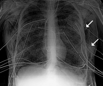
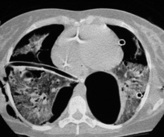
HRCT in uncomplicated acute respiratory distress syndrome (ARDS):1
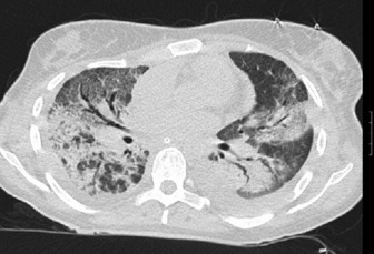
HRCT of complications of ARDS2,3
NORMAL RADIOGRAPHIC ANATOMY
THE MEDIASTINUM, CENTRAL AIRWAYS AND HILAR STRUCTURES
Appreciation of abnormality requires a sound grasp of normal radiological anatomy. The mediastinum is delimited by the lungs on either side, the thoracic inlet above, the diaphragm below and the vertebral column posteriorly. Because the various structures that make up the mediastinum are superimposed on each other on the chest radiograph, they cannot be separately identified. Nevertheless, because a chest radiograph is usually the first imaging investigation, it is necessary to have an appreciation of the normal appearances of the mediastinum, together with variations due to the patient’s body habitus and age. Key points include:
THE PULMONARY FISSURES, VESSELS AND BRONCHI
The two lungs are separated by the four layers of pleura behind and in front of the mediastinum. The resulting posterior and anterior junction lines are often visible on chest radiographs as nearly vertical stripes, the posterior junction line lying higher than the anterior. The junction lines are not invariably seen and their presence or absence is not usually of significance (Figure 35.3).
The upper and lower lobes of the left lung are separated by the major (or oblique) fissure. The upper, middle and lower lobes of the right lung are separated by the major fissure and the minor (horizontal or transverse) fissure. The minor fissure is visible in over half of normal PA chest radiographs. The major fissures are not visible on a frontal radiograph and are inconstantly identifiable on lateral radiographs. In a few individuals, fissures are incompletely developed; a point familiar to thoracic surgeons performing a lobectomy, because of incomplete cleavage between lobes. Accessory fissures are occasionally seen.
THE DIAPHRAGM AND THORACIC CAGE
The interface between aerated lung and the hemidiaphragms is sharp and the highest point of each dome is normally medial to the mid-clavicular line. The right dome of the diaphragm is higher than the left by up to 2 cm in the erect position unless the left dome is elevated by air in the stomach (Figure 35.4).
POSITIONING OF TUBES AND LINES4
CENTRAL VENOUS CATHETERS (CVC)
The end of a CVC needs to be intrathoracic, and is ideally in the superior vena cava. CVCs may be introduced via an antecubital, subclavian or jugular vein. Subclavian venous puncture carries a risk of pneumothorax and mediastinal hematoma. Rarely, perforation of the subclavian vein leads to fluid collecting in the mediastinum or pleura. All catheters have a potential risk of coiling, misplacement, knotting and fracture (Figure 35.5). The tip should not abut the vessel wall at an obtuse angle.
PULMONARY ARTERY FLOTATION CATHETERS
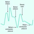
Ideally the end of the catheter should be maintained 5–8 cm (2–3 inches) beyond the bifurcation of the main pulmonary artery in either the right or left pulmonary artery (see Figure 35.5). When the pulmonary artery occlusion pressure is measured the balloon is inflated, and the flow of blood carries the catheter tip peripherally, to an occluded position. After the measurement has been made the balloon is deflated and the catheter returns to a central position; otherwise there is a risk of pulmonary infarction. The inflation balloon is radiolucent. The balloon should normally be kept deflated.
NASOGASTRIC TUBES
These should reach the stomach but may coil in the oesophagus or occasionally are inserted into the tracheobronchial tree (Figure 35.6).
ENDOTRACHEAL TUBES
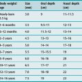
Extension and flexion of the neck may make the tip of an endotracheal tube move by as much as 5 cm. With the neck in neutral position the tip of the tube should ideally be about 5–6 cm above the carina. A tube that is inserted too far usually passes into the right bronchus, with the risk of non-ventilation or collapse of the left lung (Figure 35.7).
PLEURAL TUBES
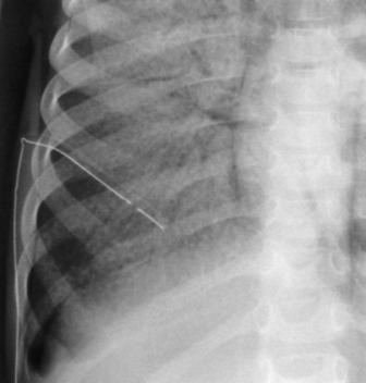
These are used to treat pleural effusions and pneumothoraces. A radiopaque line usually runs along pleural tubes, and is interrupted where there are side holes. It is important to check that all the side holes are within the thorax. Tracks may remain on the chest X-ray following removal of chest tubes, causing tubular or ring shadows. When doubt remains about tube position, then CT scanning should be considered (Figure 35.1 and 35.8).
INTRA-AORTIC BALLOON PUMP
These are used in patients with cardiogenic shock, often following cardiac surgery. The ideal position of the catheter tip is just distal to the origin of the left subclavian artery (Figure 35.9). If the catheter tip is advanced too far it may occlude the left subclavian artery, and if it is too distal the balloon may occlude branches of the abdominal aorta. The intra-aortic balloon pump may only be visible by its radiopaque tip (see Figure 35.5).
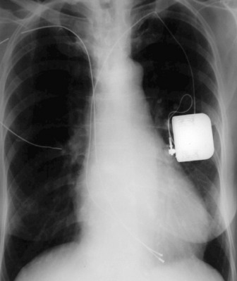
PACEMAKERS
These may be permanent or temporary (Figure 35.10). Temporary epicardial wires are sometimes inserted during cardiac surgery, and may be seen as thin, almost hair-like metallic opacities overlying the heart. Temporary pacing electrodes are usually inserted transvenously via a subclavian or jugular vein. If a patient is not pacing properly, a chest X-ray may reveal that the position of the electrode tip is unstable, or a fracture in the wire may be seen.
RADIOGRAPHIC SIGNS OF PATHOLOGY
CONSOLIDATION
Consolidation, or synonymously air space shadowing, is due to opacification of the air-containing spaces of the lung, usually without a change in volume of the affected area. It is not possible to tell what the air space filling is due to in the absence of a clinical history, except perhaps for shadowing due to cardiogenic alveolar oedema, when there will be associated signs of cardiac failure. Typical features of all forms of consolidation (Figure 35.11) include:
COLLAPSE
The direct signs of collapse include:
The indirect signs of collapse include:
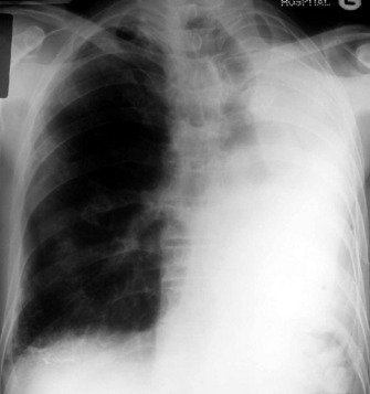
COMPLETE LUNG COLLAPSE
Complete collapse (Figure 35.12) will cause complete opacification of the hemithorax, with displacement of the mediastinum to the affected side and elevation of the hemidiaphragm. Compensatory hyperinflation of the contralateral lung with herniation across the midline may be apparent. Herniation may occur in the retrosternal space, anterior to the ascending aorta, or may be posterior to the heart.
INDIVIDUAL OR COMBINED LOBAR COLLAPSE
In any situation, some or all of the signs may be present.
Middle lobe collapse(Figure 35.14)
Right lower lobe collapse
Left upper lobe collapse (Figure 35.16)
COMBINED COLLAPSE
Right upper and middle lobe collapse is much less common because of the distance between the origins of their bronchi, and can generally be taken to imply the presence of more than one lesion. This combination will produce appearances almost identical to those of left upper lobe collapse (see Figure 35.16). On occasion isolated right upper lobe collapse will also produce appearances that are identical to left upper lobe collapse.
UNILATERAL INCREASED TRANSRADIANCY
ABNORMALITIES OF THE MEDIASTINUM
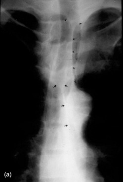
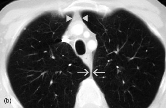
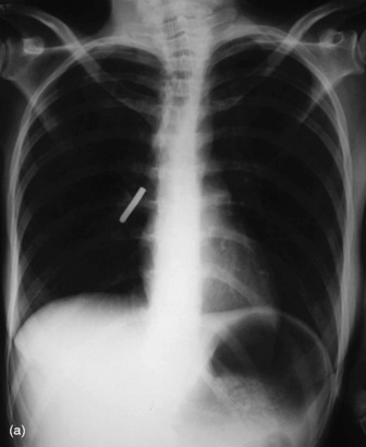
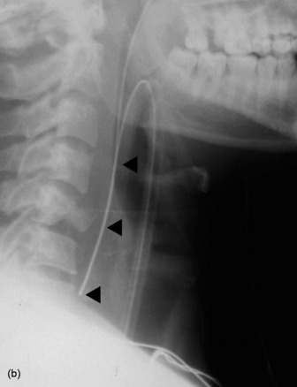
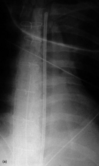
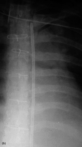
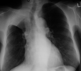
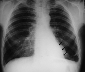
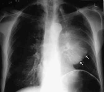
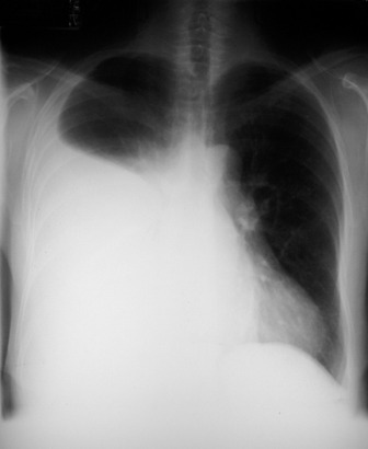
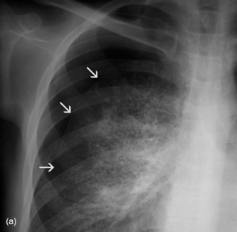
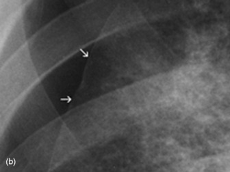
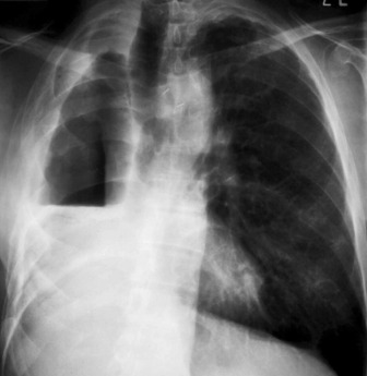
Mediastinal haemorrhage may occur from venous or arterial bleeding (Figure 35.17). The mediastinum appears widened, and blood may be seen tracking over the lung apices. It is imperative to identify a life-threatening cause such as aortic rupture.
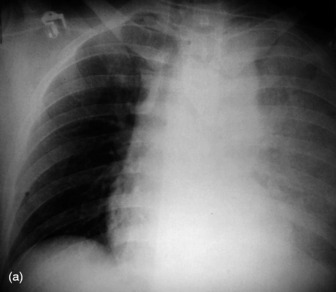
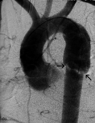
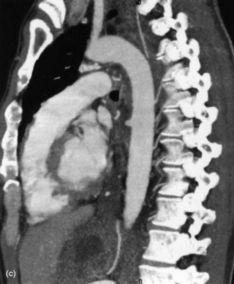
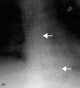
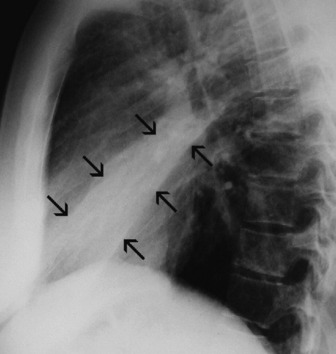
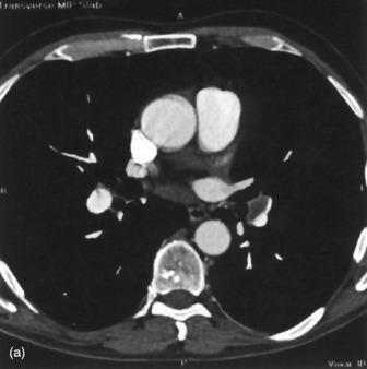
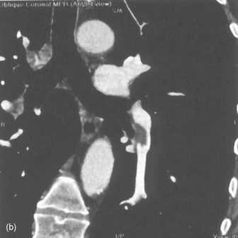
Figure 35.17 Aortic rupture. (a) There is opacification of the left hemithorax due to a large haemothorax which is layering posteriorly in this supine patient. There is widening of the mediastinum due to mediastinal haemorrhage. (b) Arch aortogram demonstrating widening of the descending thoracic aorta due to the aortic wall rupture. The point of return to normal calibre is demarcated by the arrows. (c) Computed tomography angiography of a different patient demonstrating a penetrating ulcer resulting in an aorto-oesophageal fistula that caused massive haematemesis. Note the local irregularity in the otherwise smooth anterior aortic wall on this oblique sagittal reformat.
PLEURAL FLUID
The most dependent recess of the pleural space is the posterior costophrenic angle and this is where a small effusion will tend to collect. As little as a few millilitres of fluid may be detected using decubitus views with a horizontal beam, ultrasound or CT. Larger volumes of fluid eventually fill in the costophrenic angle on the frontal view, and with increasing fluid a homogeneous opacity spreads upwards, obscuring the lung base (Figure 35.18). The fluid usually demonstrates a concave upper edge, higher laterally than medially, and obscures the diaphragm. Fluid may track into the fissures. A massive effusion may cause complete opacification of a hemithorax with passive atelectasis. The space-occupying effect of the effusion may push the mediastinum towards the opposite side, especially when the lung does not collapse significantly. Effusions in a supine patient redistribute into the paravertebral sulcus and produce an even increased density throughout that hemithorax.
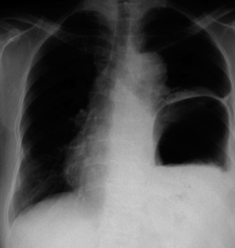
PNEUMOTHORAX
In an erect patient, air will usually collect at the apex (Figure 35.19). The lung retracts towards the hilum and on a frontal chest film the sharp white line of the visceral pleura will be visible, separated from the chest wall by the radiolucent pleural space, which is devoid of lung markings. This should not be confused with a skin fold, which mostly occurs in supine or recumbent patients. The lung usually remains aerated, although perfusion is reduced in proportion to ventilation and therefore the radiodensity of the partially collapsed lung remains relatively normal. A large pneumothorax may lead to complete retraction of the lung, with some mediastinal shift towards the normal side. Because it is a medical emergency, tension pneumothorax is often treated before a chest radiograph is obtained. However, if a radiograph is taken in this situation it will show marked displacement of the mediastinum. Radiographically the lung may be squashed against the mediastinum, or herniate across the midline, and the ipsilateral hemidiaphragm may be depressed. A supine pneumothorax may produce increased transradiancy towards the diaphragm, and a deep sulcus sign.
COMPLICATIONS OF PNEUMOTHORAX
Pleural adhesions may limit the distribution of a pneumothorax and result in a loculated or encysted pneumothorax (see Figure 35.8). The usual appearance is an ovoid air collection adjacent to the chest wall, and it may be radiographically indistinguishable from a thin-walled subpleural pulmonary cyst or bulla. Pleural adhesions are occasionally seen as line shadows stretching between the two pleural layers, preventing relaxation of the underlying lung. Rupture of an adhesion may produce a haemopneumothorax. Collapse or consolidation of a lobe or lung in association with a pneumothorax is important because they may delay re-expansion of the lung.
Since the normal pleural space contains a small volume of fluid, blunting of the costophrenic angle by a short fluid level is commonly seen in a pneumothorax. In a small pneumothorax this fluid level may be the most obvious radiological sign. A larger fluid level usually signifies a complication and represents exudate, pus or blood, depending on the aetiology of the pneumothorax. A hydropneumothorax is a pneumothorax containing a significant amount of fluid (Figure 35.20). On a radiograph obtained with a horizontal beam, a fluid level is evident. A hydro- or pyopneumothorax may arise as a result of a bronchopleural fistula, and may be a complication of surgery, tumour or infection.
PULMONARY EMBOLISM
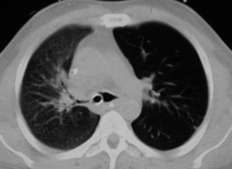
CT diagnosis of pulmonary embolism is becoming routinely available, and depends upon the ability to acquire, within a single breath-hold, a volume of data large enough to include the entire thorax. This rapid acquisition allows excellent contrast opacification of the pulmonary arterial tree for the duration of the scan, revealing any thrombus within the central pulmonary vessels (Figure 35.21). There are numerous studies evaluating helical and electron beam CT in the diagnosis of acute pulmonary embolus, with excellent reported sensitivity and specificity for the detection of clot down to the segmental level.5–8 Most of these studies also allow other diagnoses to be made that explain the symptoms of chest pain or dyspnoea, even when no pulmonary embolism is present.
TRAUMA AND THE ICU PATIENT
SKELETAL INJURY9
Following trauma rib fractures are common and may be single, multiple, unilateral or bilateral. In cases of chest trauma, the chest X-ray is more important in detecting a complication of rib fracture than the fracture itself. Fracture of one of the first three ribs is often associated with major intrathoracic injury, and fracture of the lower three ribs may be associated with important hepatic, splenic or renal injury. Complications of rib fracture include a flail segment, pneumothorax, haemothorax and subcutaneous emphysema. A flail segment is usually apparent clinically and radiologically. The fractured ends of ribs may penetrate underlying pleura and lung and cause a pneumothorax, haemothorax, haemopneumothorax or intrapulmonary haemorrhage. Air may also escape into the chest wall and cause subcutaneous emphysema. Fractures of the sternum usually require a lateral film or CT for visualisation. Fractures of the thoracic spine may be associated with a paraspinal shadow, which represents haematoma. Fractures of the clavicle may be associated with injury to the subclavian vessels or brachial plexus, and posterior dislocation of the clavicle at the sternoclavicular joint may cause injury to the trachea, oesophagus, great vessels or nerves of the superior mediastinum.
DIAPHRAGMATIC INJURY10
Laceration of the diaphragm may result from penetrating or non-penetrating trauma to the chest or abdomen. Rupture of the left hemidiaphragm is encountered more frequently in clinical practice than rupture on the right (Figure 35.22). The typical plain film appearance is of obscuration of the affected hemidiaphragm and increased shadowing in the ipsilateral hemithorax due to herniation of stomach, omentum, bowel or solid viscera, although such herniation may be delayed. Ultrasound may demonstrate diaphragmatic laceration and free fluid in both the pleura and peritoneum. Barium studies may be useful to confirm herniation of stomach or bowel into the chest.
PLEURAL INJURY9,11
Pneumothorax may be a complication of rib fracture, and is then usually associated with a haemothorax. If no ribs are fractured, pneumothorax is secondary to a pneumomediastinum, pulmonary laceration or penetrating chest injury. Pneumothorax due to a penetrating injury is liable to develop increased pressure, resulting in a tension pneumothorax, which may require emergency decompression. Haemothorax may also occur with or without rib fractures, and is due to laceration of intercostal or pleural vessels. If a pneumothorax is also present a fluid level will be seen on a horizontal-beam film. Pleural effusion may also result from trauma. Open injuries to the pleura are prone to infection and development of an empyema.
ACUTE AORTIC INJURY
Aortic rupture (see Figure 35.17)17 is usually the result of an automobile accident. Most non-fatal aortic tears occur at the aortic isthmus, the site of the ligamentum arteriosum. Only 10–20% of patients survive the acute episode, but a small number may develop a chronic aneurysm at the site of the tear. The commonest acute radiographic signs are widening of the superior mediastinum, and obscuration of the aortic knuckle. Other radiographic signs include deviation of the left main bronchus anteriorly, inferiorly and to the right, and rightward displacement of the trachea, a nasogastric tube or the right parasternal line. A left apical extrapleural cap or a left haemothorax may be visible. Although aortography is the definitive investigation, CT, transoesophageal echocardiography or magnetic resonance imaging may be diagnostic. In everyday practice, many departments will have emergency access to a CT scanner, but will not be centres of cardiothoracic surgery. A properly conducted CT scan demonstrating a normal mediastinum has a very high negative predictive value for aortic rupture. However, if CT is equivocal or shows a mediastinal haematoma then generally angiography will be required prior to surgery.
OESOPHAGEAL RUPTURE19
This is usually the result of instrumentation or surgery, but occasionally occurs in penetrating trauma, and is rarely spontaneous and due to sudden increase of intraoesophageal pressure (Boerhaave syndrome). Clinically there is acute mediastinitis; radiographically there are signs of pneumomediastinum, with or without a pneumothorax or hydropneumothorax, which is usually left-sided. The diagnosis should be confirmed by a swallow. This should initially be with water-soluble contrast medium in order to avoid the small risk of granuloma formation in the mediastinum that has been described following barium leakage. Chylothorax due to damage to the thoracic duct may become apparent hours or days after trauma. Thoracic surgery is the commonest cause.
THE POSTOPERATIVE CHEST
THORACIC COMPLICATIONS OF GENERAL SURGERY
THORACIC COMPLICATIONS OF CARDIAC SURGERY
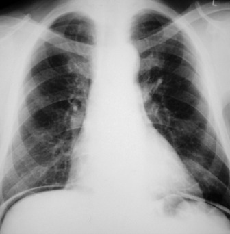
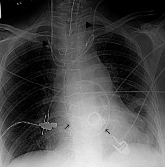
Widening of the cardiovascular silhouette is usual, and represents bleeding and oedema. Marked or progressive widening of the mediastinum suggests significant haemorrhage (Figure 35.23). Some air commonly remains in the pericardium following cardiac surgery, so that the signs of pneumopericardium may be present.
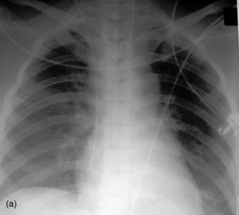
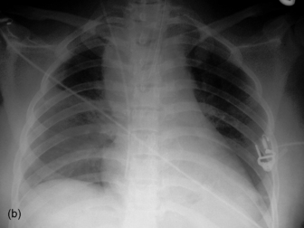
Figure 35.23 Following cardiac surgery (a) the postoperative chest radiograph appears satisfactory. A few hours later (b) the mediastinum has widened considerably, due to mediastinal haemorrhage.
Pneumoperitoneum is sometimes seen, due to involvement of the peritoneum by the sternotomy incision. It is of no pathological significance (see Figure 35.4).
1 Desai SR. Acute respiratory distress syndrome: imaging of the injured lung. Clin Radiol. 2002;57:8-17.
2 Chastre J, Trouillet J-L, Vuagnat A, et al. Nosocomial pneumonia in patients with acute respiratory distress syndrome. Am J Respir Crit Care Med. 1998;157:1165-1172.
3 Gillette MA, Hess DR. Ventilator-induced lung injury and the evolution of lung-protective strategies in acute respiratory distress syndrome. Respir Care. 2001;46:130-148.
4 Knutstad K, Hager B, Hauser M. Radiologic diagnosis and management of complications related to central venous access. Acta Radiol. 2003;44:508-516.
5 Task force report. Guidelines on the diagnosis and management of acute pulmonary embolism. Eur Heart J. 2000;21:1301-1336.
6 Monreal M, Suarez C, Fajardo JA, et al. Management of patients with acute venous thromboembolism: findings from the RIETE registry. Pathophysiol Haemost Thromb. 2004;33:330-334.
7 Baile EM, King GG, Muller NL, et al. Spiral computed tomography is comparable to angiography for the diagnosis of pulmonary embolism. Am J Respir Crit Care Med. 2000;161:1010-1015.
8 Wildberger JE, Mahnken AH, Das M, et al. CT imaging in acute pulmonary embolism: diagnostic strategies. Eur Radiol. 2005;15:919-929.
9 Wicky S, Wintermark M, Schnyder P, et al. Imaging of blunt chest trauma. Eur Radiol. 2000;10:1524-1538.
10 Eren S, Kantarci M, Okur A. Imaging of diaphragmatic rupture after trauma. Clin Radiol. 2006;61:467-477.
11 Miller LA. Chest wall, lung, and pleural space trauma. Radiol Clin North Am. 2006;44:213-224.
12 Nelson LD. Ventilatory support of the trauma patient with pulmonary contusion. Respir Care Clin North Am. 1996;2:425-447.
13 Wanek S, Mayberry JC. Blunt thoracic trauma: flail chest, pulmonary contusion, and blast injury. Crit Care Clin. 2004;20:71-81.
14 Keough V, Pudelek B. Blunt chest trauma: review of selected pulmonary injuries focusing on pulmonary contusion. AACN Clin Issues. 2001;12:270-281.
15 Kiser C, O’Brien SM, Detterbeck FC. Tracheobronchial injuries: treatment and outcomes. Ann Thorac Surg. 2001;71:2059-2065.
16 Ketai L, Brandt MM, Schermer C. Nonaortic mediastinal injuries from blunt chest trauma. J Thorac Imaging. 2000;15:120-127.
17 Mirvis SE. Diagnostic imaging of acute thoracic injury. Semin Ultrasound CT MR. 2004;25:156-179.
18 Bansal MK, Maraj S, Chewaproug D, et al. Myocardial contusion injury: redefining the diagnostic algorithm. Emerg Med J. 2005;22:465-469.
19 Younes Z, Johnson DA. The spectrum of spontaneous and iatrogenic esophageal injury: perforations, Mallory–Weiss tears, and hematomas. J Clin Gastroenterol. 1999;29:306-317.