Imaging and interventional techniques in surgery
Plain radiology
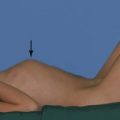
Some foreign bodies in wounds are radiopaque, including metal and most glass fragments, but wood and plastic are radiolucent and invisible. Gauze swabs used in operating theatres are radiolucent but have a radiopaque strand allowing them to be located radiographically if left in a wound (Fig. 5.1).
Case History
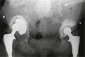
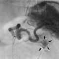
Fig. 5.1 Plain abdominal X-ray showing retained surgical swab
This 83-year-old woman had persistent pain in the left iliac fossa after a left hip replacement. This pelvic X-ray was taken to investigate the new joint. However, a radiopaque marker was spotted (arrowed) indicating a surgical swab that had been left in the abdomen after a laparotomy for perforated duodenal ulcer 8 years previously. The swab was removed uneventfully at a second laparotomy
Personal radiation protection
• Giving training in radiation protection to all staff using and working near X-ray equipment
• Ensuring every investigation helps with management and none is performed merely as ‘routine’
• Improving design of X-ray equipment to minimise radiation dose whilst preserving diagnostic detail. X-ray scatter is minimised and unwanted types of radiation removed by filters
• Physical barriers are built into radiology suites or provided to protect staff. These include barium plaster in walls, lead-glass windows and lead-rubber aprons
• Workers involved in X-rays should keep away from the direct beam line and maintain a good distance from the X-ray source during exposure. Note the inverse square law determines the fall-off of radiation with distance
• All involved in radiography should wear X-ray-sensitive film badges which need to be regularly monitored for excess radiation
General Principles of Radiology
These factors are involved in producing a useful radiographic image:
• X-ray power and exposure time—chosen to give a diagnostically useful exposure without excess dosage. Good quality images have a range of densities appropriate to the anatomical area. For example, thoracic spine views require a larger dose than lungs
• Different projections (views) produce different views of the same subject. The X-ray tube is effectively a point source with a diverging beam (see Fig. 5.2), so the subject is magnified. The distortion least affects the body part closest to the film, which is thus shown most clearly. The beam direction should be recorded on the film as it has consequences for interpretation, e.g. a frontal chest film might be PA (postero-anterior) or AP (antero-posterior). With lateral exposures, the side nearest the film is indicated, e.g. a ‘Rt’ lateral chest X-ray (CXR) has the right side nearest the film
• Patient position during exposure (i.e. supine, prone, oblique or erect) affects the image because of gravity affecting organs, gas or fluid. Most films are taken with the patient lying supine with the X-ray beam aimed vertically downwards. A horizontal beam can demonstrate fluid levels in a cavity or bowel (lateral decubitus), or free gas under the diaphragm
Electronic recording techniques
• Substantial cost saving on film and processing chemicals
• Reduced physical space needed for storage
• Reduced staff costs—no need to file or retrieve films
• Better availability of images—no need to obtain physical films; several viewers can see the same images simultaneously in their place of work
• Substantially reduced numbers of missing examinations
• Easy transmission of images from one institution to another—by portable storage media (CD-ROM) or electronic links
‘Filmless’ X-ray departments are becoming the norm, with images displayed on terminals dispersed around the hospital. Images can be accessed remotely by family practitioners and clinicians at home or in other hospitals.
Plain radiology
Chest X-ray: Interpreting plain chest X-rays requires a methodical approach. Several learned documents have been written on the subject (see e.g. http://student.bmj.com/student/view-article.html?id=sbmj04018), and no attempt will be made to produce an incomplete version here.
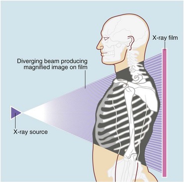
Plain abdominal radiology: Most abdominal films are taken with the patient supine. Bowel is visible when it contains gas (Figs 5.3 and 5.4); normal small bowel is less than 3 cm wide and tends to occupy the centre of the abdomen. When dilated, it shows transverse folds (plicae circulares) which completely cross the lumen. The colon usually lies peripherally and has haustrations; these folds only partly traverse the lumen (Fig. 5.3). Normal colon is less than 6 cm wide and often contains faecal lumps with a mottled appearance. Further reading about this topic is available from: http://www.studentbmj.com/topics/clinical/imaging_techniques.php.
Case History
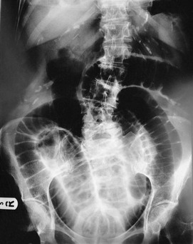
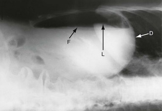
Fig. 5.4 Abdominal X-ray
This 78-year-old woman presented with a sudden onset of severe abdominal pain. Erect chest X-ray failed to show free abdominal gas but a perforation was clinically suspected so this lateral decubitus X-ray was performed. The right side is raised and the head is to the right of the picture; the X-ray beam was horizontal. Free intraperitoneal gas is seen above a fluid level F beneath the diaphragm D and ‘floating’ over the liver L. At laparotomy, the cause proved to be a perforated duodenal ulcer
When examining an abdominal X-ray, important features to look for are:
• Calcification in areas prone to stone formation, e.g. kidney, ureters, bladder or biliary tree (see below, Urography, Fig. 5.8a)
• Dilated bowel (stomach, small or large bowel)
• Free intraperitoneal gas indicating bowel perforation
• Gas in abnormal places (e.g. biliary tree or urinary tract) suggesting a fistula with bowel
• Non-biological objects, e.g. foreign bodies, surgical tubes or pieces of metal
• Pathological calcification, e.g. aortic aneurysm, pancreas, adrenals or uterine fibroids
The limitations of plain abdominal radiography are summarised in Box 5.1.
Free intraperitoneal gas: Free gas is diagnostic of bowel perforation except after recent laparotomy. A horizontal beam chest or upper abdominal X-ray with the patient erect is the most useful method of demonstrating it as a radiolucent layer beneath the diaphragm (see Fig. 19.8, p. 275). The layer can be very small but is often obvious. Perforation can also be confidently diagnosed when the inside and outside of the bowel wall are both outlined by radiolucent shadows, but this is rare (Rigler’s sign, Fig. 32.7, p. 413). Where the result is doubtful or the patient too ill to sit or stand, he or she should be placed in the right-side raised lateral decubitus position (i.e. lying on the left side) for 10 minutes. A horizontal beam X-ray taken across the table can then reveal as little as 2 ml of gas above the lateral liver border (Fig. 5.4).
Bone X-rays: Conventional radiographs of bones continue to play an important role in diagnosis of bone disease, particularly fractures, but also infection, neoplasia and degenerative conditions. Other investigations including bone scintigraphy, CT, MRI and ultrasound are often used, particularly if conventional X-rays are normal. If in doubt it is best to discuss with a radiologist.
Contrast radiology
Contrast materials: Barium sulphate is the best agent for directly outlining the GI tract. It is insoluble in water and is not absorbed. An aqueous suspension is non-irritant and very radiodense. Barium investigations of the upper and lower gastrointestinal tracts have been largely superseded by endoscopy or cross-sectional imaging but are still occasionally employed.
Examples of contrast radiology:
Bowel contrast radiology: Any part of the gastrointestinal tract can be demonstrated using contrast. Most barium studies use a double contrast method. Following barium, air or carbon dioxide is used to distend the bowel and separate the barium-coated bowel walls. An anticholinergic agent such as hyoscine butylbromide (Buscopan) is sometimes given at the same time to abolish spasm, further improving the image.
Preparation for bowel contrast studies: For upper gastrointestinal studies, patients should be fasted overnight except for water. For a barium enema, bowel preparation is performed with laxatives (e.g. sodium picosulphate) and sometimes bowel washouts, so artefacts are removed (faecal lumps look similar to polyps) and small mucosal defects are not obscured.
Upper gastrointestinal tract: For examining the upper GI tract, barium suspension is given orally (barium swallow for oesophagus and barium meal for stomach and duodenum. Progress of contrast is observed by screening, with a moving image displayed on a screen. The radiologist usually selects representative spot films to summarise the examination. Screening is useful to study rapid GI motility as in swallowing; images can be studied later in slow motion.
Large bowel: The large bowel is examined by means of contrast material given rectally (barium enema). The lower rectum is often poorly shown so prior rectal examination and sigmoidoscopy is best to ensure low lesions are not missed.
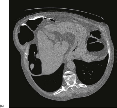
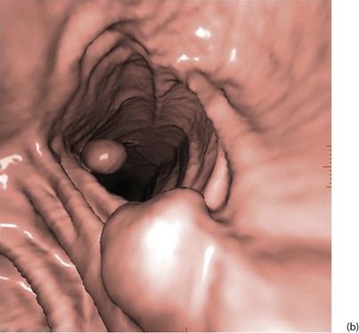
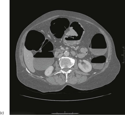
With improved technology, CT is increasingly used for large bowel examination. It can be performed without laxative preparation where it would be acceptable to miss small polyps, for example in suspected obstructing lesions. CT can be useful in the frail elderly when a right-sided colonic cancer is suspected because of anaemia or a palpable mass. For a more complete examination, CT colonography (also known as CT coloscopy or virtual colonoscopy) requires full bowel cleansing. During the procedure, air or carbon dioxide is insufflated into the colon; the technique is sensitive enough to detect lesions larger than 1 cm. The investigation is quicker and less unpleasant than barium enema and has replaced it altogether in some units. Hundreds of images are produced and the best are viewed on workstations along with reconstructed axial and 3D images of the bowel lumen (see Fig. 5.5).
Small bowel: For small bowel examination, a barium meal may be ‘followed through’ into the small bowel, or contrast can be instilled directly into the proximal jejunum via a nasal or oral tube. In either case, the diagnostic yield is poor and these techniques are likely to be replaced by CT or MR studies of the small bowel or capsule endoscopy (see below).
Complications of barium contrast studies: The limitations of barium contrast studies are summarised in Box 5.2. There is a risk that contrast material may be aspirated into the bronchial tree, causing aspiration pneumonitis, so care must be taken when giving oral barium to patients with swallowing difficulties. CT scanning is safer and more likely to provide useful information such as the level and cause of obstruction, and associated pathology such as lung or liver metastases.
Some biliary investigations described in previous editions of this book (e.g. oral cholecystography and intravenous cholangiography) have been superseded by ultrasound and increased availability of endoscopic retrograde cholangio-pancreatography (ERCP, p. 65) and magnetic resonance cholangio-pancreatography (MRCP).
Magnetic resonance cholangio-pancreatography (MRCP) (Fig. 5.6 e and f): MRCP now produces images that rival the quality of ERCP. MRI differentiates tissues and organs by their varying water content. Bile and pancreatic juice are mostly water, hence MRCP gives clear images of bile in the gall bladder and ducts and outlines the pancreatic duct. It reveals filling defects caused by stones or tumours. MRCP can identify bile leaks, gallstones in the bile ducts, and duct obstruction from any cause. There are no known hazards. MRCP is increasingly used prior to ERCP for pancreatico-biliary investigation to reduce the number of patients requiring the more invasive investigation.
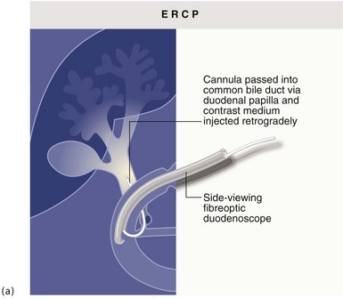
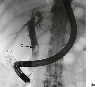
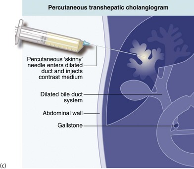
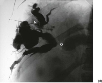
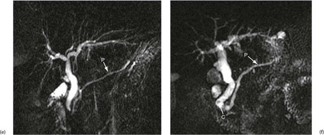
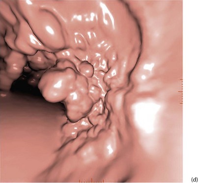
Fig. 5.6 Some techniques for demonstrating the biliary system
(a) and (b) Endoscopic retrograde cholangiography
The patient is sedated and a side-viewing gastroscope passed down so the tip reaches the second part of the duodenum. The ampulla of Vater is cannulated under direct vision and contrast medium injected to outline the bile ducts. (b) A large gallstone C is seen within the dilated common bile duct and a collection of radiopaque gallstones GS is seen in the gall bladder
(c) and (d) Percutaneous transhepatic cholangiography
A needle N is passed into the liver until it encounters a dilated duct. Contrast medium is then injected to outline the ducts. (d) Case study—this deeply jaundiced 57-year-old woman has grossly dilated intrahepatic ducts and complete obstruction of the proximal common bile duct in the porta hepatis at O. This was due to lymph node metastases from carcinoma of stomach. This method is employed less often nowadays because of the superior safety of other methods described here
(e) and (f) Magnetic resonance cholangio-pancreatography (MRCP)
The technique produces images of static fluid, thus the images are of native biliary and pancreatic secretions. Each image was obtained in one second using a thick slab ‘projection’ method that generates images very similar to ERCP. The pancreatic duct in each image is labelled P. (e) An example of normal biliary and pancreatic duct systems. (f) A small calculus, C, in the distal common bile duct. There is also mild dilatation of the pancreatic duct with some side branches visible
• Suspected bile duct stones, especially within the liver and for seeking retained stones after operation
• Bile duct strictures, particularly within the liver—post-surgical, cholangiocarcinoma
• Suspected sclerosing cholangitis
• Acute pancreatitis of unknown aetiology—MRCP reveals anatomical duct abnormalities
• Biliary-type pain with abnormal liver function tests in patients without stones on ultrasound
• Patients unsuitable for ERCP because they are intolerant of the procedure or have had previous gastrectomy
Percutaneous transhepatic cholangiography (PTC): Percutaneous cholangiography is rarely used for diagnosis but has occasional therapeutic indications. A long fine (22 G) ‘Chiba’ needle is passed percutaneously, directly into dilated intrahepatic ducts, and contrast injected to display the duct system (see Fig. 5.6c). This shows the configuration of extrahepatic duct obstruction from the proximal direction. Occasionally, PTC is employed to drain obstructed ducts after failed endoscopic placement of a drain or stent. In jaundiced patients, disordered blood clotting is likely so a clotting screen and platelet count should be performed before PTC, and any clotting disorder corrected.
Endoscopic retrograde cholangio-pancreatography (ERCP): This is described below (see Diagnostic and therapeutic duodenoscopy); its use in obstructive jaundice is described in detail in Chapter 18. The basic technique is illustrated in Figure 5.6 a and b.
Operative cholangiography and choledochoscopy: It is standard practice to perform operative cholangiography during open cholecystectomy. For laparoscopic cholecystectomy, some surgeons routinely perform operative cholangiography whilst others prefer no imaging at all for selected cases or else preoperative assessment using MRCP for cases deemed likely to have duct stones.
T-tube cholangiography: Following exploration of bile ducts for stones, a T-tube is often left in situ to drain the duct. The transverse limb of the T lies in the duct and the long limb drains out through an opening in the duct to the skin where it is connected to a drainage bag. About 1 week after operation, contrast can be injected along the T-tube to outline the biliary tree and show abnormalities such as residual stones, bile leakage and duct stenoses as well as confirming free drainage into the duodenum. If residual stones are still present they can be retrieved either at ERCP or sometimes by the radiologists via the T-tube itself.
Vascular Radiology (Angiography)
General principles and hazards of arteriography and venography
Further detail about applications of vascular radiology is given in Chapter 41.
The contrast medium is the same as that used for computed tomography (CT) and carries similar hazards, i.e. allergic reaction and nephrotoxicity (see Urography below). There is also the risk of complications from the cannulation, which may cause bleeding or thrombosis and, for arteries, wall dissection, arteriovenous fistula or false aneurysm formation.
Endovascular techniques
Percutaneous transluminal angioplasty (PTA) or balloon angioplasty: Angioplasty under local anaesthesia is a less invasive alternative to surgery for treating many peripheral and coronary arterial stenoses. In general, short stenoses in large vessels are most suitable. The method is particularly useful for lower limb atherosclerosis (especially iliac and superficial femoral arteries) and for coronary artery disease and, to a lesser extent, renal artery and mesenteric artery stenoses. Carotid artery disease is also suitable for angioplasty in some cases; filters are usually placed above the stenotic segment before dilatation to reduce the risk of embolism to the brain.
Techniques of percutaneous angioplasty: Angioplasty is usually performed under local anaesthesia (Fig. 5.7). A needle is first inserted into an accessible artery and a short flexible guide-wire passed through it into the artery and the needle removed. A working sheath with a valved side-arm is passed over the guide-wire and advanced into the artery. A catheter is inserted and a long guide-wire is then substituted for the first and manipulated up to and through the stenosis using contrast injections and fluoroscopic control. An angioplasty catheter with a plastic inflatable balloon at its end is then passed over the guide-wire and manipulated across the stenosis. Angioplasty balloons are now no wider than the catheter before inflation, and inflate to a fixed diameter at a given pressure. It is possible to measure the arterial pressure above and below the stenosis to determine the pressure gradient before and after angioplasty, although this is not performed routinely. The balloon is then inflated to a pressure of typically 6 and 15 atmospheres, depending on the balloon type, to dilate the stenosis, then further contrast is injected to check the result. Angioplasty techniques and equipment have progressively improved and many patients now return to near-normal life after minimal intervention.
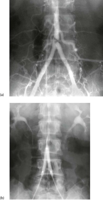
Fig. 5.7 Percutaneous transluminal angioplasty
This man of 55 presented with bilateral calf and thigh claudication. (a) A localised severe stenosis of the distal abdominal aorta. (b) The ‘kissing balloon’ technique used to dilate the stenosis. Two balloons, shown inflated, are used to prevent asymmetrical dilatation which might compromise the opposite common iliac artery
Local arterial thrombolytic therapy: An artery freshly occluded by thrombosis and causing ischaemia can be recanalised by local intra-arterial infusion of thrombolytic agents. High local concentrations with limited systemic spill-over were intended to avoid the serious bleeding and allergic complications of systemic thrombolysis. However, experience has shown that the risk of major haemorrhage still exists, some episodes of which have been fatal. Examples include intracerebral haemorrhagic strokes and bleeding from recent surgical wounds or from the gastrointestinal tract. For this reason, the treatment has limited indications, i.e. recently occluded native arteries or bypass grafts. The thrombolytic agent usually used is recombinant tissue plasminogen activator (R-tPa). R-tPa acts more quickly and does not have the frequent allergic effects of the older agents, e.g. streptokinase.
For recent acute embolic ischaemia, surgical embolectomy remains the best treatment.
Therapeutic embolisation: Highly vascular lesions that would be difficult or impossible to treat by surgery alone, such as some arteriovenous malformations, can have their arterial supply reduced or obliterated by embolisation. The main supplying artery is identified by selective arteriography and a catheter manoeuvred into it, close to the lesion. The materials chosen for embolisation depend on the nature of the lesion but include gelatin foam, polyvinyl alcohol particles, minute steel coils, plugs, cyanoacrylate glue or liquid polymers. The process can be repeated for all the feeding vessels.
Minimal access graft placement: EVAR is now widely used to treat both abdominal and thoracic aortic aneurysms. There are several different devices available, composed of metal stents and graft material, and technical improvements are continuing. The device is correctly positioned in the aorta, and then deployment consists of unsheathing the device under fluoroscopic guidance. Graft limbs are used to extend the device into the iliac arteries. There are now stent grafts capable of treating more complex aneurysms with side branches/grafts into the renal, mesenteric, internal iliac or arch arteries. One disadvantage of the technique includes endoleakage, i.e. continued slow bleeding into the aneurysm sac because of an inadequate seal or, more commonly, from lumbar arteries or the inferior mesenteric artery. Other complications include graft migration, limb occlusion or limb dislocation. Although reintervention rates are higher than with open aneurysm repair, these techniques have allowed many patients to be treated who would never be fit for open surgery. The late complication rate is about 10% per year, considerably greater than for open aneurysm grafting, but rates are falling with improving techniques.
Venous techniques
Venography: Colour duplex Doppler ultrasound scanning has replaced contrast venography for diagnosing deep vein thrombosis (DVT) as well as for demonstrating reflux from deep to superficial vessels in varicose veins. A skilled operator can demonstrate the patency or otherwise of all the lower limb veins and the presence of fresh or old thrombus. Valve competence can be shown in deep and superficial veins and perforating veins. Vein wall irregularity caused by previous DVT can also be displayed. Contrast venography can sometimes be helpful in defining the anatomy of complex superficial varicose veins and very occasionally to diagnose or exclude calf vein DVT where duplex is inconclusive.
Placement of vena caval filters: After venous thromboembolism, a few patients experience recurrent pulmonary embolism despite adequate anticoagulation. In others, anticoagulation therapy is contraindicated and other methods of preventing pulmonary embolism must be found, e.g. in pregnancy, after a haemorrhagic stroke, in patients with a high risk of falling or those with certain bleeding disorders. In these groups, the risk of pulmonary embolism can be markedly reduced by placing a filter in the inferior vena cava, above or below the renal veins. This still allows venous blood to return to the heart but traps substantial embolic material in the flowing blood. Since the mid-1960s a range of filtration devices have been developed that can be inserted relatively simply using a catheter via the femoral or jugular vein. Typical examples are the Celect or Optease filter. Some filters can be retrieved by percutaneous techniques if necessary within a limited time period. Complications are uncommon and include caval occlusion, migration and strut fracture.
Urography
General principles of urography: Urography is a radiological technique for examining the kidneys and urinary collecting systems using intravenous contrast concentrated and excreted by the kidneys. A plain abdominal control film is taken beforehand so calcified opacities can be compared with post-contrast images. This helps identify if an opacity lies within the renal tract and hence whether it is likely to be a stone (see Fig. 5.8a).
Fig. 5.8 Plain abdominal X-ray and IVU compared
(a) A plain abdominal film and (b) an intravenous urogram (IVU) of the same patient showing urinary tract stones. In the plain film, several calcified opacities (arrowed) are seen. From the IVU, in which the pelvicalyceal systems and ureters contain contrast material, it can be seen that three stones A lie within the lower right ureter and stone B lies within the upper calyces of the left kidney. On the right side, two other opacities C are seen to lie outside the urinary tract, probably representing calcified lymph nodes in the small bowel mesentery
Special precautions with intravenous urography: Intravenous contrast is potentially nephrotoxic in patients with impaired renal function. Risk factors should be specified to help the radiologist plan the safest investigation. Alternatives such as ultrasound, unenhanced CT or occasionally MR may be considered. Important risk disorders are:
CT urography: Unenhanced CT of the renal tract is increasingly used instead of IVU to diagnose renal or ureteric colic. It is more sensitive for detecting stones and is quicker to perform but usually gives a higher radiation dose. CT with intravenous contrast is frequently used to investigate persistent haematuria when other tests are normal; in some centres, it is used earlier in the diagnostic pathway.
Percutaneous therapeutic techniques: The renal pelvis can be punctured percutaneously with a needle guided by ultrasound or CT scanning. The tract is then dilated to allow tubes of various types and sizes to be inserted. Gaining access to the kidney in this way is known as percutaneous nephrostomy. It can be employed to remove stones from the renal pelvis, to urgently but temporarily relieve acute distal urinary obstruction and drain the kidney over a few days ahead of a definitive procedure.
Medical Ultrasound
General principles of medical ultrasound
Bone, stones and other calcified tissues cause an abrupt and marked change in acoustic impedance, giving complete reflection of ultrasound. Thus the surface of hard tissue such as gallstones is revealed by the acoustic shadow it casts (see Fig. 20.4, p. 285). A smaller change in acoustic impedance occurs at gas/soft tissue interfaces such as bowel wall and its gas-filled lumen.
Special transducers: Probes have been developed for use via different body orifices, and for body cavities via endoscopic instruments, percutaneous cannulae and laparoscopes. These devices are placed closer to the structures being examined than surface probes. This allows higher-frequency sound to be used which has lower penetration but greater spectral resolution and gives a more detailed display. These transducers are often combined with biopsy devices to enable tissue sampling.
Applications of ultrasound in general surgery
• Reliably distinguishing solid from cystic lesions, e.g. a thyroid cyst from solid nodule, renal or pancreatic cyst from solid tumour
• Assessing palpable abdominal masses in the upper abdomen or pelvis
• Detecting abnormal tissues in a homogeneous organ, e.g. liver metastases or renal adenocarcinoma
• Detecting damage to solid organs after trauma, e.g. splenic or liver rupture
• Detecting abnormal fluid collections, e.g. pseudocyst of pancreas, ascites, pleural effusions, abscesses
• Assessing the nature of lesions from the way the echo texture contrasts with the normal, e.g. distinguishing liver secondaries from benign lesions or normal liver
• Detecting movement, such as pulsation of an aneurysm, contraction of the heart (echo shows valve morphology and movement, ventricular wall movement), and fetal anatomy and movement
• Detecting upper urinary tract dilatation (hydronephrosis)
• Measuring physical dimensions, e.g. the diameter of an abdominal aortic aneurysm or a dilated bile duct, or the volume of residual urine in the bladder after micturition
• Investigating the biliary system for gallstones, thickened gall bladder wall, dilated ducts, masses in the head of the pancreas or porta hepatis
• Guiding percutaneous interventional procedures for tissue sampling, e.g. aspiration or biopsy of liver metastases, pancreatic tumours or retroperitoneal masses, or drainage of fluid collections
• Investigating breast lumps, e.g. distinguishing cystic from solid lesions, suspected malignant lesions, guided cyst drainage, guiding fine-needle aspiration (FNA) for cytology, or core biopsy
The limitations of diagnostic ultrasound are summarised in Box 5.3.
Doppler-shifted ultrasound: Ultrasound can detect and study blood flow by applying the Doppler principle. Simple hand-held equipment is cheap and portable, and is invaluable in the vascular clinic (see Fig. 5.9). Using a probe coupled to the skin with conduction gel, a beam of ultrasound is directed at an artery or vein. Ultrasound reflects from moving red cells and causes a shift in sound frequency related to blood velocity. Reflected ultrasound is used to generate an audible signal (for detecting blood flow) or is processed to reveal information about the nature of flow. The audio pitch is related to blood velocity and provides some qualitative assessment of whether flow is normal or abnormal.
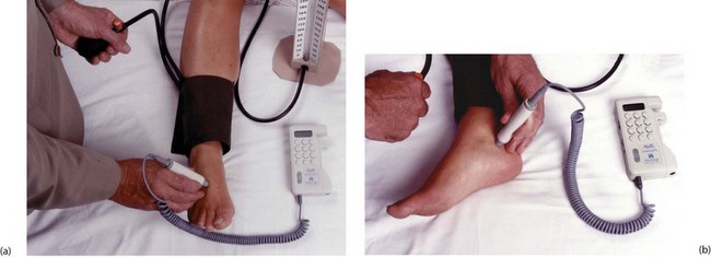
Fig. 5.9 Measuring ankle systolic pressure using a hand-held Doppler flowmeter
(a) A standard sphygmomanometer cuff is placed around the ankle just above the malleoli. Ultrasound conducting gel is applied to the tip of the probe and the probe placed lightly over the likely position of the dorsalis pedis (DP) pulse, between the first two metatarsals. The probe is moved a tiny amount at a time so as to obtain the strongest signal, then the cuff is inflated until the pulse disappears. The cuff is then released gradually and the systolic pressure recorded at the point of return of signal. (b) The same process is repeated at the posterior tibial pulse (PT), using the midpoint of a line between the heel and the medial malleolus to find the pulse. Note that accurate measurements require considerable experience, especially when the pressure is low. Headphones are recommended to reduce interference
Main applications of hand-held Doppler ultrasound:
• Measuring systolic blood pressure when it is low. This includes brachial pressure in shocked patients or in infants, and ankle systolic pressures in lower limb ischaemia. For this, a sphygmomanometer cuff is placed around the arm or ankle and a flow detector is applied to an artery beyond the cuff (Fig. 5.9)
• Simple detection of venous blood reflux at the sapheno-femoral or sapheno-popliteal junction in varicose veins, particularly if recurrent
Duplex Doppler ultrasound scanning: Duplex Doppler scanning combines frequency spectral analysis of blood flow using Doppler ultrasound with 2D imaging of the vessel. Colour flow Doppler adds false colour to show the direction of blood flow and gives qualitative information about flow volume.
Applications of duplex Doppler:
• Deep vein thrombosis—this is the method of choice for detecting postoperative DVT. Thrombus more than 24 hours old can be seen and venous flow changes detected. However, the profunda vein and small calf veins are often poorly seen
• Chronic lower limb deep venous insufficiency—patency and valvular competence in deep veins (e.g. femoral and popliteal) can be determined dynamically; perforator incompetence can also be detected
• Varicose veins—duplex ultrasound is useful for detecting and guiding marking of the short saphenous/popliteal junction before operation and for detecting communications between superficial veins and the sapheno-femoral junction in ‘recurrent’ long saphenous varicose veins. There are advantages to performing ultrasound in all varicose vein patients before treatment to clarify the diagnosis
• Carotid artery disease—duplex has now become the standard test for investigating extracranial vascular disease in preference to carotid angiography (which carries distinct risks). Duplex shows the morphology of diseased arteries and the velocity of flow, allowing the percentage of stenosis to be calculated. The severity of stenosis determines whether operation is required. Duplex is useful for evaluating asymptomatic bruits and following up patients after carotid endarterectomy, including in the early postoperative period
• Femoro-popliteal bypass grafts—duplex is used for marking out the saphenous vein graft before surgery and for graft surveillance after surgery to detect remediable vein graft stenoses
• Aorto-iliac and femoro-popliteal occlusive disease—duplex is proving valuable for estimating the sites and severity of stenoses and occlusions and replaces arteriography in some circumstances
• Deeper blood vessels—these can be imaged for blood flow and obstruction, e.g. superior mesenteric and renal arteries, and renal veins for spread from renal cell carcinoma
• Cardiac disease—echocardiography is used for detecting abnormal anatomy and function including heart failure, ventricular dysfunction, valvular abnormalities including stenoses, congenital cardiac defects including septal defects, and intracardiac abnormalities predisposing to embolism
Cross-Sectional Imaging
Computerised tomography (CT scanning)
General principles of CT scanning: Computerised tomography involves X-raying a series of thin transverse ‘slices’ of the patient’s head, body or limbs. A precise fan-shaped beam of X-rays is repeatedly pulsed from successive angles around the circumference of each slice and the transmitted radiation is electronically recorded on the opposite side (see Fig. 5.10).
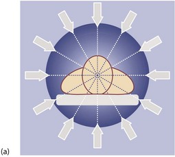
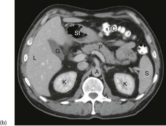
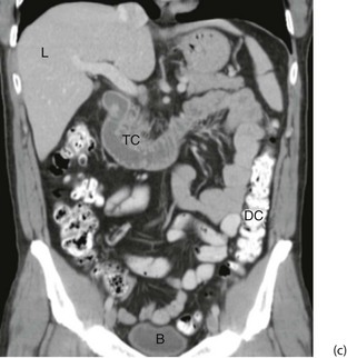
Fig. 5.10 Computerised tomography
(a) Principle of CT scanning. All images are fed into a computer and a single image of each slice produced. (b) Normal transverse CT scan. Liver L, gall bladder G, stomach St, kidneys K, aorta A, pancreas P, spleen S. (c) Normal CT scan reconstructed in the coronal plane. Liver L, bladder B, transverse colon TC, descending colon DC
Applications of CT scanning: Pathological anatomy can be studied in great detail and a huge array of information can be obtained non-invasively to assist surgical diagnosis. Often the information is more accurate than could be obtained by exploratory operation. This is outstandingly so in brain injury after trauma where the management of serious head injuries has been transformed by head scanning. The technique enables timely and appropriate surgical intervention and avoids unnecessary exploratory operations.
Some indications for CT scanning are:
• Investigating areas difficult to examine by standard radiology or ultrasound. Examples include the retroperitoneal area and pancreas (deep inside the body), the lungs and mediastinum, and the brain and spinal cord (encased in bone)
• Investigating acute abdominal pain—early CT misses fewer serious diagnoses and may reduce mortality and shorten hospital stay (see below)
• Investigating abdominal pathology when ultrasound has proved unsatisfactory or as an alternative to more intrusive investigations such as barium enema for suspected large bowel disorders
• Pretreatment planning and follow-up of malignant tumours being treated with radiotherapy and/or chemotherapy, e.g. for staging lymphomas (replaces laparotomy)
• Planning surgery, e.g. establishing the extent of local invasion of oesophageal carcinoma, identifying the upper level of an aortic aneurysm, investigating the extent of lateral spread in rectal or prostatic cancer, preoperative assessment of intrathoracic tumours including retrosternal thyroid enlargement
• Assessing solid organ damage in abdominal or thoracic trauma
• Guiding needles during biopsy of masses, drainage of fluid collections or obtaining aspiration cytology specimens
• Diagnosis of pulmonary embolism, renal tract calculi and arterial disease. Multislice CT has now also developed to a stage where it can often replace diagnostic coronary arteriography
Magnetic resonance imaging (MRI)
Principles of magnetic resonance imaging: Magnetic resonance imaging (MRI) was introduced into clinical practice in the early 1980s. MRI involves applying a powerful magnetic field to the body which causes the protons of hydrogen nuclei to become aligned. The protons are then excited by pulses of radio waves transmitted at a frequency that causes them to resonate and emit radio signals; these are recorded electronically. Sophisticated computation then produces images which can be viewed in any plane, transversely, longitudinally or at any obliquity (see Fig. 5.11).
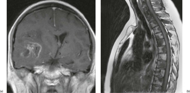
Fig. 5.11 Magnetic resonance images
(a) Gadolinium enhanced T1-weighted coronal MRI of the brain. Note enhancement of a tumour T, midline shift with compression of the right lateral ventricle L. The falx F and third ventricle 3 are also labelled. (b) T1-weighted sequence sagittal MRI of the thoracic spine in a patient with known prostate cancer, back pain and an elevated prostate specific antigen. The image demonstrates bony metastases as dark areas in the vertebral bodies and spines; the white areas are normal fat in the marrow
Disadvantages of MRI: Some patients are unable to tolerate MRI because of claustrophobia but the main technical drawback is the effect of magnetism on metal. Thus metallic foreign bodies, especially in the eyes, may move in the magnetic field and cause damage. MRI cannot be used with cardiac pacemakers and some metallic implants, and patients being artificially ventilated require machines made of non-ferrous materials. Scanning times are still longer than for CT (though falling) and so MRI is less suitable for young children, the elderly or confused, patients in pain, ventilated patients and emergency patients with active bleeding. The diagnostic applications of MRI continue to expand in parallel with the technical improvements.
Applications of magnetic resonance imaging:
General surgical diagnosis: MRI is especially useful for assessing soft tissue tumours, biliary anatomy and pelvic disease. For soft tissue tumours of the extremities, MRI is valuable in planning surgery. It can demonstrate the true extent of the tumour and its relationship to vital structures, so excision margins can be decided before operation.
Blood flow: An exciting development is the ability to demonstrate blood flow in the heart and blood vessels, i.e. magnetic resonance angiography (MRA). Blood vessels can be visualised without need for contrast injection and abnormalities detected as in conventional angiography. In addition, volume flow can be calculated in particular vessels. Spatial resolution can be improved by injecting paramagnetic materials such as compounds containing gadolinium. MRI is playing an escalating role in diagnosing cardiac and arterial disease and may in time replace diagnostic coronary angiography.
Interventional Radiology
Tissue sampling
Fine-needle aspiration cytology (FNA) and core biopsy: A fine needle (22 gauge) can be safely passed through most organs or small bowel to aspirate fragments of tissue from a suspicious lesion. Larger-diameter needles can be used for direct core biopsy of masses. The depth and direction of the needle can be accurately guided by ultrasound or CT to ensure a representative sample is taken. For example, pancreatic masses can be reached by transfixing bowel lying in front of the pancreas; this causes remarkably few side-effects. Where practicable, many surgeons and pathologists prefer the larger specimens obtainable with core biopsy techniques using special needles such as the Trucut, available in various configurations and dimensions.
Radionuclide Scanning
Principles of radionuclide scanning
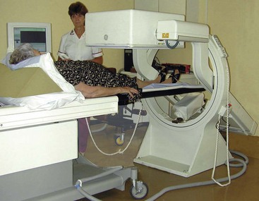
A gamma camera consisting of multiple detector units collects and counts the level of radioactivity across the area of interest. This produces a complete image in one exposure (see Fig. 5.12). Several views are taken from different directions (usually anterior, posterior and oblique).
Applications of radionuclide scanning
Lung scanning: Lung scanning was widely used in the diagnosis of pulmonary embolism but is used much less since multislice CT became widely available.
Bone scanning: Phosphate-based agents (phosphates or bisphosphonates) labelled with technetium are usually employed. The tracer is taken up in areas of increased bone deposition and resorption, indicating sites of bone growth and repair (see Fig. 5.13). These include growth plates, some primary tumours, secondary tumours, foci of bone infection, healing fracture sites, active arthritis and Paget’s disease. Bone scanning is highly sensitive but interpretation of the scans requires caution because it lacks specificity. They are usually interpreted alongside plain radiographs to improve specificity.
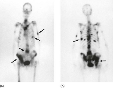
Fig. 5.13 Isotope bone scans
(a) Anterior view of bone scan in a patient with multiple bony metastases (arrowed) from breast cancer. (b) Posterior view of bone scan in the same patient
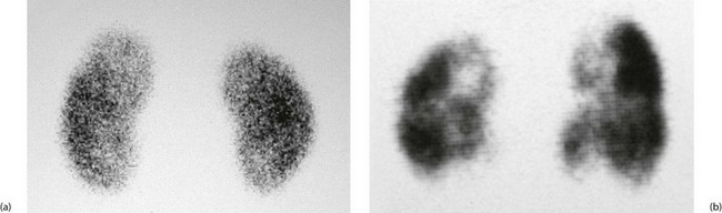
Renal scans: Renal scanning is an important method of investigating the urinary tract. It can obtain information not available from any other source, is quick and simple to perform and allows the function of each kidney to be assessed individually.
There are three main varieties of scan, using different isotopes. DTPA (diethylene tetramine penta-acetic acid) is excreted in the urine like urographic contrast, while DMSA (dimercapto-succinic acid) and MAG3 remain in cortical tissue. (Aide-mémoire: DT ‘Pee’ A, excreted in urine; D ‘Meat’ SA, retained in cortical tissue.) Examples are shown in Figure 5.14.
Scanning for gastrointestinal bleeding: Scanning using the patient’s own isotopically labelled red cells may be employed to locate a source of continuing or intermittent gastrointestinal bleeding. This is useful where the rate of bleeding is relatively slow or in a patient with recurrent haemorrhage, particularly where a source cannot be identified by endoscopy or arteriography.
Leucocyte scanning for inflammation and infection: When an abscess or other infected focus is suspected but cannot be localised, the patient’s white blood cells can be labelled with indium-111 or technetium-99m, then reinjected and scanned. Typical indications are patients with a high swinging pyrexia after operation, or with sepsis of unknown origin. The process is expensive but has a high degree of specificity and sensitivity; however, there is a small proportion of false negatives where an occult abscess is not revealed by the scan.
Thyroid scans: Thyroid scanning is described in Chapter 49. Its use is declining in favour of fine-needle aspiration and cytology except in specific disorders of thyroid function.
Cardiovascular imaging: A multiple gated acquisition (MUGA) scan can provide information about ventricular function. This can be useful following myocardial infarction or for patients receiving doxorubicin (Adriamycin) chemotherapy which can damage heart muscle. Radionuclide lymphangiography in chronic lymphoedema can demonstrate the patency and capacity of lower limb lymphatics.
Hepatobiliary imaging (HIDA scanning): Technetium-labelled imido-diacetic acid (IDA) derivatives are concentrated by hepatocytes and excreted into bile even in the presence of jaundice. This provides a means of testing the patency of the biliary tree and cystic duct.
Hepatobiliary imaging can be used for:
• Demonstrating cystic duct obstruction in suspected acute cholecystitis
• Demonstrating whether bile ducts are obstructed in jaundiced patients. This is often employed in neonates with jaundice. If there is unequivocal evidence of intestinal excretion of the radiolabel, the patency of the extrahepatic biliary system is confirmed
Flexible Endoscopy
Principles of flexible endoscopy
Fibreoptic illumination: Rigid endoscopes and early flexible instruments were illuminated by tiny incandescent bulbs prone to failure. These were superseded by fibreoptic light guides in both rigid and flexible endoscopes. Fibreoptic light guides channel light from a powerful, remote fan-cooled light source to the distal end of an endoscope. They are made up of thousands of glass fibres, each with total internal reflection, so very little light is lost and no heat is transmitted. A powerful, cool light beam emerges from the distal end of even the longest endoscope.
Image transmission: The next development crucial to the design of early flexible endoscopes was the invention of coherent viewing bundles where the orientation of fibres at the distal end exactly matched the proximal viewing end. Each fibre transmitted a tiny part of the distal scene to the viewing end. The distal end of most endoscopes allowed a viewing angle of over 100°, and lenses gave a remarkable depth of focus. Accurate diagnosis could often be made on inspection alone.
Structure of flexible endoscopes: Most flexible endoscopes include a mechanism to steer the distal end in four directions (except for specialised ultra-slender scopes), a distal imaging chip for video endoscopy, one or two fibreoptic light guides, a suction channel and a channel for inflating the hollow viscus under inspection with air, doubling as a lens washing channel (see Fig. 5.15). The suction channel is also used to pass slender flexible operating tools such as tiny forceps for biopsies, grasping forceps for retrieving foreign bodies, laser guides for therapy (haemostasis or tumour destruction), snares for excision of polyps, diathermy wires, scissors for cutting sutures and needles for injecting haemostatic agents.
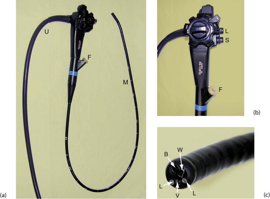
Fig. 5.15 Flexible fibreoptic gastroscope
(a) This end-viewing gastroscope is composed of a flexible main shaft M which is 1 m long and marked at 10 cm intervals; the distal 10 cm can be flexed in four directions to steer the instrument in order to advance it and to obtain the best view. There is also an ‘umbilical cord’ U which is plugged into the control box. This carries air to inflate the viscus, water to wash the viewing lens and suction to aspirate fluid from the lumen. There is a flush tube F, through which fluid can be injected to wash the stomach wall. The steering controls are better seen in (b). (b) The steering controls consist of two concentric wheels labelled respectively D and U (down and up) and L and R (left and right). The channel F is also used to pass instruments; buttons control suction S and air inflation and lens washing L. (c) shows the tip of the instrument in detail. The two light guides are marked L, V is the lens for the imaging chip, W is the exit for the inflation air and lens washing water and B is the channel for passing instruments and for suction. Note that the video image is transmitted up the ‘scope and along the umbilical cord to the processor unit, from where it is displayed on a video monitor
Applications of flexible endoscopy
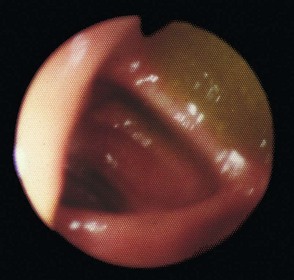
Diagnostic upper gastrointestinal endoscopy: Oesophago-gastro-duodenoscopy, also known as OGD or gastroscopy, involves inspecting the upper GI mucosa using a steerable, flexible endoscope. It is usually carried out under intravenous sedation and local anaesthetic spray on a day-case basis. Among other applications, gastroscopy enables the whole area prone to peptic ulcer disease and cancer to be directly and comprehensively examined.
Flexible endoscopy has the following advantages over GI contrast radiology:
• Structural abnormalities such as chronic ulcers can be inspected directly whereas radiology provides only a two-dimensional image with little information about surface characteristics
• Benign ulcers and early malignancies are often indistinguishable on radiology whereas at endoscopy, suspicious lesions such as ulcers can be inspected and biopsied
• Shallow mucosal abnormalities invisible on radiology such as superficial ulceration or vascular malformations can be inspected at endoscopy
• Bile reflux through the pylorus may be visible
• Fibrosis and anatomical distortions from previous disease or surgery interfere much less with recognition of what is abnormal on endoscopy than on radiology
• Endoscopy can often identify the exact site of the lesion causing acute upper gastrointestinal haemorrhage and give an indication of the rate of haemorrhage and the likelihood of rebleeding. Tracing the source is often impossible radiologically
• During endoscopy, therapy may be applied during the same procedure, e.g. injection of the source of acute bleeding, retrieving swallowed foreign body, placement of feeding gastrostomy tube
Therapeutic upper gastrointestinal endoscopy:
Treatment of upper gastrointestinal haemorrhage: First-line therapy for upper gastrointestinal haemorrhage caused by bleeding ulcers typically involves injection of the ulcer base with adrenaline solution alone or in combination with sclerosants. Other treatments such as laser or direct heat coagulation have proved less effective, but are sometimes used. With these techniques, the need for urgent surgery for bleeding has been substantially reduced. Patients successfully treated for acute haemorrhage from benign lesions can often be managed in the long term without surgery; this subject is discussed in detail in Chapter 19. Haemorrhage due to oesophageal varices is now best treated in most cases by endoscopic band ligation or injection sclerotherapy rather than surgery.
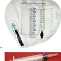
Treatment of oesophageal strictures: Endoscopic methods are often used for dilating benign strictures. The endoscope is passed until the stricture is visible and then a flexible wire is passed through into the stomach. The endoscope is removed, leaving the wire in situ. Plastic or metal dilators of increasing size are then passed over the wire which guides them safely through the stricture until sufficient dilatation is achieved. The technique is relatively safe, can easily be repeated and avoids the need for general anaesthesia. There is a small risk of oesophageal perforation (see Fig. 5.16).
Case History
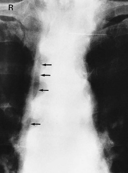
Fig. 5.16 Pneumomediastinum following perforation of an oesophageal tumour during endoscopy
This 56-year-old man who was being investigated for difficulty in swallowing complained of chest pain after the examination. Crepitus was found in the neck due to surgical emphysema resulting from oesophageal air leaking out of the perforation and tracking up the mediastinum into the neck
Diagnostic and therapeutic duodenoscopy: A side-viewing duodenoscope can be used to inspect the duodenal papilla and guide insertion of a cannula or therapeutic tools. Cannulation allows injection of contrast material into the common bile duct and separately into the pancreatic duct. The technique is known as ERCP (endoscopic retrograde cholangio-pancreatography) (see Fig. 5.17 and Ch. 11) and is an important part of gastroenterological investigation.
Case History
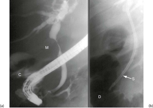
Fig. 5.17 Stenting of biliary stricture
(a) This 54-year-old man developed painless, unremitting obstructive jaundice. This ERCP shows a malignant stricture of the common bile duct M due to cholangiocarcinoma. Contrast has been injected to outline the bile ducts and has leaked back into the duodenum C. (b) A stent S was placed endoscopically across the stricture for palliation. The second part of the duodenum is outlined by gas D
Enteroscopy: Barium follow-through, CT and MRI have low rates of positive diagnosis in small bowel disorders. Direct small bowel visualisation used to be achieved by ‘push’ enteroscopy (with a 2 m endoscope that could examine up to a metre beyond the duodeno-jejunal flexure) or by operative enteroscopy via a laparotomy. Later, a technique of double-balloon enteroscopy appeared, with an endoscope passed via the mouth and then coaxed along the small bowel using attached balloons as counter-traction. None of these methods was convenient or reliable.
Large bowel endoscopy (colonoscopy): Flexible endoscopes of different lengths are available for large bowel examination (see Fig. 5.18). The shortest, the fibreoptic sigmoidoscope, is about 60 cm long. It is simple to use and allows examination of the rectum, sigmoid colon and descending colon with minimal bowel preparation. Longer colonoscopes enable the entire large bowel to be inspected, and vary in stiffness to assist intubation to the caecum. Other techniques also help reach the caecum, including insufflation with carbon dioxide rather than air, and releasing seed oil from the tip to lubricate the instrument.