Image processing
Chemical processing
It is CRUCIAL that the stages involved in chemical processing are performed under controlled, standardized conditions with careful attention to detail. Strict quality assurance procedures must be applied (see Ch. 17). Unfortunately, all too often in dental practice poor chemical processing is the cause of radiographic films being of inadequate diagnostic quality, irrespective of how reliable and expensive the X-ray equipment or how accurate the operator’s radiographic techniques.
Theory
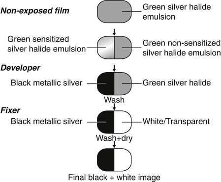
A detailed knowledge of the chemistry involved in processing is not essential. However, a working knowledge and understanding of the theory of processing is necessary so that processing faults can be identified and corrected. A simplified approach to the stages involved in converting the green film emulsion into the black/white/grey radiograph is shown in Fig. 5.1 and outlined below:
Practical methods
There are three practical chemical processing methods available:
Manual processing
• Adequate film storage facilities
• Safelights – positioned 1.2 m from the work surfaces with 25 W bulbs and filters suitable for the type of film being used (see Ch. 17)
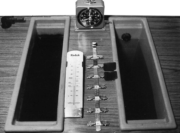
Manual processing cycle
1. The exposed film packet is unwrapped and the film clipped on to a hanger.
2. The film is immersed in developer and agitated several times in the solution to remove air bubbles and left for about five minutes at 20 °C.
3. The residual developer is rinsed off in water for about 10 seconds.
4. The film is immersed in fixer for about 8–10 minutes.
5. The film is washed in running water for about 10–20 minutes to remove any residual fixer.
Processing solutions
Two different processing solutions are required, the developer and the fixer. The typical constituents of these solutions are shown in Tables 5.1 and 5.2.
Table 5.1
The typical constituents of developer solution and their functions
| Constituents | Functions |
| Phenidone | Helps bring out the image |
| Hydroquinone | Builds contrast |
| Sodium sulphite | Preservative – reduces oxidation |
| Potassium carbonate | Activator – governs the activity of the developing agents |
| Benzotriazole | Restrainer – prevents fog and controls the activity of the developing agents |
| Glutaraldehyde | Hardens the emulsion |
| Fungicide | Prevents fungal growth |
| Buffer | Maintains pH (7+) |
| Water | Solvent |
Table 5.2
The typical constituents of fixer solution and their functions
| Constituents | Functions |
| Ammonium thiosulphate | Removes unsensitized silver halide crystals |
| Sodium sulphite | Preservative – prevents deterioration of the fixing agent |
| Aluminium chloride | Hardener |
| Acetic acid | Acidifier – maintains pH |
| Water | Solvent |
Important points to note regarding development
• The alkaline developer solution should be made up to the concentration recommended in the manufacturer’s instructions.
• The developer solution is oxidized by air and its effectiveness decreased. Solutions should be used for no more than 10–14 days, irrespective of the number of films processed during that time.
• If the development process is allowed to continue for too long, more silver will be deposited than was intended and the radiograph will be too dark. Conversely, if there is too short a development time the radiograph will be too light.
• Development time (in fresh solutions) is dependent on the temperature of the solution. The usual value recommended is five minutes at 20°C.
• If the temperature is too high, development is rapid, the film may be too dark and the emulsion may be damaged. If the temperature is too low, development is slowed and a pale film will result.
Important points to note regarding fixing
• Fixer solution should be made up to the concentration recommended by the manufacturer. It is an acid solution so contamination with developer should be avoided.
• Ideally films should be fixed for double the clearing time. The clearing time is how long it takes to remove the unsensitized silver halide crystals. Total fixing time is usually 8–10 minutes.
• Films may be removed from the fixer after 2–4 minutes for wet viewing but should be returned to the fixer solution to complete fixing.
• Inadequately fixed films may appear greenish yellow or milky owing to residual emulsion. In time these films may discolour further, becoming brown.
Automatic processing
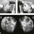
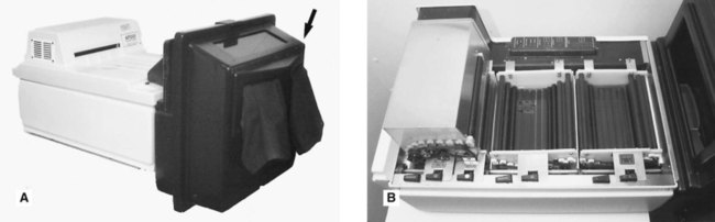
This term is used when processing is carried out automatically by a machine. There are several automatic processors available which are designed to carry the film through the complete cycle usually by a system of rollers. Most have a daylight loading facility, eliminating the need for a dark-room (see Fig. 5.3), but in the interests of infection control, salivary-contaminated film packets should be wiped with a disinfecting solution such as 1% hypochlorite, before being placed into the loading facility.
Self-developing films
Self-developing films are an alternative to manual processing. The X-ray film is presented in a special sachet containing developer and fixer (see Fig. 5.4). Following exposure, the developer tab is pulled, releasing developer solution which is milked down towards the film and massaged around it. After about 15 seconds, the fixer tab is pulled to release the fixer solution which is similarly milked down to the film. After fixing, the used chemicals are discarded and the film is rinsed thoroughly under running water for about 10 minutes.
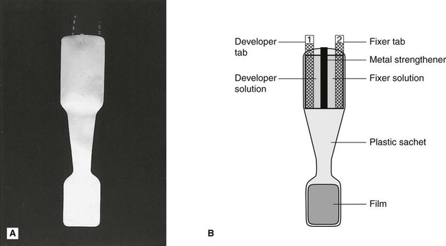
Disadvantages
The main disadvantages include:
• The image deteriorates rapidly with time
• There is no lead foil inside the film packet
• The film packet is very flexible and easily bent
A rigid, radiopaque plastic backing support tray for the film is manufactured, which helps to reduce the problems of flexibility and lack of lead foil.
Computer digital processing
Digital image
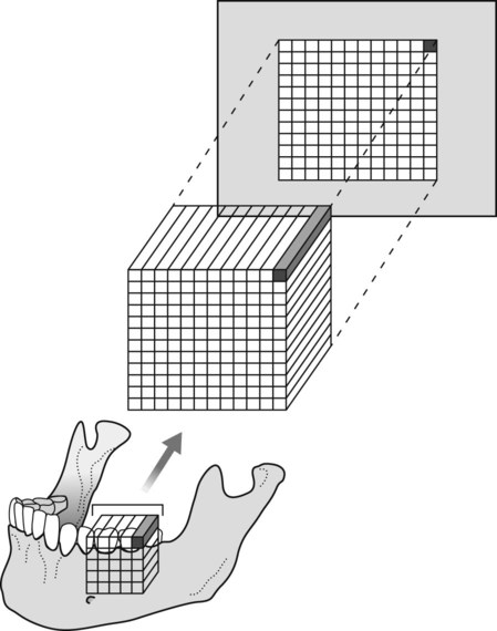
The digital image is captured in pixels (tiny squares), by two different types of sensor – solid-state or photostimulable phosphor plates described in Chapter 4. However captured, the digital image is similar to a film-captured image, in that both are 2-dimensional representations of a 3-dimensional object. In digital imaging, each 2-D pixel represents a 3-D cuboid or voxel of the patient. This is shown diagrammatically in Fig. 5.5. The depth of the cuboid is dependent on the thickness of the part of the body being X-rayed. Each pixel measures the total X-ray absorption throughout the whole of each voxel. This 2-D limitation has been overcome with the development of cone beam computed tomography (CBCT) (see Ch. 16).
Computer input
Phosphor plates
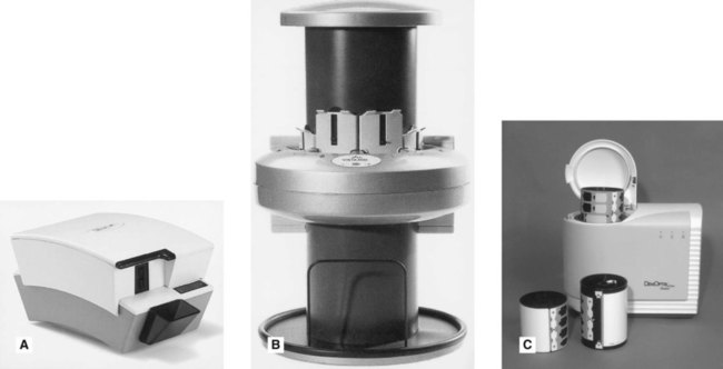
Phosphor plates are not directly connected to the computer and therefore an intermediary stage is required when the plate is read. The time taken to read the plate depends on the particular system being used, and the size of the plate, but typically varies between 5–100 seconds. Several dental systems are available including Soredex’s Digora® Optime (intraoral) and PCT (extraoral), Durr’s Vistascan and the Gendex® DenOptix™ (see Fig. 5.6). Although different in design they all work on the same principle, namely:
• During the radiographic procedure the phosphor layer on the plate absorbs and stores the X-ray energy that has not been attenuated by the patient.
• The plate is then placed in the reader.
• The plate is scanned by a laser beam and the stored X-ray energy is released as light.
• The light is detected by a photomultiplier tube and converted into an electrical signal (voltage) and input to the connected computer’s analogue-to-digital converter.
Computer processing theory
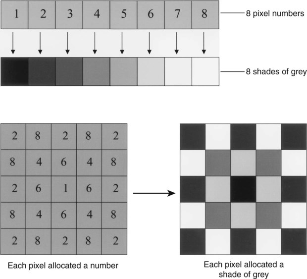
Computers deals with numbers, hence the need for the analogue voltage from each pixel to be changed by the analogue-to-digital converter into a discrete numerical digital signal. Each pixel has an x and y coordinate and is allocated a number. Typically using the grey-scale there are 256 numbers to select. These range from 0, when the voltage received is at its maximum (no X-ray attenuation in the patient), to 255 when there is no voltage (total X-ray attenuation in the patient). The computer finally allocates an appropriate colour from the grey scale (256 shades of grey from black through to white) to each pixel (0 = black, 255 = white) to create the visual image on the monitor. This concept is illustrated simply in Fig. 5.7 using just eight numbers and eight shades of grey.
The number and size of the pixels, together with the number of shades of grey available, determine the amount of information in an image, the size of the image file and the resolution of the final image (see Fig. 5.8). Pixel sizes vary from 20 µm to 70 µm, producing resolution between 7 and 25 line pairs/mm.
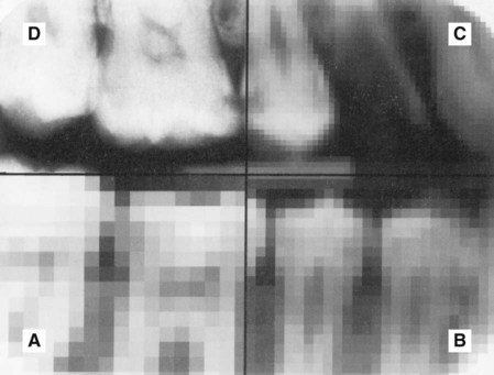
Image manipulation
Digital images can be changed by giving the pixels different numbers so altering the shades of grey. Different colours can be used. The coordinates of pixels may be changed or swapped, allowing different parts of the image to be moved around. These variables are the basis for image manipulation and enhancement. Software packages allow several enhancement techniques, some of which are shown in Fig. 5.9. These can include:
The two most frequently used enhancement functions are altering brightness and contrast.
Brightness
Brightness can be regarded as equivalent to the degree of blackening of a film-captured image. Increasing brightness decreases the degree of blackening and makes the image lighter. This is done by increasing the numerical value of each pixel in the image and allocating it a lighter shade of grey. Taken to the extreme, every pixel would be allocated the highest number and the image will be totally white. The concept of altering brightness is illustrated in Fig. 5.10, using the same simple model of eight numbers and eight shades of grey. Conversely, decreasing brightness increases the degree of blackening and makes the image darker.
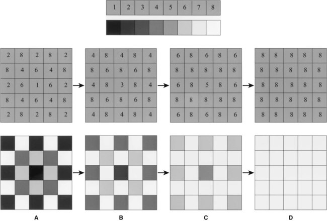
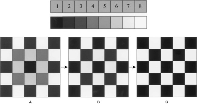
Contrast
Contrast is the visual difference between black and white. Increasing contrast increases this difference. This is done by decreasing the pixel numbers in the darker half of the grey-scale and increasing the pixel numbers in the lighter half. Taken to the extreme, every pixel would be allocated either the lowest number available or the highest and the image would be black and white only containing no shades of grey. The concept of altering contrast is illustrated in Fig. 5.11 using the same simple model of eight shades of grey. Conversely, decreasing contrast results in a grey image with little visual difference between the pixels.
Hard copy printed images
Advantages
• No need for chemical processing, thus avoiding all conventional processing faults (see Ch. 17) and the hazards associated with handling chemical solutions.
• Easy storage and archiving of patient information and incorporation into patient records.
• Easy transfer of images electronically.
• Image enhancement and manipulation.
• Phosphor plates have a wide latitude producing an acceptable image whether underexposed or overexposed.
Disadvantages
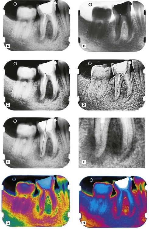
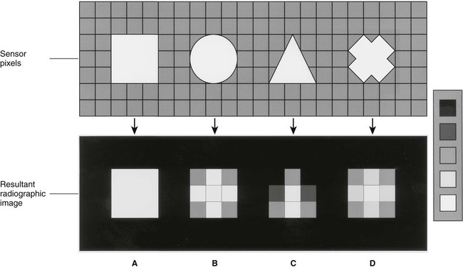
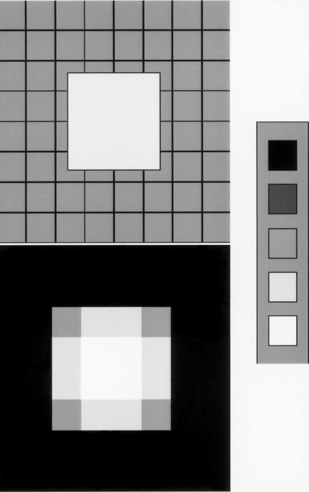
• Large pixels result in poor resolution and structures may not be represented accurately, as shown in Figs 5.12 and 5.13.
• Conventional PC screens/monitors reduce or limit image quality. Diagnostic image quality screens/monitors are required for optimal viewing.
• Images need to be backed up to a separate storage area remote from the image-capture computer in case this computer fails.
• Over-exposure and overloading of CCD sensors creating the phenomenon of blooming (see Ch. 17).
• Loss of image quality and resolution on hard copy print-outs when using thermal, laser or ink-jet printers.
• Image enhancement and manipulation:
– operators need to understand how the image is created and being altered to avoid being misled
– magnification is achieved by enlarging the pixels, but resolution is lost.
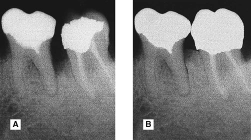
• While manufacturers provide safeguards to prevent any tampering with original images within their own software, it is relatively easy to access these images using inexpensive third party software and then to change them, as shown in Fig. 5.14.
 and
and  , the lack of contact point and the restoration in
  . B After digital manipulation and no clinical treatment.
To access the self assessment questions for this chapter please go to www.whaitesessentialsdentalradiography.com