CHAPTER 305 Image-Guided Spinal Navigation
Principles and Clinical Applications
Image-guided spinal navigation is a computer-based surgical technology designed to improve intraoperative orientation to the unexposed anatomy during complex spinal procedures.1,2 It evolved from the principles of stereotaxy, which have been used by neurosurgeons for several decades to help localize intracranial lesions. Stereotaxy is defined as the localization of a specific point in space using three-dimensional coordinates. The application of stereotaxy to intracranial surgery initially involved the use of an external frame attached to the patient’s head. However, the evolution of computer-based technologies has eliminated the need for this frame and has allowed for the expansion of stereotactic technology into other surgical fields, in particular, spinal surgery.
Several studies have shown the unreliability of routine radiography in assessing pedicle screw placement in the lumbosacral spine. The rate of disruption of the pedicle cortex by an inserted screw ranges from 21% to 31% in these studies.3–5 The disadvantage of these conventional radiographic techniques in orienting the spinal surgeon to the unexposed spinal anatomy is that they display, at most, only two planar images. Although the lateral view can be relatively easy to assess, the anteroposterior or oblique view can be difficult to interpret. For most screw fixation procedures, it is the position of the screw in the axial plane that is most important. This plane best demonstrates the position of the screw relative to the neural canal. Conventional intraoperative imaging cannot provide this view.
To assess the potential advantage of axial imaging for screw placement, Steinmann and associates used an image-based technique for pedicle screw placement that combined computed tomography (CT) axial images of cadaver spine specimens with fluoroscopy. This study demonstrated an improvement in pedicle screw insertion accuracy with an error rate of only 5.5%.6
Principles Of Image-Guided Spinal Navigation
The use of an image-guided navigational system for localizing intracranial lesions has been previously described.7,8 Image-guided navigation establishes a spatial relationship between a preoperative CT image and its corresponding intraoperative anatomy. Both the CT image and the anatomy can each be viewed as a three-dimensional coordinate system with each point in that system having a specific x, y, and z Cartesian coordinate. Using defined mathematical algorithms, a specific point in the image data set can be matched to its corresponding point in the surgical field. This process is called registration and represents the critical step of image-guided navigation. At least three points need to be matched, or registered, to allow for accurate navigation.
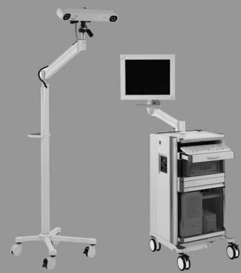
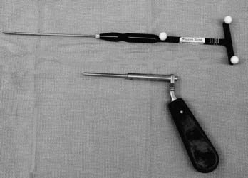
A variety of navigational systems have evolved during the past decade. The common components of most of these systems include an image-processing computer workstation interfaced with a two-camera optical localizer (Fig. 305-1). When positioned during surgery, the optical localizer emits infrared light toward the operative field. A handheld navigational probe mounted with a fixed array of passive reflective spheres serves as the link between the surgeon and the computer workstation (Fig. 305-2). Alternatively, passive reflectors may be attached to standard surgical instruments. The spacing and positioning of the passive reflectors on each navigational probe or customized trackable surgical instrument is known by the computer work-station. The infrared light that is transmitted toward the operative field is reflected back to the optical localizer by the passive reflectors. This information is then relayed to the computer work-station, which can then calculate the precise location of the instrument tip in the surgical field as well as the location of the anatomic point on which the instrument tip is resting.
The initial application of navigational principles to spinal surgery was not intuitive. Early navigational technology applied to intracranial surgery used an external frame mounted to the patient’s head to provide a point of reference to link preoperative image data to intracranial anatomy. This was not practical for spinal surgery. The current generation of intracranial navigational technology uses reference markers or fiducials that are attached to the patient’s scalp before imaging. However, the use of these surface-mounted fiducials for spinal navigation is not practical because of accuracy issues related to a greater degree of skin movement over the spinal column.9,10 This is less of a problem with intracranial applications because of the relatively fixed position of the overlying scalp to the underlying anatomy.
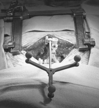
The application of navigational technology to spinal surgery involves using the rigid spinal anatomy as a frame of reference. Bone landmarks on the exposed surface of the spinal column provide the points of reference necessary for image-guided navigation. Specifically, any anatomic landmark that can be identified intraoperatively as well as in the preoperative image data set can be used as a reference point. The tip of a spinous or transverse process, a facet joint, or a prominent osteophyte can serve as a potential reference point (Fig. 305-3). Because each vertebra is a fixed, rigid body, the spatial relationship of the selected registration points to the vertebral anatomy at a single spinal level and is not affected by changes in body position.
The purpose of the registration process is to establish a precise spatial relationship of the image data with the physical space of the patient’s corresponding surgical anatomy. If the patient is moved after registration, this spatial relationship is distorted, making the navigational information inaccurate. This problem can be minimized by the optional use of a spinal tracking device consisting of a separate set of four passive reflectors mounted in a known configuration on a small frame. This reference frame can be attached to the exposed spinal anatomy and its position in space tracked by the infrared camera system (Fig. 305-4). Movement of the spinal anatomy and the attached frame alerts the navigational system, which can then make the appropriate correctional calculations to maintain accuracy and eliminate the need to repeat the registration process. The disadvantage of using a tracking device is the added time needed for its attachment to the spine, the need to maintain a line of sight between it and the camera, and the inconvenience of having to perform the procedure with the device placed in the surgical field. It is particularly cumbersome when image-guided navigation is used during cervical procedures. Alternatively, image-guided spinal navigation can be performed without a tracking device.1,12 This involves acknowledging the effect of patient movement on the accuracy of image-guided navigation and maintaining reasonably stable patient position during the relatively short amount of time needed (i.e., 10 to 20 seconds) for the selection of each appropriate screw trajectory. Patient movement can potentially occur with respiration, from the surgical team leaning on the table, or from a change of table position. Movement associated with patient respiration is negligible and does not require any tracking, even in the thoracic spine. Although movement associated with leaning on the table or repositioning the table or the patient will affect registration accuracy, it can be easily avoided during the short navigational procedure. If inadvertent patient movement does occur, the registration process can be repeated.
Alternatively, a second registration technique called surface matching can be used. This technique involves selecting multiple, random (nondiscrete) points on the exposed surface of the spine in the surgical field. This technique does not require prior selection of points in the image set, although several discrete points in both the image data set and the surgical field are frequently required to improve the accuracy of surface mapping. The positional information of these points is transferred to the work-station, and a topographic map of the selected anatomy is created and matched to the patient’s image set.11
Typically, paired point registration can be done more quickly than surface mapping. The average time needed for paired point registration is 10 to 15 seconds. The time needed for surface mapping is much longer, with difficult cases requiring as much as 10 to 15 minutes. With the need to perform several registration processes during each surgery, this time difference can significantly affect the length of the navigational procedure and the surgery.12
Clinical Applications
Image-guided spinal navigation was initially evaluated for the insertion of pedicle screws in the thoracic and lumbosacral spines of cadaver specimens. The accuracy of screw insertion was documented by plain film radiography and thin-section CT imaging of the instrumented levels. Satisfactory screw placement was noted for 149 of 150 inserted screws.2 The initial clinical application of image-guided spinal navigation was its use for lumbosacral pedicle fixation.1,13,14 Other spinal applications gradually evolved including transoral decompression, cervical screw fixation, thoracic pedicle fixation, decompression of spinal metastasis, and anterior thoracolumbar decompression and fixation procedures.12,15–20
Pedicle Fixation
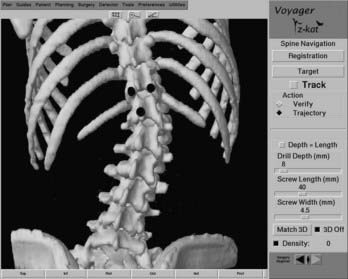
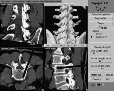
When an accurate registration of the first spinal level to be instrumented has been verified, standard bony landmarks for pedicle localization are used to approximate the screw entry point. A drill guide is placed on this entry point, and the navigation probe is passed through the guide. The navigational system is activated, permitting tracking of the probe in the surgical field. Three separate reformatted views are displayed on the work-station screen. Each view represents a separate plane passing through the selected point in the surgical field. For most pedicle fixation cases, these views typically consist of a sagittal, an axial, and a coronal reconstruction. A trajectory line referenced to the long axis of the probe is superimposed on the sagittal and axial views. A round cursor, representing a cross section through the selected trajectory, is superimposed on the coronal view. As the probe is moved through the surgical field, the position of the trajectory line and cursor will change accordingly. Both the width of the trajectory line and the diameter of the cursor can be adjusted to match the relative diameter of the pedicle screws to be used. The length of the trajectory line can also be adjusted (Fig. 305-5).
In addition to screw placement in the large pedicles of the lumbosacral spine, image-guided navigation can also facilitate screw placement into the smaller pedicles of the thoracic spine (Fig. 305-6). The added precision for screw placement into thoracic pedicles greatly expands the fixation options for managing the unstable thoracic spine and cervicothoracic junction.
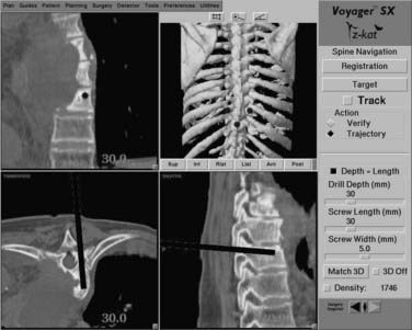
FIGURE 305-6 Workstation screen demonstrating navigation for a T8 pedicle screw in a patient with mycotic aneurysm of the aorta.
Image-guided navigation can also be used in place of fluoroscopy for placement of interbody cages in the lumbosacral spine. During removal of the intervertebral disk, the navigational probe can be inserted into the evacuated disk space. With the trajectory length set at zero, the three reformatted images displayed provide optimal spatial orientation to the disk space, allowing for precise placement of the cages (Fig. 305-7).
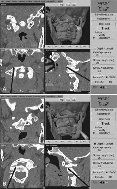
C1-2 Transarticular Screw Fixation
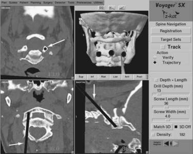
Two separate stab incisions are made on either side of the midline at the C7-T1 level. A drill guide is placed through one of the stab incisions and passed through the paravertebral musculature and into the operative field. A small divot is drilled at the proposed entry site to provide for secure placement of the drill guide. The registration process is performed at the C2 level and its accuracy confirmed using the verification step. The probe is passed through the drill guide, and as its position is adjusted in the surgical field, the images on the workstation screen will adjust accordingly to show the corresponding trajectory in two separate planes and the projected location of the screw tip in the third plane. Orientation to the correct screw position can be assessed rapidly and accurately (Fig. 305-8). Any errors in trajectory or entry point selection can be determined and corrected by adjusting the position of the probe and the drill guide through which it passes. When the correct screw insertion parameters have been selected, the probe is removed from the drill guide, and a drill is inserted. A hole is drilled along the selected trajectory, tapped, and the appropriate length screw inserted. The process is repeated on the opposite side.
Segmental C1-2 Screw Fixation
As an alternative to transarticular screw fixation, segmental fixation of C1-2 can be used for managing atlantoaxial instability.21 The procedure involves placing a screw into each of the two lateral masses of C1 and two screws down the pedicles of C2. The polyaxial screw heads on each side are then connected with rods. Although this approach potentially reduces the risk for injury to the vertebral artery during screw insertion, it does not eliminate the risk. As with the transarticular technique, precise anatomic orientation is required to avoid arterial or neural injury. Image guidance can supplement intraoperative fluoroscopy to provide the necessary orientation for accurate screw insertion.
As with the transarticular screw fixation technique, a preoperative CT scan is obtained. The posterior C1-2 spine is exposed, and a wire and cable fixation procedure is carried out. Registration is first performed at C1 for placement of the C1 lateral mass screws. The three registration points typically used at C1 include the midline posterior tubercle and the bilateral points marked by the junction of the small pedicle of C1 with its lateral mass (immediately above the two exiting C2 nerve roots). Once registered, the correct trajectory into the lateral mass can be displayed on the workstation screen and the screws inserted (Fig. 305-9). To use image guidance for inserting C2 pedicle screws, the same registration points are used at C2 as those used for transarticular fixation (the C2 spinous process and the two lateral margins of the C2-3 facet). The entry point for the screw is more lateral and the trajectory more medially oriented than for a transarticular screw. The navigation probe is placed through a drill guide onto this entry point and the selected trajectory is displayed on the workstation screen. When the correct entry point and trajectory have been selected, the probe is removed, a drill is inserted, and the pilot hole is drilled. The process is then repeated for the other side. The heads of the screws are then connected with two short rods.
Transoral Surgery
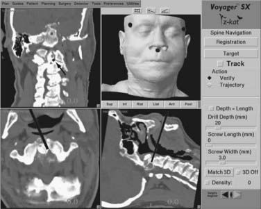
Transoral decompression of the upper cervical spine typically requires intraoperative fluoroscopy to help maintain proper anatomic orientation during the procedure. Although orientation in the sagittal plane is easy to obtain with fluoroscopy, depth and medial-lateral orientation are more difficult to assess. Image-guided technology can be used to orient the surgeon in multiple planes during transoral surgery.12,22
During the procedure, the probe can be placed into the site of the decompression. Reformatted sagittal, axial, and coronal CT images are immediately generated providing the surgeon with a precise orientation to the pertinent surgical anatomy. In particular, orientation in the axial plane minimizes the risk for lateral deviation toward the vertebral artery during the decompression (Fig. 305-10). If a posterior fixation is indicated following transoral decompression, the same CT image data set can be used for C1-2 screw placement
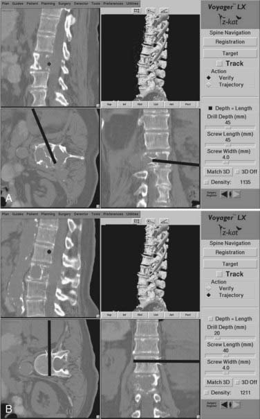
Anterior Thoracolumbar Surgery
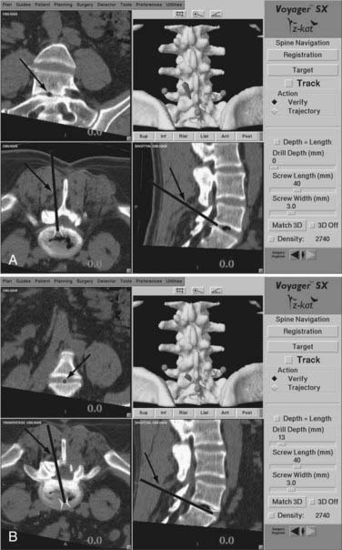
During anterior decompression, the probe can be placed into the partially decompressed site to orient the surgeon to the contralateral margin of the spinal column and, more importantly, to the location of the epidural space (Fig. 305-11A). Orientation to tumor margins can also be obtained by placing the probe into the partially decompressed tumor bed. After decompression, image guidance can be used to guide anterior fixation screws across the vertebra at either end of the corpectomy site (Fig. 305-11B).
Fluoroscopic Navigation
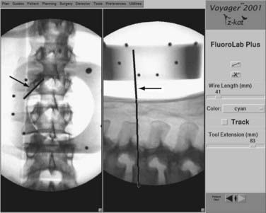
Fluoroscopic navigation is the combination of standard fluoroscopy with image-guided navigational technology. It was developed to address the difficulties of some earlier image-guided systems that typically took much longer to use than standard fluoroscopy.22 Although standard fluoroscopy is employed with this technique, the amount of fluoroscopic time is significantly reduced.
With the patient in position before surgery, an anteroposterior and lateral fluoroscopic view of the pertinent spinal anatomy is obtained. This is done with a customized reference frame attached to the C arm. The frame serves to superimpose a specific reference grid on the two images obtained. The navigational work station can then take the two images with the superimposed grid and relate the spatial position of the imaged anatomy to a navigational probe. As the navigational probe is place on the patient’s anatomy, a corresponding trajectory line and cursor can then be superimposed on the lateral and anteroposterior images, respectively (Fig. 305-e12).
Assaker R, Reyns N, Vinchon M, et al. Transpedicular screw placement. Image-guided versus lateral-view fluoroscopy: In vitro simulation. Spine. 2001;26:2160-2164.
Barnett GH, Kormos DW, Steiner CP, Weisenberger J. Intraoperative localization using an armless, frameless stereotactic wand. Technical note. J Neurosurg. 1993;78:510-514.
Barnett GH, Kormos DW, Steiner CP, Weisenberger J. Use of a frameless, armless stereotactic wand for brain tumor localization with two-dimensional and three-dimensional neuroimaging. Neurosurgery. 1993;33:674-678.
Brodwater BK, Roberts DW, Nakajima T, et al. Extracranial application of the frameless stereotactic operating microscope: Experience with lumbar spine. Neurosurgery. 1993;32:209-213.
Bryant JT, Reid JG, Smith BL, Stevenson JM. A method for determining vertebral body positions in the sagittal plane using skin markers. Spine. 1989;14:258-265.
Foley KT, Simon DA, Rampersaud YR. Virtual fluoroscopy: computer-assisted fluoroscopic navigation. Spine. 2001;26:347-351.
Foley KT, Smith MM. Image-guided spine surgery. Neurosurg Clin N Am. 1996;7:171-186.
George DC, Krag MH, Johnson CC, et al. Hole preparation technique for transpedicle screws: effect on pull-out strength from human cadaveric vertebrae. Spine. 1991;16:181-184.
Gertzbein SD, Robbins SE. Accuracy of pedicle screw placement in vivo. Spine. 1990;15:11-14.
Glossop ND, Hu RW, Randle JA. Computer-aided pedicle screw placement using frameless stereotaxis. Spine. 1996;21:2026-2034.
Harms J, Melcher R. Posterior C1-C2 fusion with polyaxial screw and rod fixation. Spine. 2001;26:2467-2471.
Kalfas IH. Image-guided spinal navigation: application to spinal metastasis. In: Maciunas RJ, editor. Advanced Techniques in Central Nervous System Metastasis. Lebanon, NH: AANS Publications; 1998:245-254.
Kalfas IH. Image-guided spinal navigation. Clin Neurosurg. 1999;46:70-88.
Kalfas IH. Frameless stereotaxy assisted spinal surgery. In: Renganchary SS, editor. Neurosurgery Operative Color Atlas. Lebanon, NH: AANS Publications; 2000:123-134.
Kalfas IH, Kormos DW, Murphy MA, et al. Application of frameless stereotaxy to pedicle screw fixation of the spine. J Neurosurg. 1995;83:641-647.
Laine T, Lund T, Ylikoski M, et al. Accuracy of pedicle screw insertion with and without computer assistance: a randomised controlled clinical study in 100 consecutive patients. Eur Spine J. 2000;9:235-240.
Murphy MA, McKenzie RL, Kormos DW, Kalfas IH. Frameless stereotaxis for the insertion of lumbar pedicle screws: a technical note. J Clin Neurosci. 1994;1:257-260.
Pellizzari CA, Levin DN, Chen GTY, Chen CT. Image registration based on anatomic surface matching. In: Maciunas RJ, editor. Interactive Image-Guided Neurosurgery. Park Ridge, IL: American Association of Neurological Surgeons; 1993:47-62.
Steinmann JC, Herkowitz HO, El-Kommos H, Wesolowski DP. Spinal pedicle fixation: confirmation of an image-based technique for screw placement. Spine. 1993;18:1856-1861.
Weinstein JN, Spratt KF, Spengler D, et al. Spinal pedicle fixation: reliability and validity of roentgenogram-based assessment and surgical factors on successful screw placement. Spine. 1988;13:1012-1018.
Welch WC, Subach BR, Pollack IF, Jacobs GB. Frameless stereotactic guidance for surgery of the upper cervical spine. Neurosurgery. 1997;40:958-964.
Youkilis AS, Quint DJ, McGillicuddy JE, Papadopoulos SM. Stereotactic navigation for placement of pedicle screws in the thoracic spine. Neurosurgery. 2001;48:771-778.
1 Kalfas IH, Kormos DW, Murphy MA, et al. Application of frameless stereotaxy to pedicle screw fixation of the spine. J Neurosurg. 1995;83:641-647.
2 Murphy MA, McKenzie RL, Kormos DW, Kalfas IH. Frameless stereotaxis for the insertion of lumbar pedicle screws: a technical note. J Clin Neurosci. 1994;1:257-260.
3 George DC, Krag MH, Johnson CC, et al. Hole preparation technique for transpedicle screws: effect on pull-out strength from human cadaveric vertebrae. Spine. 1991;16:181-184.
4 Gertzbein SD, Robbins SE. Accuracy of pedicle screw placement in vivo. Spine. 1990;15:11-14.
5 Weinstein JN, Spratt KF, Spengler D, et al. Spinal pedicle fixation: Reliability and validity of roentgenogram-based assessment and surgical factors on successful screw placement. Spine. 1988;13:1012-1018.
6 Steinmann JC, Herkowitz HO, El-Kommos H, Wesolowski DP. Spinal pedicle fixation: confirmation of an image-based technique for screw placement. Spine. 1993;18:1856-1861.
7 Barnett GH, Kormos DW, Steiner CP, Weisenberger J. Use of a frameless, armless stereotactic wand for brain tumor localization with two-dimensional and three-dimensional neuroimaging. Neurosurgery. 1993;33:674-678.
8 Barnett GH, Kormos DW, Steiner CP, Weisenberger J. Intraoperative localization using an armless, frameless stereotactic wand. Technical note. J Neurosurg. 1993;78:510-514.
9 Brodwater BK, Roberts DW, Nakajima T, et al. Extracranial application of the frameless stereotactic operating microscope: experience with lumbar spine. Neurosurgery. 1993;32:209-213.
10 Bryant JT, Reid JG, Smith BL, Stevenson JM. A method for determining vertebral body positions in the sagittal plane using skin markers. Spine. 1989;14:258-265.
11 Pellizzari CA, Levin DN, Chen GTY, Chen CT. Image registration based on anatomic surface matching. In: Maciunas RJ, editor. Interactive Image-Guided Neurosurgery. Park Ridge, IL.: American Association of Neurological Surgeons; 1993:47-62.
12 Kalfas IH. Image-guided spinal navigation. Clin Neurosurg. 1999;46:70-88.
13 Foley KT, Smith MM. Image-guided spine surgery. Neurosurg Clin N Am. 1996;7:171-186.
14 Glossop ND, Hu RW, Randle JA. Computer-aided pedicle screw placement using frameless stereotaxis. Spine. 1996;21:2026-2034.
15 Assaker R, Reyns N, Vinchon M, et al. Transpedicular screw placement. Image-guided versus lateral-view fluoroscopy: in vitro simulation. Spine. 2001;26:2160-2164.
16 Kalfas IH. Image-guided spinal navigation: application to spinal metastasis. In: Maciunas RJ, editor. Advanced Techniques in Central Nervous System Metastasis. Lebanon, NH: AANS Publications; 1998:245-254.
17 Kalfas IH. Frameless stereotaxy assisted spinal surgery. In: Renganchary SS, editor. Neurosurgery Operative Color Atlas. Lebanon, NH: AANS Publications; 2000:123-134.
18 Laine T, Lund T, Ylikoski M, et al. Accuracy of pedicle screw insertion with and without computer assistance: a randomised controlled clinical study in 100 consecutive patients. Eur Spine J. 2000;9:235-240.
19 Welch WC, Subach BR, Pollack IF, Jacobs GB. Frameless stereotactic guidance for surgery of the upper cervical spine. Neurosurgery. 1997;40:958-964.
20 Youkilis AS, Quint DJ, McGillicuddy JE, Papadopoulos SM. Stereotactic navigation for placement of pedicle screws in the thoracic spine. Neurosurgery. 2001;48:771-778.
21 Harms J, Melcher R. Posterior C1-C2 fusion with polyaxial screw and rod fixation. Spine. 2001;26:2467-2471.
22 Welch WC, Subach BR, Pollack IF, Jacobs GB. Frameless stereotactic guidance for surgery of the upper cervical spine. Neurosurgery. 1997;40:958-964.
23 Foley KT, Simon DA, Rampersaud YR. Virtual fluoroscopy: computer-assisted fluoroscopic navigation. Spine. 2001;26:347-351.