CHAPTER 26 IDET Technique
INTRODUCTION
Intradiscal electrothermal therapy (IDET) is a recently proposed and investigated treatment for intractable discogenic pain. There is good evidence that IDET denatures collagen and causes changes in disc protein.1 Yet, these changes do not alter the fundamental biomechanics of the intact motion segment.2 Relatively speaking, it is a minimally invasive technique when compared to fusion or total disc arthroplasty. An important attribute of this treatment is that it does not preclude the future application of these more invasive treatments while the corollary is not true. Once disc replacement or fusion is undertaken, IDET is no longer a viable treatment option at that disc level.
RELEVANT ANATOMY AND THE IDET PROCEDURE
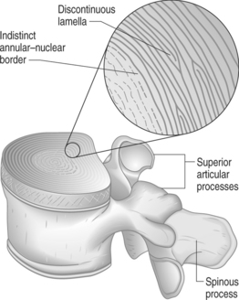
Secondly, each lamella consists of obliquely oriented parallel collagen fibers. The direction of this obliquity is rotated 90° in adjacent lamellae so that the fibers between any two adjacent lamellae form a rough ‘X’ shape. This configuration contributes to the integrity of the anulus under similar forces. While the majority of lamellae form complete rings around the circumference of the disc, as many as 50% of the lamellae at the posterolateral corners are incomplete.3 Where a lamella ends, the superficial and deep rings approximate or fuse together (Fig. 26.1). Advancement of the blunt catheter tip past these fusion points may account for some of the difficulty of passing around the posterolateral corner. The tip, which tracks easily between lamellae when traveling within the anulus, may be unable to penetrate the fused lamellae at the terminus of the layer it is following.
Covering the entire nucleus and a portion of the annular ring is a layer of hyaline and fibrocartilage known as the vertebral endplate. It is bordered by the slightly raised perimeter of the vertebral body called the ring apophysis. The endplate is securely attached to the disc with the fibers of the inner lamellae being continuous with the fibrocartilage of the endplate.
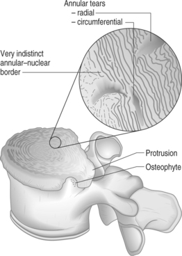
With aging, the water content of the disc diminishes and the disc becomes more fibrous. Collagen content of both the nucleus and anulus increases4 and the disc becomes increasingly less pliant as a result. The inner anulus expands at the expense of the nucleus and the boundary between them becomes less distinct. With dehydration the nucleus becomes less able to transmit forces equally and certain sections of anulus are subjected to disproportionately greater axial loads. Defects occur at the transition zone between the nucleus and anulus that can develop into radial tears extending through the anulus to the epidural space of the spinal canal. Increasing fibrillation of the lamellae is associated with similar defects.5 Circumferential tears of the anulus are the result of splitting between lamellar layers (Fig. 26.2).
PATIENT SELECTION
The suitable candidate for IDET is a patient with a confirmed discogenic source of back pain without predominant leg symptoms unresponsive to aggressive conservative care including medications, activity modification, injection therapy, and an exercise program (Table 26.1). The need to deliver these treatments thoroughly and with expertise prior to considering IDET cannot be overemphasized.
| INCLUSION | |
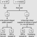
If the judgment has been made that there has been failure to progress, standing X-ray and recent magnetic resonance imaging (MRI) of the lumbosacral spine is required. Acceptable abnormalities for the performance of IDET may include disc space narrowing, disc desiccation and degeneration, or a small, contained disc protrusion. The presence of a high-intensity zone lesion does not preclude employing IDET. These images should also be scrutinized for abnormalities that could lead to the prohibition of the performance of IDET. Higher grade (II–IV) spondylolisthesis, especially isthmic and traumatic cases, will require flexion and extension plain views to rule out instability in the motion segment. Spondylolisthesis also increases the importance of ruling out nondiscogenic causes of axial low back pain. Pain greater with extension versus flexion of the spine with findings on imaging of central canal encroachment or fluid-filled zygapophyseal joints could support the diagnosis of stenosis and facet arthropathy, respectively. A positive discogram without evidence of annular disruption in the presence of a prominent Schmorl’s node may point to the node as the pain generator rather than the anulus. Short of a radical placement of the IDET catheter tip in the node itself, conventional IDET is not indicated. Performing the high heat protocol with a standard catheter placement within the anulus has been shown in a histologic study not to affect the adjacent endplate.1 Fractures of the pars, significant central canal stenosis, large disc protrusions (>5 mm extrusion beyond the posterior border of the vertebral body), extrusions, and sequestered fragments are all relative contraindications for the procedure.
Patients with prior history of fusion who return with adjacent symptomatic discs or those with multiple symptomatic levels may be suitable candidates (Table 26.2). In experience of the authors, patients tolerate single-visit, three-level IDETs without prolongation of the recovery period. Patients who have had prior partial discectomy and fusion may also be candidates though the fusion mass or instrumentation may prevent an acceptable approach to the disc. Similarly, prior chemonucleolysis, laser decompression, or nucleoplasty at the symptomatic level does not preclude IDET as long as other inclusion criteria, especially adequate preservation of disc height, are present. These intradiscal procedures may increase annular fibrosus with consequent difficulty of catheter placement.
Table 26.2 IDET Potential Indications
| SYMPTOMATIC LEVEL | |
| MULTIPLE SYMPTOMATIC LEVELS | |
The symptomatic disc should have preserved disc height >50% with reproduction of concordant pain at low pressure and volume on provocative discography. Postdiscography CT reveals an abnormal discogram with disc disruption associated with a radial tear extending to the outer anulus (see Fig. 26.13A below). Extravasation of contrast dye into the extra-annular space indicating full-thickness annular disruption is not uncommon and is not a contraindication for IDET. Patient selection should not rely solely on the results of the discogram. Discography is just one step in the evaluative process and invariably follows a thorough history and physical exam after failure to improve with rehabilitation measures.
Informed consent
It is necessary to describe to the patient potential complications including infection and nerve injury. Reassurances may be given that, by all reports, complication rates are very low.6 Saal and Saal reported no adverse events in their prospective uncontrolled study of 62 patients.7 A 2-year follow-up study by Lee of 62 patients reported no complications.8 There are anecdotal reports of bacterial discitis, thermal root injury, and catheter breakage due to kinking. One case report documents a catheter misplacement within the spinal canal resulting in cauda equina syndrome.9 Measures used to prevent these complications include sterile technique, antibiotic prophylaxis, avoidance of oversedation during the procedure, and a graduated heating protocol. Bleeding is also a concern which is addressed with documenting a normal coagulation parameters prior to the procedure.
PREOPERATIVE PREPARATION
Comorbid medical conditions must be under acceptable control. Acute infections of any type are a contraindication to the procedure. Allergies to iodine or latex should be clearly marked on the chart so that gadolinium10 and latex free gloves and syringes can be used, respectively.
PATIENT POSITION AND MARKING THE SKIN
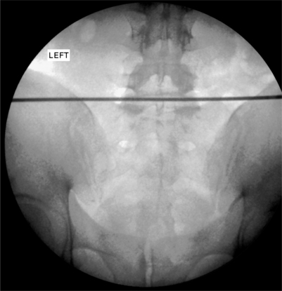
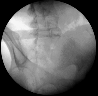
A radiopaque straight edge is then laid on top of the inferior endplate and a line is drawn across both sides of the back (Fig. 26.3). This will facilitate contralateral introducer placement and cut down on fluoroscopic exposure should a bilateral approach become necessary. Next, the camera is tilted towards the side of approach to obtain oblique views of the spine showing the classic ‘Scotty Dog’ appearance of the facet joints, pedicle, and transverse process. The camera is rotated until the superior articular process (SAP), the ‘ear’ of the dog, is approximately in the middle of the disc space (Fig. 26.4). At the L5–S1 level, the iliac crest will be obstructing the approach to the disc in this view. To open up a window, the camera needs to be rotated back towards the AP view and/or tilted in a cephalic direction until an upside-down radiolucent triangle appears composed of the edges of the superior endplate, the SAP, and the iliac crest (Fig. 26.5).
PLACING THE INTRODUCER
The introducer comes in either a beveled or diamond-shaped tip. An arrow on the hub indicates the face of the bevel. The diamond-shaped tip (Gen II – Smith & Nephew/Oratec) was developed out of concern that the bevel tip (Gen I) increased the risk of spinal nerve damage (Fig. 26.6). Both are 17-gauge with a screw-in stylet and come in 6″ and 9″ sizes. The larger size is designed for use with an extra-long catheter.
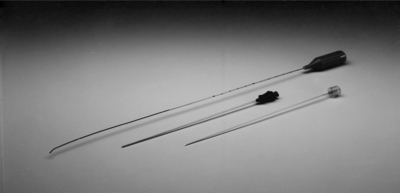
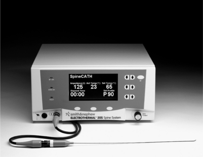
Fig. 26.6 Photo of SpineCATH, top, with Gen II 17-gauge introducer needle and screw-in stylet, bottom.
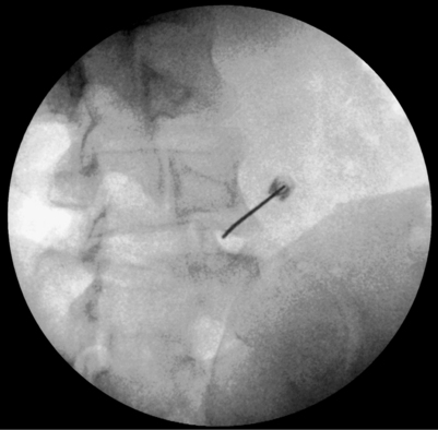
The introducer is also inserted along the angle of the camera with the bend facing the patient’s midline. The larger gauge of the introducer allows a greater feel of the tissues it passes through. The operator will be able to clearly identify dermis, subcutaneous fat, fascia, and muscle. Using the oblique fluoroscopic view as a guide, the introducer is aimed at the SAP. To avoid the exiting spinal nerve which passes laterally in oblique fashion across the superior endplate and disc, the introducer should hug the SAP’s ventral edge in order to stay medial to the nerve. To accomplish this, the needle is advanced until it gently touches down on bone. By withdrawing slightly, rotating 180° in a caudal direction away from the exiting nerve root so that the bend faces away from the spine, and readvancing, the tip can be made to slide off the ventral edge. Once it has cleared the SAP, the introducer is rotated back, again in a caudal direction, completing a turn around the facet joint (see Fig. 26.5). It is important to always rotate the needle in a caudal direction to minimize the chance of contact with the exiting nerve root.
As the tip contacts the posterior anulus, resistance to advancement will increase slightly, together with a ‘gummy’ feel indicating penetration into annular fibers. The patient may experience discomfort or pain in the form of deep localized axial back pain as the anulus is breached and this reaction can be taken as confirmatory. Reports of sharp leg pain below the knee indicates close proximity to the exiting spinal nerve. This is more likely to occur with superolateral positioning of the tip on its approach. The introducer should be withdrawn and redirected in a medial and/or inferior manner before further advancement. From this point, AP and lateral fluoroscopic views are checked frequently while advancing into the nucleus of the disc. Unlike standard discographic technique, the tip of the introducer should be placed slightly more anterior and off center so that it lies within the ipsilateral anterior quadrant of the disc. Optimal positioning will be seen as tip placement just lateral to the midline of the disc on AP and approximately three-fourths of the way across the diameter of the disc on lateral views (Fig. 26.7). This will allow for the passage of the catheter into the mid- to outer annular rings.
THREADING THE CATHETER
Before using the SpineCATH, it should be tested to ensure that it is functional. On the sterile field, connect the catheter to its cable so that the white stripe on the hub aligns with the white dot on the cable plug. There will be an audible click when the cable plug is correctly inserted into the catheter hub. The other end of the cable is handed off the sterile field and plugged into the generator. Make sure the generator is plugged in and the power is turned on using the On/Off switch on the rear panel. The thumbwheel on the rear panel needs to be set on 2 for SpineCATH procedures. (The 20S generator designed to replace the 50S has probe recognition and setting the thumbwheel is not needed [Fig. 26.8]). Check that the Actual Temperature is recording the temperature of room air (18–26°). The impedance should be between 85 and 230 ohms. Disconnect the catheter from its cable before placing it in the introducer.
The catheter is inserted into the introducer with the white stripe facing the patient’s spine. Initial AP views are best to show the catheter advancing towards the contralateral anterior anulus before turning posteriorly with the contour of the disc. It is important to make sure that the tip of the catheter exits the introducer in a manner that is parallel to the disc space (Fig. 26.9). Once tracks are made in the anulus, the catheter will follow the path of least resistance so that redirecting the catheter that is heading towards the endplate will be difficult. Any deviation of the catheter in a cephalic or caudal direction may be adjusted with rotation of the white stripe on the hub in the appropriate direction.
Again, holding the catheter by the proximal shaft as it is advanced will increase sensitivity to changes in resistance to catheter passage and reduce the incidence of kinking when obstacles are encountered. A kink is a permanent bend in the shaft of the catheter (see Fig. 26.15A below). Kinks result from continued force against resistance preventing catheter advancement. Any change in resistance should prompt a fluoroscopic view in several planes to adequately assess the advancement and position of the tip. Bowing of the catheter may occur parallel to the needle and is poorly visualized on a single plane. Typical locations of increased resistance within the disc include the posterolateral corner, the posterior midline, and sites of annular tears. Loss of resistance usually indicates escape of the catheter tip into the extra-annular or epidural space (Fig. 26.10). This occurs in excessively degenerated discs where the general integrity of the anulus is compromised. Focal annular tears can serve as paths of least resistance and may redirect the catheter along the lesion into inappropriate areas. Obstacles include the superior and inferior endplates, the anterior and posterior longitudinal ligaments, and scar tissue within the disc.
Although changing the side of approach is the most common method, there are case reports of the so-called ‘pig-tail’ technique in which a 180° redirection of the catheter is done without moving the introducer.11 The catheter is made to turn in a sharply acute angle when exiting the introducer so that it doubles back and advances in the opposite direction. The sharp turn out of the introducer gives a curled appearance reminiscent of a pig’s tail, prompting the name. This technique has the advantage of preserving a unilateral approach and avoiding the necessity of a double puncture of the posterior anulus. The acute angle between the catheter and introducer may, however, create a problem with catheter removal with increased risk for catheter shearing. Concern over these potential complications limit the use of the technique, especially in inexperienced hands.
Optimal placement of the catheter is obtained when its position is deemed adequate on two planes of view, the AP and lateral. A specialized view that somewhat replicates the axial view of the disc seen on a standard CT of the spine is obtained with extreme caudal tilt of the fluoroscopy camera. The truest axial views are seen at the lowest lumbar segments with this technique. Known as the ‘CT view,’ it is helpful in defining the extent of circumferential coverage of the anulus. The heating coil, bounded by the distal and proximal radiopaque marks, should be seen to traverse the posterior anulus and its two posterolateral corners (Fig. 26.11).
Postdiscography CTs of the target disc are helpful when assessing catheter position and should be available for review during the procedure. Lateral fluoroscopic views may show the catheter to be dorsal to the posterior edge of the vertebral bodies, raising concern for epidural placement. Lateral CTs, by showing the extent of disc bulging, can confirm safe placement within the disc. X-ray exposures of the cross-table fluoroscopic view can help to assess the location of a poorly visualized catheter and rule out placement in the epidural space (Fig. 26.12). Axial CTs may be consulted when considering placement across radial tears, especially in the hard to reach far lateral corners of the posterior anulus. If the heating coil of the catheter cannot be placed to cover the entire posterior anulus, yet covers a significant portion, consideration should be given to performing the heating protocol with the catheter in place prior to withdrawing and using a bilateral approach.
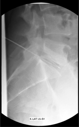
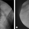
Fig. 26.12 Lateral X-ray exposure view showing catheter tip beyond posterior border of vertebral body.
The cable is reattached to the hub of the catheter. It is important to check that both radiopaque marks are clearly outside the introducer. Check that impedance is in the normal range (85–230 ohms) indicating that the power circuit is complete. Impedance should be checked periodically during the procedure. Pressing the RF button once or, if using a foot pedal, stepping on the pedal once will initiate the delivery of energy and commence the heating protocol. The generator will emit an audible tone and a blue light on the panel will light when thermal energy is delivered. It is good practice to note that Actual Temperature readings coincide with Set Temperatures. Temperature may be adjusted using the Set Temperature buttons. Note that the temperature cannot exceed peak temperature.
POSTPROCEDURE
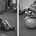
Physical therapy is not usually started before 6–8 weeks. Daily exercises initially include hamstring and piriformis stretching. Pulling the knees to the chest is done with each knee in turn as well as both together. If the patient tolerates extension and prone lying, butt/glut squeezes are performed prone over a pillow. Progression to stabilization exercises includes proper pelvic bracing while performing ‘dying bug’ and ‘superman’ routines, abdominal curls, and wall slides. Patients are encouraged to begin a graduated walking program. Backstroke-only swimming and standard stationary bike riding are also permitted. The patient is graduated to advanced stabilization exercises for the back and progressive resistance exercises for the limbs 3–4 months postoperatively. Resumption of athletic pursuits begins 4–6 months postoperatively and is graduated on an individual basis.
Case history 1
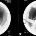
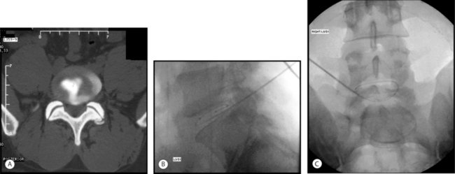
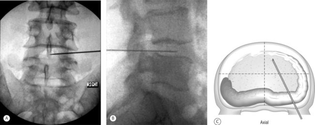
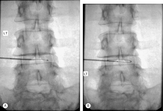
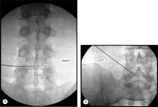
A 29-year-old man developed chronic bilateral axial low back pain following a rear-end auto accident as the seat-belted driver. He was unable to sit or stand longer than 15 minutes and ambulated with pain. MRI showed a small (<5 mm), contained central protrusion at L5–S1 without neural compression. On physical examination there was restriction in lumbosacral range of motion with a normal neurologic examination. Provocative discography reproduced severe concordant back pain with 1 cc of contrast at 15 psi. Postdiscography CT showed a posterior midline, grade III radial tear (Fig. 26.13A).
Excellent introducer placement was obtained from the right side. The catheter was directed circumferentially along the posterior anulus without obstruction or redirection. CT and lateral fluoroscopic views confirmed adequate coverage of the midline annular tear (Fig. 26.13B,C) The standard high heating protocol was performed without significant back or leg pain. At the conclusion of the procedure, the catheter and introducer were withdrawn without incident.
Case history 2
Finally, the catheter was retracted so that the tip was just contained within the posterolateral corner of the disc. The proximal radiopaque mark was concealed within the introducer in this position. The introducer was then withdrawn sufficiently to clearly reveal both marks within the disc (Fig. 26.14). A medium heating protocol was then performed beginning at 65°C and progressing to a maximum of 85°C.
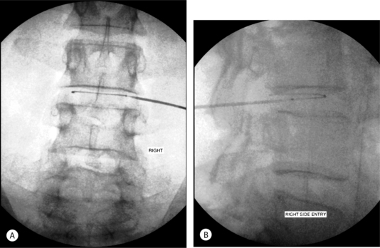
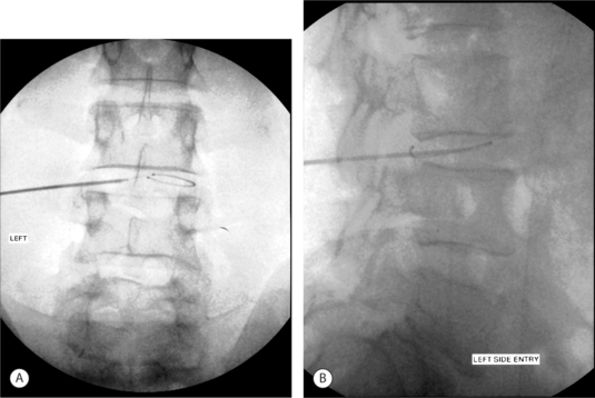
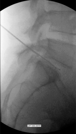
It was determined that a less than optimal coverage of the annular tear had been obtained from the right side and an approach from the left side was attempted. The catheter was threaded as far as the posterior midline before further advancement was met with insurmountable resistance. Repeated attempts to advance past the midline resulted in kinking of the catheter (Fig. 26.15A). Lateral fluoroscopic views appeared to show the catheter positioned just beyond the posterior border of the vertebral body (Fig. 26.15B). A heating protocol was begun cautiously. Within the first minute, the patient experienced sharp back and foot pain. The protocol was stopped and the procedure was discontinued. The catheter was removed via the introducer without incident.
1 Shah RV, Lutz GE, Lee J, et al. Intradiscal electrothermal therapy: a preliminary histologic study. Arch Phys Med Rehabil. 2001;82(9):1230-1237.
2 Lee J, Lutz GE, Campbell D, et al. Stability of the lumbar spine after intradiscal electrothermal therapy. Arch Phys Med Rehabil. 2001;82(1):120.
3 Marchand F, Ahmed AM. Investigation of the laminate structure of lumbar disc anulus fibrosus. Spine. 1990;15:402-410.
4 Adams P, Muir H. Qualitative changes with age of proteoglycans in human lumbar discs. Ann Rheum Dis. 1976;35:289-296.
5 Buckwalter J. Aging and degeneration of the human intervertebral disc. Spine. 1995;20:1307-1314.
6 Heary RF. Intradiscal electrothermal annuloplasty: The IDET Procedure. J Spinal Disord. 2001;14(4):353-360.
7 Saal JA, Saal JS. Intradiscal electrothermal treatment for chronic discogenic low back pain: a prospective outcome study with minimum 1-year follow-up. Spine. 2000;25:2622-2675.
8 Lee M, Lutz G, Lutz C, et al. Intradiscal electrothermal therapy (IDET) for the treatment of chronic lumbar discogenic pain: a minimum 2 year clinical outcome study. Data presented at American Academy of Physical Medicine and Rehabilitation Annual Assembly, 2003, Chicago, IL.
9 Hsia AW, Isaac K, Katz JS. Cauda equina syndrome from intradiscal electrothermal therapy. Neurology. 2000;55:320.
10 Slipman CW, Rogers DP, Isaac Z, et al. MR lumbar discography with intradiscal gadolinium in patients with severe anaphylactoid reaction to iodinated contrast material. Pain Med. 2002;3(1):1-7.
11 Narvani AA, Tsiridis E, Ishaque MA, et al. ‘Pig tail’ technique in intradiscal electrothermal therapy. J Spinal Disord. 2003;16(3):280-284.