[level-membership-for-hematology-oncology-and-palliative-medicine-category]
14 High Dose Rate Brachytherapy
Remote controlled brachytherapy can be performed using low dose rate (LDR), medium dose rate (MDR), or high dose rate (HDR) techniques. Although the International Commission on Radiation Units and Measurements (ICRU) #38 definition of HDR is >12 Gy/hr,1 the usual dose rate employed in current HDR brachytherapy units is about 100 to 300 Gy per hour. HDR has the added advantage that the treatments take only a few minutes, which can be given on an outpatient basis with minimal risk of applicator movement and minimal patient discomfort. Additionally, use of a single-stepping source, as used in most modern HDR afterloaders, allows optimization of dose distribution by varying the dwell time at each dwell position. However, it should be emphasized that, although, optimization can improve the dose distribution, it should not be used to substitute for a poorly placed implant. Nag and Samsami2 have provided examples of inappropriate optimization strategies which can lead to suboptimal dosimetry plans and clinical problems. HDR is normally given as a course of a number of fractionated HDR treatments, although it can be given as a single treatment, as in intraoperative HDR brachytherapy, if doses to the normal tissues can be sufficiently reduced by displacement or shielding. The advantages and disadvantages of HDR in comparison to LDR are enumerated in Table 14-1.
Table 14-1 Advantages and Disadvantages of High Dose Rate Compared With Low Dose Rate Brachytherapy
| Advantages | Disadvantages |
|---|---|
| 1. Radiation protection HDR eliminates radiation exposure hazard for caregivers and visitors. Caregivers are able to provide optimal patient care without fear of radiation exposure. HDR eliminates source preparation and transportation. Since there is only one source, there is minimal risk of losing a radioactive source. |
1. Radiobiological The short treatment times do not allow for the repair of sublethal damage in normal tissue, or the redistribution of cells within the cell cycle or reoxygenation of the tumor cells; hence, multiple treatments are required. |
| 2. Allows shorter treatment times There is less patient discomfort since prolonged bed rest is eliminated. It is possible to treat patients who may not tolerate long periods of isolation and those who are at high risk for pulmonary embolism due to prolonged bed rest. There is less risk of applicator movement during therapy. There are reduced hospitalization costs since outpatient therapy is possible. HDR may allow greater displacement of nearby normal tissues (by packing or retraction) which could potentially reduce morbidity. It is possible to treat a larger number of patients in institutions that have a high volume of brachytherapy patients but insufficient inpatient facilities (e.g., in some developing countries). Allow intraoperative treatments, which are completed while patient is still in the operating room. |
2. Limited experience Few centers in the United States have long-term (>20 years) experience. Until recently, standardized treatment guidelines were not available; however, the American Brachytherapy Society (ABS) has recently provided guidelines for HDR at various sites.121,122,128,130,135,147,185 |
| 3. HDR sources are of smaller diameter than the cesium sources that are used for intracavitary LDR This reduces the need for dilatation of the cervix and therefore reduces the need for heavy sedation or general anesthesia. High-risk patients who are unable to tolerate general anesthesia can be more safely treated. HDR allows for interstitial, intraluminal and percutaneous insertions. |
3. The economic disadvantage The use of HDR brachytherapy compared to manual afterloading techniques requires a large initial capital expenditure since the remote afterloaders cost about $300,000. There are additional costs for a shielded room and personnel costs are higher as the procedures are more labor intensive. |
| 4. HDR makes treatment dose distribution optimization possible Variations of the dwell times of a single stepping source allow an almost infinite variation of the effective source strengths, and the source positions allows for greater control of the dose distribution and potentially less morbidity. |
4. Greater potential risks Since a high activity source is used, there is greater potential harm if the machine malfunctions or if there is a calculation error. The short treatment times, compared to LDR, allow much less time to detect and correct errors. |
HDR, High dose rate; LDR, low dose rate.
Physics of High Dose Rate Brachytherapy
Dose Optimization for High Dose Rate Brachytherapy
Significant technological improvements have been made in imaging devices, and better quality images are now obtained. More details of the anatomy can be seen, sharper organ boundaries can be delimited, and with the development of functional imaging3; it is often possible to see tumors within organs. In parallel to modern imaging modalities, computer speed and capacity have experienced exponential growth. Visually impressive planning programs are available off the shelf and can be used to calculate dose distributions within minutes.
Inverse Planning Dose Optimization
Few algorithms that specifically use the anatomy (target and organs at risk, as well) to guide the optimization have been developed. Tumor shape and the relative positions between the organs at risk and the tumors and the intent of the clinicians all contribute to define the objectives and dose constraints of the optimization engine. One approach is to obtain an optimized plan for each set of constraints and present all the possible solutions to the planner. Then, the planner can use his or her experience or a decision-making tool to select the solution that provides the best fit for the clinical goals.4 Alternatively, one can combine the conflicting constraints as a weighted sum.5–7 This way, coverage, conformity, and uniformity of the dose distribution must be balanced for all volumes of interest, targets, and organs at risk alike. Weight factors or importance factors are used to prioritize the dose constraints. This approach, called inverse planning, has been successfully developed and implemented at the University of California at San Francisco.8–9

The minimization of the adaptable objective function requires an optimization technique that allows for wider sampling and hill climbing to escape from a local minimum. This is because of the fact that the cost function E(k) is mathematically nonlinear and therefore presents multiple minimums. Simulated annealing (SA), first introduced by Kirkpatrick,10 and other related algorithms (Fast SA, Very Fast SA) are optimization techniques that can process cost functions with arbitrary boundary conditions with the statistical guarantee of finding an optimal solution. Equally important, SA class algorithms are easily coded compared to other nonlinear optimization algorithms. It has been shown that the fast simulated annealing algorithm can be used to govern an optimization process to automatically and rapidly produce a plan for prostate permanent implant6,11 treatments, as well as for afterloading HDR prostate treatments.12
The inverse planning tool is now widely available. It was used for dose planning of several thousand patients patients8–9,12–23 with anatomic sites including prostate, gynecologic (vaginal cylinders, tandem-ovoids, and interstitial templates), rectum, sarcomas, base of tongue, and nasopharynx. In prostate treatment, the urethra can be considered a second target, because it requires the full dose but also requires protection from high dose spots. One can also include other COs such as the bulb of the penis14 and specifically protect the neurovascular bundles or boost a dominant intraprostatic lesion.
Several centers have compared the use of inverse planning with their own previous planning approaches, including geometrical optimization,8 graphical optimization,21,23 and dose point optimization.23 All those centers report a significant dosimetric advantage over other optimization techniques. The advantages include improved dose coverage, comformality and homogeneity of the target, a significant reduction of the urethra dose and of the normal tissue, as well as a reduction of the planning time.
The concept of prescribing at a given point no longer applies for inverse planning; the prescription is global. The approach of inverse planning allows the increase of the number of organs at risk with specific dose constraints without adding to the complexity of the problem. In the case of the treatment of prostate, for instance, the dose received by the bulb of the penis can be significantly reduced by including it as an additional organ at risk. It was shown that on average, the volume of the bulb receiving 75% of the prescribed dose is reduced by 80% for a small penalty of 2% on the target coverage.15
Clinical Implementation
Since CT or MRI contours of the CTV and CO are used not only to define the anatomy, but also to constrain the dose distribution, they provide the clinician with added flexibility and control to shape the dose distribution. The availability of inverse planning tools allows the planning of complex dose distributions that were not considered before. New organs at risk, not taken into account before, such as the bulb of the penis14 or the neurovascular bundles, will become an integral part of the dose constraints.
As we move from the two-dimensional (2D) brachytherapy planning system to the new 3D era, the necessity of an inverse planning algorithm becomes clear. More details can be found in Chapter 13. With hundreds of active dwell positions, irregularly shaped volumes, multiple target and organ volumes, and multiple organ sensitivities, the chance of finding dwell times that would optimally satisfy all the requirements manually becomes more and more remote. Armed with the next-generation brachytherapy planning system, systematic evaluation of partial organ tolerance on a finer scale will become possible. This understanding of partial organ tolerance will be the key to the next generation of brachytherapy.
Radiobiology of High Dose Rate Brachytherapy
Repair of Sublethal Damage
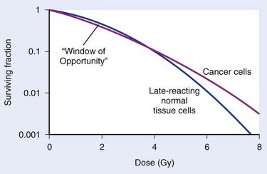
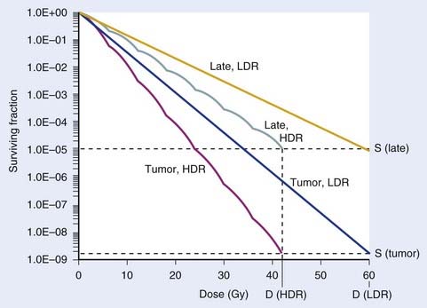
The major radiobiological difference between LDR and HDR brachytherapy relates to repair of sublethal damage. This is vitally important, because it is the differences in repair between tumor and late-responding normal tissue cells that make radiotherapy a viable way to treat cancer. These differences in repair cause the shapes of survival curves to differ, as illustrated in Fig. 14-1. Survival curves for some tumor cells tend to be flatter (more linear) and have a greater initial negative slope than those for late-reacting normal tissue cells.24 Inasmuch as survival curves for late-reacting normal tissue cells are “curvier,” they exhibit a larger shoulder at low doses which represents a greater potential for repair of sublethal damage. A fractionated course of radiotherapy capitalizes on this concept. Using multiple fractions of radiation, each of small size, allows more repair of the normal tissue compared with that of some cancer cells. There is essentially a “window of opportunity” whereby treatment at dose/fraction below the crossover point of the two survival curves in Fig. 14-1 results in more killing of tumor than normal tissue cells, and this is the reason we fractionate. It should be noted that this crossover point will be highly tumor- and normal tissue-specific, which is why the optimal dose/fraction is not the same for all clinical situations.
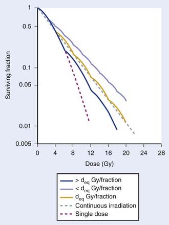
Because repair takes time, with typical half-times for repair on the order of 1 hour,25–29 it is generally agreed that at least 6 hours should be allowed between fractions if this repair advantage of fractionation is to be fully realized. Alternatively, irradiating continuously at LDR allows sufficient time during the treatment for repair to occur. Then the major radiobiologic difference between HDR and LDR is that the repair advantage with HDR is realized by using many low-dose fractions separated by enough time for most repair to occur between fractions; with LDR, the repair advantage is realized by using a dose rate low enough to allow repair during the irradiation. Replacing LDR with HDR necessitates the simulation of the dose-rate effect of LDR by the fractionation effect of HDR. This is illustrated by the cell survival curves shown in Fig. 14-2.30 The dashed line represents the single-dose survival curve at high dose rate (too high to allow any repair during the irradiation). With continuous LDR irradiation, the curve (dotted line) moves to the right (more survival) due to increased repair, and straightens out, since most repairable damage will be repaired, leaving only irreparable damage, which varies linearly with dose.31 This is the so-called dose-rate effect.31 Selecting the HDR dose/fraction that generates a fractionated survival curve that falls exactly along this continuous irradiation line achieves equivalency between the HDR and LDR regimens. This is shown by the deq Gy/fraction “wavy” line in Fig. 14-2. The “waviness” of this survival curve is a result of the repetitive shoulder for each fraction, which represents repair between successive fractions. Treating at a low dose/fraction (<deq Gy/fraction) will result in more repair and hence a shallower survival curve, as shown by the upper curve in Fig. 14-2. Conversely, treating at a higher dose/fraction (>deq Gy/fraction) causes the survival curve to become steeper.
Although Fig. 14-2 illustrates how survival curves for HDR and LDR can be similar, it does not address the important effect of the differences in shapes of the survival curves of cancer and late-responding normal tissue cells shown in Fig. 14-1. Complete equivalence of HDR and LDR regimens requires that the HDR and LDR survival curves be coincident for both tumor and normal tissue cells. Although not obvious from Fig. 14-2, it can be shown that it is theoretically possible to find a value of deq for which this will occur.26 Demonstrating this requires the use of a mathematical model that represents the shapes of these survival curves. Dale27 did just this using the linear-quadratic (L-Q) model for cell survival.
The Linear Quadratic Model
The L-Q equation for cell surviving fraction, S, is:
where d is the dose/fraction (of HDR or LDR), N is the number of fractions, α and β are parameters that define the “curviness” of the survival curves, and G is a function that accounts for the repair that occurs during and between fractions.27,32–33 Clearly, G depends on dose rate, dose/fraction, time between fractions, and the rate of repair. Dale27 published equations to account for changes in all these variables.
Using Dale’s equations, it has been shown that HDR surviving fractions can exactly match those with LDR for both cancer and normal tissue cells, with a reasonable number of HDR fractions, if it is assumed that tumor cells repair faster than normal cells.34 For example, if the half-times for repair are assumed to be 0.5 hour for tumor and 1.5 hours for late-reacting normal tissue cells,25,26,28,29 a course of 60 Gy at LDR can be matched by a 7-fraction HDR regimen at 6 Gy/fraction, using representative L-Q model α and β parameters. This is illustrated in Fig. 14-3.
Note that in Figs. 14-1 and 14-3, it has been assumed that the dose to normal tissues is the same as the tumor dose. However, a major advantage of brachytherapy is that this is a highly conformal type of radiotherapy, so the important physical advantage of brachytherapy has been neglected. This can be accounted for in L-Q model calculations by the use of the geometrical sparing factor.35
Geometrical Sparing Factor
Since brachytherapy dose distributions are significantly inhomogeneous, it is not readily obvious how to compare tumor and normal tissue doses. One way to do this is to reduce these dose distributions to “effective” doses, where the effective dose is that which, if delivered uniformly to the tumor or normal tissue, exhibits the same local control or risk of injury, respectively, as the inhomogeneous distribution it depicts.33 Then the geometrical sparing factor (f) can be defined as:
which, for brachytherapy, should normally be less than unity. This can have a profound effect on the comparison of tumor and normal tissue cell survival curves, as illustrated in Fig. 14-4, in which the tumor curve and the late-responding normal tissue curve for f = 1 (dashed) are the same as the two curves shown in Fig. 14-1, although taken out to higher doses. If, as illustrated, the dose axis represents the tumor dose, and a modest geometrical sparing factor of 0.8 is assumed, the normal tissue curve shifts 20% to the right and the crossover point moves all the way out to about 13 Gy. The “window of opportunity” now opens considerably, giving a much wider range of doses over which the repair advantage of normal tissues can be exploited. For example, using the L-Q model, one can show that with f = 0.8, the number of HDR fractions required to be equivalent to LDR (shown in Fig. 14-3) reduces from 7 to 6, and with f = 0.6, this number reduces to only 4. Hence, a modest improvement in geometrical dose sparing makes use of an HDR program practical.35–36
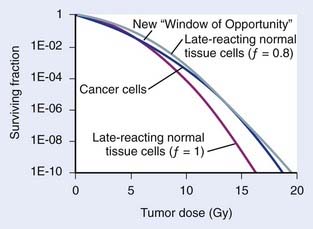
FIGURE 14-4 • Effect of geometrical sparing of normal tissues on the crossover point for tumor and normal tissue survival curves. With the L-Q model parameters used here, the crossover point moves from about 5 Gy when the geometrical sparing factor (f) = 1 (see Fig. 14-1), out to about 13 Gy when f = 0.8. Note that the “window of opportunity” now extends out to much higher doses (and doses/fraction).
Note that the cell surviving fraction curve for late reacting normal tissue cells at LDR in Fig. 14-3 was plotted using a half-time for repair of 1.5 h. However, Bentzen et al.37 have reported that their study of late reactions with continuous hyperfractionated accelerated radiotherapy (CHART) shows that this half-time for repair might well be much longer than 1.5 h, at least for some normal tissues. It has subsequently been demonstrated that geometrical sparing, combined with potentially slower repair of late-reacting normal tissue cells, could even make HDR superior to LDR.38 With this radiobiological model, the resultant calculations provide only a fair representation of the highly complex biological changes that occur in tissues exposed to a course of brachytherapy. For example, reoxygenation, repopulation, and the inverse dose-rate effect have been neglected. Nevertheless, analysis of results of several decades of experience with tens of thousands of patients treated for cervical cancer shows that replacing LDR with an HDR regimen that has four to seven fractions39 is feasible, and affirms the concordance of theory and clinical practice. In summary, radiobiological modeling shows that it is possible to replace LDR brachytherapy with HDR without a decrease in the probability of tumor control or an increased risk of complications. The number of fractions necessary to achieve equivalency between HDR and LDR regimens is multifactorial and depends on the radiobiologic properties of the irradiated tissues (e.g., the relative half-times of repair and α/β values assumed for tumor and normal-tissue cells) and the physical “geometrical sparing” of the normal tissues. Commonly used HDR regimes with four to seven fractions seem to satisfy these requirements.
Practical Use of Radiobiological Modelling for Clinicians
Fractionation schemes for HDR are widely variable, and many radiation oncologists are not very familiar with the resultant biological effects. Empirical methods such as the NSD (nominal standard dose), TDF (time-dose factor), or a dose reduction factor of 0.6 have been used in the past to convert HDR doses to LDR equivalent doses. The L-Q equation given above can be used to guide development of HDR doses and fractionation schedules. However, the L-Q mathematical calculations are tedious and may not be practical on a day-to-day basis. Hence, a simplified computer program was developed by Nag and Gupta40 to obtain the isoeffective doses to be used for HDR. The clinician needs only to enter the EBRT total dose and dose/fraction, HDR dose, and the number of HDR fractions. The program will automatically calculate the isoeffective doses for tumor and normal tissue effects. Isoeffective doses are expressed in clinically familiar terms (as if given at 2 Gy per fraction) rather than as biologically equivalent doses (BED), which are unfamiliar to clinicians. Furthermore, a dose-modifying factor (DMF) is applied to the normal tissues to account for the fact that doses to normal tissues are different from the doses to the tumor, thus, providing a more realistic equivalent normal tissue effect. This program can therefore be used to determine isoeffective HDR doses to treat various cancers. Alternatively, the program may be used to express the isoeffective dose of different HDR dose-fractionation regimes.
In view of the many limitations of the L-Q model, it must be stressed that, as with any mathematical model, the L-Q model should be used judiciously as a guide only and should always be correlated with clinical judgment and outcome results. Caution is especially warranted whenever large fraction sizes are used, since their clinical results have not been well studied.35
Clinical Uses of High Dose Rate Brachytherapy
Carcinoma of the Cervix
Role of High Dose Rate Brachytherapy
Brachytherapy is an integral part in the definitive management of cervical cancer. Traditionally, LDR brachytherapy has been used in conjunction with EBRT. More recently, HDR brachytherapy has become increasingly popular in the United States because of practical and patient care advantages. These advantages include therapy delivered solely on an outpatient basis, avoidance of long-term bed rest with its associated increased risk of deep venous thrombosis and pulmonary embolus, and avoidance of significant cervical dilation.41 Furthermore, potentially improved dose optimization to tumor exists while simultaneously sparing normal tissues (i.e., bladder and rectum) with the ability to adjust individual dwell times, and improved confidence in constant tumor coverage with more rapid delivery of treatment resulting in less risk of applicator displacement during treatment. Finally, integration of HDR brachytherapy during the course of EBRT is possible.42 A disadvantage of HDR brachytherapy for carcinoma of the cervix is the increased number of HDR treatments required to deliver doses that are equivalent to that given by LDR.
Delivery of High Dose Rate Brachytherapy
Uterovaginal Applicator
Applicator Description
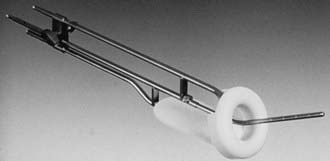
Various uterovaginal applicators are commercially available. The details of these applicators vary depending on the manufacturer. In general, delivery of HDR brachytherapy can be accomplished with the use of either tandem and ovoids (e.g., Fletcher applicator) or tandem and ring applicator. A typical tandem and ring applicator consists of three components that are interconnected: tandem, ring, and rectal retractor (depicted in Fig. 14-5). The tandem is available in three angulations (30°, 45°, and 60°) and three lengths (2, 4, and 6 cm). The caliber of the tandem is narrow and approximates the diameter of a typical uterine sound and thus obviates the need for cervical dilation for placement. The ring is available in three diameters (26, 30, and 34 mm), each with its own plastic cap (3 to 4 mm thick) and corresponding angulation (30°, 45°, and 60°) to match the tandem. An optional rectal retractor has built-in metal markers allowing easy identification of the posterior vaginal mucosa on plain radiographs and thus, facilitating dose calculation for the rectum (Fig. 14-6). These applicators are now available in a CT/MRI–compatible material to allow more accurate 3D conformal planning discussed later. The tandem is first inserted into the cervical canal followed by the ring and then the rectal retractor. The tandem, ring, and rectal retractor are interconnected, thereby ensuring that the tandem is situated at the epicenter of the ring and thus, preventing anterior or posterior displacement of the ring. Further, the fixed geometry system permits the use of preplanned dosimetry for rapid patient treatment, if required, to minimize patient discomfort.
Applicator Placement
Inserting approximately 150 to 200 mL of sterile saline solution into the bladder enhances the resolution of the ultrasound image. Gently wiggling the tandem during the imaging procedure helps to identify the tandem within the uterine cavity. Sagittal and axial images are performed to ensure there is no fundal penetration or creation of false tracts inside the uterine wall. The tip of the tandem is ideally situated within 1.0 to 1.5 cm from the fundal serosa in the normal-sized uterus (<8 cm uterine cavity length using a 6-cm length tandem). In large size uteri, the distance between the tip of the tandem and the fundal serosa may be farther in the initial application, but may decrease as the uterus size decrease with further external irradiation, chemotherapy, and HDR brachytherapy. The application placement is completed with the placement of the vaginal ring or ovoids (typically the largest size that anatomically is acceptable) and bladder and rectal retraction. If a narrowed vaginal vault does not allow optimal positioning of the ring or ovoid, an interstitial technique is preferable. In the event that an interstitial technique is not available, Sharma et al. have described an intracavitary technique which utilizes a central tandem with a single ovoid alternating with the contralateral ovoid during subsequent insertions.43 Another possibility is to use a tandem and cylinder, but this will result in a higher dose to the bladder and rectum.
Dose Prescription Points and Imaged-Based Treatment Planning
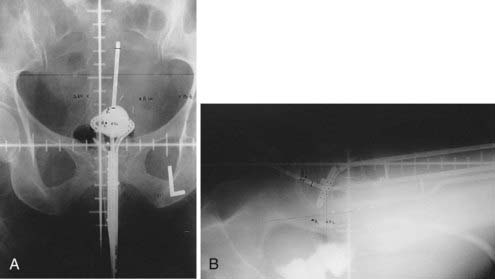
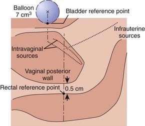
Traditionally, the dose for cervical brachytherapy has been prescribed to an applicator-based point, point A, defined as 2 cm cephalad along the axis of the tandem plus an allowance of 3 to 5 mm for thickness of the plastic cap covering and then 2 cm laterally from the axis of the tandem.44,45 Typical plain film computerized dose calculations are illustrated in Fig. 14-7. The specifications of bladder and rectal dose calculations are given in International Commission on Radiation Units and Measurements (ICRU) Report No. 38 and are illustrated in Fig. 14-8.1 The rectal and bladder doses are preferably limited to 75% of the point A dose.
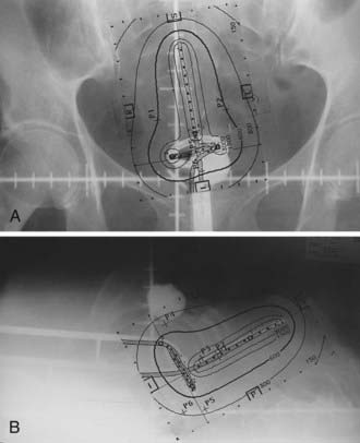
FIGURE 14-7 • Anterior-posterior (A) and lateral (B) isodose distributions of uterovaginal application.
With the advent of CT/MRI–compatible applicators, image-based treatment planning has become more feasible. MRI is superior to other current imaging modalities in delineating gross tumor involving the cervix and adjacent normal tissues.46–48 The underlying principle for using modern radiographic imaging techniques such as MRI is to potentially better delineate the target volume, which could allow dose escalation for better tumor control while simultaneously limiting dose to normal tissues. This contrasts with prescription doses that are referenced to point A, because, unfortunately, it does not necessarily reflect the dose to the tumor.
A gynecological working group was formed by the Groupe Europeen de Curietherapie and European Society for Therapeutic Radiology and Oncology (GEC-ESTRO) in 2000 to formulate and describe new terminology regarding 3D image–based treatment planning in cervical cancer brachytherapy. Their recommendations were published in March 2005 and are summarized in Table 14-2.49 This working group recognized that there is significant change of gross tumor during treatment and thus, a fluid description of treatment volumes during treatment is required to have a better understanding of dose to volume relationships and to more accurately compare treatments between institutions and patients. They devised definitions of gross tumor volume (GTV) at diagnosis and at each brachytherapy procedure as well as high risk and intermediate risk CTVs. Each of these volumes would be determined via clinical examination and MRI (preferably T2 weighted) at their respective times during the course of treatment. The CTVs are based on tumor load and represent risk of recurrence. High risk is that which includes macroscopic tumor, intermediate risk is that which includes significant microscopic disease and low risk is that which includes potential microscopic tumor spread. It is assumed that the low risk region is successfully treated with surgery and/or external beam radiotherapy.
Table 14-2 GEC-ESTRO Image-Based Planning Volume Definitions for Cervical Cancer
| Volume | Description | |
|---|---|---|
| GTVD | GTV at diagnosis | Macroscopic tumor extension at diagnosis as detected by clinical examination and visualized on MRI |
| GTVB1,B2,B3… | GTV at each BT procedure | Macroscopic tumor extension at time of brachytherapy as detected by clinical examination and as visualized on MRI |
| HR CTVB1,B2,B3… | High risk CTV at each BT procedure | Includes GTVB1,B2…, the whole cervix and presumed extracervical tumor extension at time of brachytherapy by means of clinical examination and by MRI |
| IR CTVB1,B2,B3… | Intermediate risk CTV at each BT procedure | Encompasses high risk CTV with a safety margin of 5-15 mm (Safety margin is chosen according to tumor size and location, potential tumor spread, tumor regression, and treatment strategy; the IR CTV is never less than GTVD) |
GTV, Gross tumor volume; CTV, clinical target volume; BT, brachytherapy; MRI, magnetic resonance imaging; GEC-ESTRO, Groupe Europeen de Curietherapie of European Society for Therapeutic Radiology and Oncology.
In early 2006, the working group released an update to their original recommendations to include descriptions of dose volume parameters for organs at risk and a step-wise procedure for transition from the traditional dose prescription to the 3D image–based volume prescription.50 The group recommended that for organs at risk that the minimum dose in the most irradiated tissue volumes of 0.1 cm3, 1 cm3, and 2 cm3 be reported. Ultimately, it is their intention not to alter current clinical and dosimetric reporting, but to assess the feasibility, value, and reproducibility of such volumes.
Dose Fractionation
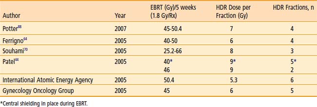
Various dose fractionation schedules have been used in the United States and worldwide (Table 14-3).45,51–54 Most commonly used regimens use fraction sizes between 5 and 7 Gy in four to six fractions, given on a weekly basis.45,55–56
Table 14-3 Carcinoma of the Cervix: Various Combined External Beam Radiation Therapy (EBRT) and High Dose Rate (HDR) Brachytherapy Regimens
When patients are treated with LDR brachytherapy, the intracavitary application is typically performed after the EBRT component to the pelvis. The use of HDR allows integration of brachytherapy earlier into the course of EBRT, typically after two weeks (20 Gy) of EBRT. The earlier integration of HDR in the radiotherapeutic management allows for the total duration of the treatment program to be shorter than eight weeks, as recommended.45 Extended duration of radiation therapy (external and brachytherapy) for cervical carcinoma beyond eight weeks is adversely associated with a lesser control rate and survival. Moreover, the earlier integration of HDR brachytherapy provides an enhanced ability to concentrate dose delivery to the primary tumor and to reduce symptoms such as bleeding. The potential disadvantage of earlier integration of HDR brachytherapy is the reduced dose to the periphery of the tumor in bulky barrel-shaped tumors (when combined simultaneously with the use of a midline bar to shield the bladder and rectum).
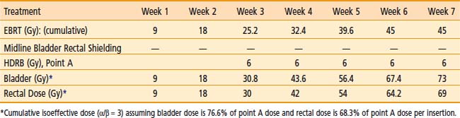
The American Brachytherapy Society (ABS) has suggested a number of therapeutic schemas for the integration of EBRT and HDR brachytherapy (Table 14-4).45 In general, a lower central dose contribution from EBRT necessitates more applicator insertions and/or increased HDR fraction size per insertion. Typical treatment scenarios are henceforth described for early stage disease and locally advanced disease. For non-bulky stages I and II (<4 cm primary) EBRT is delivered using a four-field box technique to a dose of 45.0 Gy (1.8 Gy per fraction). Following a dose of 19.8 Gy of EBRT, weekly HDR uterovaginal applications are initiated each delivering 6.0 Gy to point A. The patient would undergo a total of five HDR uterovaginal insertions and EBRT is not performed on the day of HDR brachytherapy (Table 14-5). This combination of EBRT and HDR brachytherapy would equate to a total LDR equivalent dose of approximately 84 Gy to point A.40
Table 14-4 American Brachytherapy Society Suggested Doses of External Beam Radiation Therapy (EBRT) and High Dose Rate Brachytherapy to be Used in Treating Early and Advanced Cervical Cancer
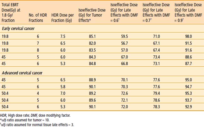
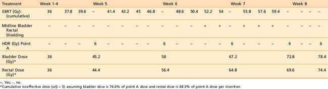
Some institutions place a midline block after 19.8 Gy of EBRT in early cases and increase the HDR doses (either additional HDR fractions or higher HDR dose per fraction). For bulky lesions (stages IB and II ≥4 cm or stages IIIA, IIIB, and IVA) anatomic distortion by the tumor may preclude the insertion of the tandem at 19.8 Gy and therefore EBRT using the four-field technique continues to 39.6 Gy and tandem insertion is reattempted. Whole pelvic EBRT is continued to a total of 45 to 50.4 Gy at which time a midline block is placed and followed by supplemental doses to the involved parametria/sidewalls to a total dose of 54.0 to 59.4 Gy with special attention given to avoiding additional small bowel irradiation. The midline block is designed to block the approximate 6 Gy isodose line. Again, five HDR applications are performed each delivering 6.0 Gy to 6.5 Gy to point A based on the whole pelvic EBRT dose (Table 14-6). With better imaging and dosimetry techniques, many centers are now using fewer fractions while increasing the dose per fraction (e.g., four fractions of 7 Gy or three fractions of 8 Gy) to obtain isoeffective doses.
Results of LDR versus HDR
The majority of published reports comparing HDR to LDR in the treatment of carcinoma of the cervix have been from nonrandomized studies, although a few randomized studies have been reported. Early studies using HDR brachytherapy demonstrated good local control and survival rates compared to LDR but with increased late small bowel complications, particularly when the HDR dose exceeded 9 Gy per fraction.57 Modifications of treatment regimens using HDR fraction doses <8 Gy to point A with an increased number of fractions have shown equivalent control rates compared to LDR without increases in toxicity.57–72
Meta-analyses and published literature reviews comparing LDR and HDR brachytherapy series have confirmed equivalency of both modalities in terms of control rate and toxicity.73,74 An analysis by Orton et al. obtained from a survey of 56 institutions demonstrated 5 year survival data available for 6939 HDR patients and 3365 LDR patients to be approximately 82% for Stage I patients and 66% for Stage II patients. For Stage III patients the 5 year survival for HDR versus LDR was 47.2% versus 42.6%, respectively.74 Fu and Phillips reached a similar conclusion in their worldwide review.75 In 1999, Petereit et al. published a literature review which included 5619 patients treated with HDR brachytherapy and demonstrated 5 year pelvic control rates of 91%, 82%, and 71% in Stage I, II, and III patients, respectively, with similar survival and complication rates to previous meta-analyses.76 Although firm conclusions cannot be drawn from uncontrolled studies, this anecdotal evidence suggests that the results of HDR are at least equivalent to those achieved by LDR brachytherapy.
Four randomized studies have compared the use of HDR with the use of LDR brachytherapy in carcinoma of the cervix.77–80 Shigematsu et al. reported on 143 patients treated with HDR brachytherapy compared to 106 patients treated with LDR for stage IIB and III disease. Although the randomization technique was suboptimal (i.e., some patients who were randomized to LDR were actually treated with HDR because of limited LDR availability) the HDR arm achieved superior local control with no difference in survival compared to the LDR arm.77 In a study from India randomizing 482 patients, there was no difference in local control, survival, or severe complications between the two treatment modalities.78 However, there was a statistical difference in rectal complications, with a 20% rate with LDR versus only 6% with HDR. In 2002, Hareyama et al. reported their results of 132 patients with stage II and IIIB cervical carcinoma.79 The 5-year disease specific survival of LDR versus HDR for stage II was 87% versus 69%, respectively and for stage IIIB 60% versus 51%, respectively; however, the difference was not statistically significant. The most recent randomized study was from Thailand in 2005 evaluating 237 patients.80 There was no difference in overall survival, relapse-free survival, pelvic control, or statistical difference in complication rates between LDR and HDR brachytherapy.
Results of Imaged-Based Treatment Planning
As the use of 3D imaging for adaptive brachytherapy treatment planning for carcinoma of the cervix has only recently emerged (although rapidly increasing), there are a limited number of published results regarding the feasibility of planning or results in regards to tumor control. The GEC-ESTRO guidelines utilize MRI as it has been shown to be superior to CT in defining tumor extension in carcinoma of the cervix.81–83 However, MRI may not be readily available at most institutions throughout the world; furthermore, MRI requires specific nonmagnetic applicators that are more expensive. In this context, Viswanathan et al. recently published their results of a standardized approach to contouring between CT and MRI after applicator insertion.84 They confirmed that CT overestimates tumor volume width, resulting in a significant decrease in dose prescription parameters compared to MRI. However, contouring and dose parameters for organs at risk were similar between the two modalities. Although recognizing that MRI is superior to CT for gross tumor delineation, they have proposed CT based volume definitions for future evaluation.
Two recent reports have demonstrated the usefulness of MRI guided optimization during pulsed dose rate brachytherapy.85,86 Lindegaard et al. evaluated 21 consecutive patients and demonstrated that MRI optimization significantly improved the minimum high risk CTV dose (D100) and decreased the minimum dose to 2 cm3 of the sigmoid compared to two dimensional planning.85 Additionally, all dose volume histogram constraints were met in 76% of patients utilizing MRI optimization, versus only 14% with 3D planning. De Brabandere et al. evaluated 16 patients utilizing MRI optimization for pulsed-dose rate brachytherapy and also demonstrated a decrease in dose to COs while increasing dose to tumor compared to x-ray based plans.86 Specifically, a dose reduction of 7 Gy was achieved to the average D2cc in the bladder (+6 Gy) and sigmoid colon (+4 Gy). Simultaneously, an average dose increase of 3 Gy to the high-risk CTV was achieved.
Inverse planning as a means of dose optimization has been integrated into the process recently but is still in its infancy of development. Chajon et al., utilizing a customized vaginal mold for thirty patients, calculated dose distribution using inverse planning simulated annealing (IPSA) software.87 Inverse planning provided significantly lower doses to the ICRU bladder and rectal points compared to manual optimization methods. Although inverse planning was found to be a fast method, they cautioned its widespread use, because the optimization resulted in significant heterogeneity in dwell times. Kubicky and colleagues developed a novel technique to avoid the registration errors of MRI-CT fusion for treatment planning by using gadodiamide-filled plastic tubes inserted into the ring and tandem applicator during acquisition of the MRI to visualize the source pathway.16 An evaluation of 15 consecutive women using this novel technique along with IPSA resulted in a mean D90 of 86 Gy to the HR-CTV while maintaining a mean D1cc of 78 Gy to the bladder and 70 Gy to the rectum.
The Medical University of Vienna reported in 2007 their results of 142 out of 145 consecutive patients with Federation International de Gynecologie et d’ Obstetrique (FIGO) Stage IB-IVA, treated using MRI adaptive strategies.88 A total of 420 MRI examinations with 3D planning were performed. The latter 72 patients (period from 2001 to 2003) were planned utilizing the current GEC-ESTRO guidelines of tumor contouring and a mean D90 (dose to 90% of the high risk CTV) of 90 Gy was achieved. Continuous complete remission was 96% for patients with tumors sized 2 to 5 cm and 90% for patients with tumors sized greater than 5 cm. 95% of patients achieved complete remission with an overall 3 year progression free survival of 85%. Severe late side effects were 2% in this latter group of patients. To further validate these results, a prospective observational multicenter trial (the EMBRACE study) was started in Europe in 2008.
Carcinoma of the Endometrium
Adjuvant Radiation Therapy
High dose rate brachytherapy (either as a sole modality or as a boost to EBRT) is commonly used to treat the vaginal cuff after hysterectomy in patients with intermediate to high risk for vaginal recurrence. Indications may include high-grade adenocarcinoma histology, deep myometrial invasion, and extrauterine (including lymph node metastases) or cervical spread. The role of EBRT and/or vaginal cuff brachytherapy in endometrial carcinoma following hysterectomy in stage I disease remains controversial. The Post Operative Radiation Therapy in Endometrial Carcinoma (PORTEC) I study, originally published in 2000 (with a 10 year follow-up published in 2005), along with Gynecological Oncology Group (GOG)-99 (published in 2004), helped better define a population at an elevated risk of recurrence to support the use of adjuvant EBRT.89–91 PORTEC I randomized patients with superficial myometrial invasion (<50%) and FIGO grade 2 or 3 disease or deep myometrial invasion (>50%) and FIGO grade 1 or 2 disease to observation or whole pelvic EBRT following surgical resection.89–90 GOG-99 randomized Stage IB, IC, and occult II patients to the same therapy.91 Both studies demonstrated a decrease in local regional recurrence with EBRT (3% to 5% versus 12% to 14%) without showing an overall survival advantage. As the majority of recurrences have been located in the vagina, the PORTEC II trial was undertaken to evaluate whether adjuvant vaginal cuff brachytherapy alone could adequately replace pelvic EBRT in regards to recurrence risk, potentially improving patient’s quality of life. Eligible patients included those older than 60 years of age with FIGO stage IC grade 1 to 2 or stage IB grade 3 or those of any age with FIGO stage IIA grade 1 to 2 or grade 3 with <50% invasion. The results of the study were presented in abstract form at the 2008 American Society of Clinical Oncology annual meeting.92 With a median follow-up of 34 months 3-year actuarial rates of vaginal relapse were 0.9% in the vaginal brachytherapy group and 2.0% following EBRT. Pelvic relapse at 3 years was statistically significantly higher in the vaginal brachytherapy group with a rate of 3.6% versus 0.7% in the EBRT group. However, there were no significant differences in 3-year overall survival and recurrence free survival. Based on the data from PORTEC-2, the authors concluded that vaginal brachytherapy was a safe and reasonable alternative to EBRT, and affects QOL significantly less than EBRT; hence vaginal brachytherapy should replace pelvic EBRT in this setting. Although the options of EBRT alone, vaginal brachytherapy alone, or a combination of both exist for stage I disease, the ultimate choice requires clinical judgment regarding risk of locoregional recurrence, morbidity, costs of adjuvant therapy, and potential for salvage of patients with vaginal recurrences.
Technique of Vaginal Brachytherapy
If pelvic EBRT is given, the dose is usually about 40 to 45 Gy in 20 to 25 treatments, respectively. Brachytherapy is usually performed by a single-line source placed centrally in a vaginal cylinder. A gold fiducial marker is placed at the beginning of the procedure to indicate the position of the vaginal vault on radiographs. The largest diameter of a cylinder that comfortably first the vagina is used. Vaginal cylinder diameters of less than 3 cm are to be avoided, if possible, because of the decreased depth dose obtained with a small source to vaginal surface distance. The superior portion of the vagina (3 to 5 cm) is usually treated in most cases, although a longer length (about 8 cm or entire length of vagina) is preferable in clear cell or serous histologies.93–106
A single iridium-192 linear source, as used in a vaginal cylinder, has the potential for dose inhomogeneity at the vaginal apex due to source anisotropy. The actual clinical significance of dose anisotropy is not well defined. Some centers prefer to use an angled source, an ovoid, circular ring, or multichannel applicator to circumvent this potential problem.103
Brachytherapy Dose
The dose prescription point is either defined at the vaginal surface or at 0.5 cm from the surface of the vaginal cylinder. In either case, both doses (vaginal surface and 0.5 cm depth) are to be recorded as recommended by the ABS.103 It is not recommended to use 1.0 cm vaginal depth as a prescription dose point. The dose per fraction has varied from 4.5 to 16 Gy, and the number of fractions has varied from 2 to 7.93–102,104–108 The interval between fractions is usually 1 to 2 weeks, but more commonly once weekly. When a lower dose of about 5 Gy per fraction is chosen, a larger number of fractions is used (3 or 4) or EBRT is added, or both. The consensus report also advises the use of dose optimization for the cylinder or an angle source delivery system to be introduced to ensure uniform dose at depth and eliminate the potential dose reduction at the vaginal apex due to source anisotropy.103 The dose distribution should be optimized to deliver the prescribed dose either at the vaginal surface or at 0.5 cm depth, depending on the institutional policy. It is important to place dose optimization points not only along the lateral aspect of the vaginal wall but also at specified points about the dome of the vaginal cylinder to avoid higher vaginal apex doses which can lead to vaginal vault necrosis.2
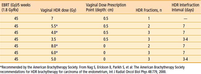
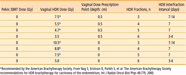
Commonly used regimen combining EBRT and HDR brachytherapy include the following: 45 Gy in 25 fractions of EBRT (four-field box technique); one, two, or three fractions of HDR spaced one week apart delivering 7 Gy, 5.5 Gy, or 4.0 Gy each, respectively, prescribed at 0.5 cm depth administered at the completion of EBRT. This allows for completion of the treatment program combining EBRT and vaginal brachytherapy within 7 weeks. A tabular summary of the treatment parameters combining EBRT and vaginal brachytherapy in the adjuvant setting is given in Table 14-7. For adjuvant vaginal HDR brachytherapy alone, a dose of 21 Gy (at 0.5 cm depth) given in three treatments spaced 1 to 2 weeks apart is commonly used and was the recommended dose in the previously mentioned PORTEC-2 trial. The ABS has made recommendations for both prescription points (0.5 cm depth, vaginal surface) (Table 14-8).
Results and Morbidity
The 5-year survival results vary from 72% to 97%, depending on the usual prognostic parameters such as stage, grade, and depth of myometrial invasion.93–97,99–102,104–111 The severe (Grade III or IV) late complication rate is usually <2% and depends on the dose per fraction.93–101,104,106,107,112 Generally, doses per fraction of more than 7 Gy should be avoided (especially if EBRT is added). The incidence of vaginal shortening is also very much dose dependent, reportedly as high as 70% when 9 Gy per fraction was prescribed at 1 cm depth, to 31% when the dose was reduced to 4.5 Gy per fraction.98 The lower doses per fraction are usually given using either a larger number of fractions or in combination with EBRT to the pelvis. Sorbe et al. evaluated two different fractionation schemes (2.5 Gy × 6 versus 5 Gy × 6) in a randomized trial and found no difference in locoregional recurrence rates, but an increase in vaginal shortening, mucosal atrophy, and bleeding in the 5 Gy per fraction arm.113 Other factors that increase morbidity include the use of a small (2 cm) diameter vaginal cylinder, the addition of pelvic EBRT, and a dose specification point beyond 0.5 cm.93 Pearcey and Petereit published a literature review analyzing 1800 cases of postoperative HDR brachytherapy alone in patients with low to intermediate risk endometrial cancer.114 They found an overall vaginal control rate of 99.3%. Late morbidity was significantly higher with isoeffective doses for late responding tissues exceeding 100 Gy.
Inoperable Endometrial Carcinoma
Indications
Some patients with adenocarcinoma of the endometrium are not candidates for surgery because of severe comorbid medical problems (obesity, cardiovascular disease, diabetes mellitus, and hypertension). This subset is treated by radiation therapy. A combination of EBRT and brachytherapy or brachytherapy alone is used depending on the size of the uterine cavity, histologic grade, and other risk factors for lymph node involvement. The previously mentioned conditions that preclude these patients from surgery also place them at added risk for anesthesia and prolonged bed rest. Hence it is preferable to avoid LDR brachytherapy in this circumstance since the incidence of thromboembolic events and cardiac decompression may be significant when LDR brachytherapy is used.41
Technique
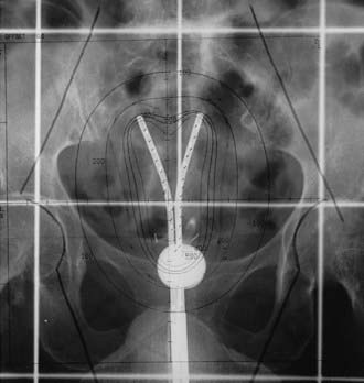
Various applicators can be used for treatment of primary endometrial cancer. A tandem and colpostat is often used; however, this applicator will not irradiate the uterine fundus homogeneously. Others have used a curved tandem, turning it to the left and right in alternate insertions. A Y-shaped applicator, comprising two abutting tandems, irradiates the fundus more evenly by allowing the tip of each tandem to lodge in each cornu (Fig. 14-9). Other possibilities include modified Heyman capsules or multiple tandems.109 The dose is commonly specified at 2.0 cm caudally from the fundus (at the midline) and 2 cm laterally, although CT or MRI based treatment planning to ensure a more homogeneous dose to the entire myometrium is preferred.
Dose Schedules
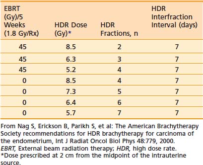
The dose per fraction has ranged from 5 to 12 Gy, and three to six fractions are commonly employed.94–95,109,115–126 The dose and/or the dose per fraction are reduced if EBRT can be added. The ABS suggested doses for HDR brachytherapy alone or in combination with 45 Gy EBRT are given in Table 14-9.103
Results
The survival at 5 years for stage I is about 70% to 80%, which is slightly lower than that obtained by surgery. A recent report by Coon and colleagues with a median follow-up of 33 months reported a 5-year cause-specific survival of 87% for patients treated with HDR twice daily with 35 Gy in five fractions without EBRT or with 20 Gy in five fractions with EBRT.127 The toxicity is higher (about 7%) when patients are treated with high doses per fraction.118,125–126
Treatment of Vaginal Recurrence
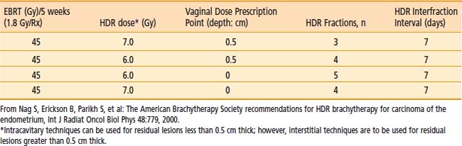
The radiotherapeutic treatment of vaginal recurrences following definitive surgical therapy for endometrial carcinoma has generally achieved modest results.128 The salvage rate for isolated vaginal recurrences is 40% to 80%.129–131 The treatment consists of combined pelvic EBRT (45 Gy in 5 weeks) integrated with vaginal brachytherapy. Vaginal intracavitary brachytherapy should be used selectively for residual masses less than 0.5 cm in thickness. Interstitial brachytherapy should be performed for bulkier vaginal residual tumors following EBRT or for previously irradiated (with EBRT) patients. A tabular list of ABS treatment guidelines using HDR brachytherapy is presented in Table 14-10.103
Lung Cancer
Indications
Goals and indications for HDR endobronchial brachytherapy include132–136:


Although the role of HDR endobronchial brachytherapy is primarily palliative, its routine use as a boost for EBRT or as an adjunct to surgery has not been well established in patients treated for cure and awaits further clinical trials.136–140 However, some centers have used endobronchial HDR brachytherapy in patients with inoperable lung cancer, early-stage medically inoperable patients, or as adjuvant treatment in cases with minimal residual disease after surgical resection.140–153 Initial endobronchial brachytherapy may help to open up an obstructed bronchus, alleviating postobstructive pneumonia and thereby help to define the field for EBRT. HDR brachytherapy can also be used after EBRT to increase the chances of a cure. It is important to recognize that the limited penetration of dose of endobronchial HDR brachytherapy requires the careful selection of patients with predominant endobronchial tumor. Bulky extrinsic peribronchial disease beyond 1.5 to 2 cm from the source catheter will not be significantly affected by HDR endobronchial brachytherapy.
Localization Radiographs
Localization x-ray films, with radiopaque dummy wires in the catheters, should be obtained with an orthogonal technique, the three-film method, or special localization jigs.154 Alternatively, many centers now use CT simulation nowadays. The location of the lesion and the target length are marked to determine the length to be irradiated and the proximal/distal dwell positions.
Treatment Planning
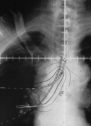
The radiation oncologist advises the physicist or dosimetrist of the treatment parameters including dose, prescription point, length, location, and number of catheters to be irradiated. The dose is commonly prescribed to 1.0 cm from the source.155–156 The length to be irradiated usually includes the endobronchial tumor and a 1.0 to 2.0 cm margin, both proximally and distally, which typically represents a 5 to 7 cm bronchial segment. Fig. 14-10 provides an illustrative case using two catheters. Some centers use an abbreviated, preplanned dosimetry based on precalculated plans for various lengths of irradiated bronchial segments. The prescribed dose of 5 or 7.5 Gy at 1 cm from the source using equal times is used for single catheter placements with minimal curvature. This simplified dosimetry shortens considerably the waiting time between catheter placement and actual treatment delivery.40 Individualized image-based planning is recommended for multiple catheter placements.
Dose and Fractionation
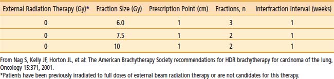
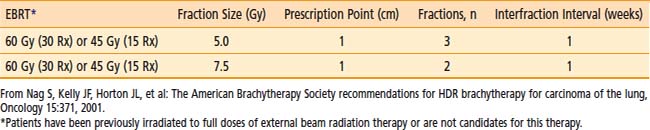
Although various dose schedules have been used ranging from 15 Gy in 1 fraction to 20 Gy divided into five fractions, the most commonly used interval between fractions is one week and the fraction size is typically between 5 Gy (repeated 3 or 4 times) and 10 Gy (repeated twice).156 The ABS recommends several regimens including three 7.5 Gy fractions (weekly), two 10 Gy fractions (weekly), or four fractions of 6 Gy all prescribed at 1.0 cm when used as a solitary modality for palliation (Table 14-11).135 When used as a boost to EBRT (60 Gy in 30 fractions or 45 Gy in 15 fractions), the ABS recommends an HDR dose of three 5 Gy fractions (weekly) or two 7.5 Gy fractions (weekly) also prescribed at 1.0 cm from the central axis of the catheter (Table 14-12).135 There are no convincing data to suggest clinical superiority of any singular regimen. In the rare case of endobronchial brachytherapy used as a sole treatment modality in previously unirradiated patients, HDR doses of five 5 Gy fractions or three 7.5 Gy fractions are advised by the ABS.135
Clinical Results
Benefits of Palliative Intent HDR Brachytherapy
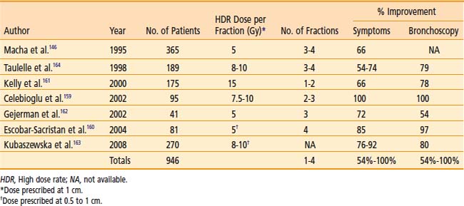
The clinical results obtained by a number of institutions indicate subjective improvement rates of 50% to 100% and bronchoscopic objective response rates of 59% to 100%.140,142,146,157–164 There is an inherent difficulty in analyzing the reasons for the variability of results because of different study designs: the inhomogeneous groups of patients; treatment of advanced tumors; the use of additional treatments (including lasers, EBRT, previous therapy); and the variety of dose and fractionation schedules used. Table 14-13 is a summary of recent published series on palliative endobronchial brachytherapy.
Benefits of Curative Intent HDR Brachytherapy
Select patients with predominantly endobronchial disease who are candidates for EBRT with chemotherapy may receive an endobronchial boost using HDR brachytherapy to achieve rapid improvement of severe bronchial symptoms or obstructive pneumonitis or both.139–143,145,148,149 Muto et al. performed a nonrandomized prospective study evaluating three endobronchial brachytherapy schemes concomitantly with EBRT on 320 patients with advanced inoperable non–small cell lung cancer.149 Endobronchial brachytherapy consisted of either 10 Gy in one fraction, 14 Gy in two fractions, or 21 Gy in three fractions. Median survival for all patients was 11.1 months with a symptomatic response rate ranging from 82% to 94%. Complications were the least in the group of patients receiving 21 Gy in three fractions.
An uncommon clinical scenario is the patient with an occult endobronchial or tracheal lesion who can be treated with endobronchial HDR brachytherapy alone or in combination with EBRT. Encouraging results have been published in a small series of patients indicating cause-specific survival between 51% and 100%.144,150–153 Hennequin et al. published updated results of 106 patients treated with either six fractions of 7 Gy each (before 1994) or 5 Gy each (after 1994) to a depth ranging from 0.5 cm to 1.5 cm.153 Factors associated with increased rates of local failure included tumor length >2 cm, bronchial obstruction >25%, visible tumor on CT, and previous endoscopic treatments.
A report of endobronchial HDR brachytherapy as a sole treatment modality for early-stage disease in medically inoperable patients by Marsiglia et al. indicates a survival of rate of 78%. The median follow-up was 2 years among this series of 34 patients. The regimen used was 30 Gy in six fractions of 5 Gy each once weekly.147 Endobronchial HDR brachytherapy may be used for minimal bulk residual disease after surgical resection. Macha et al. have reported on 19 patients treated with 5 Gy fractions (total 20 Gy) with favorable results.146
Complications
Radiation bronchitis and stenosis are occasionally seen after HDR endobronchial brachytherapy.165 Since the dose is typically prescribed at 1 cm from the radiation source, narrower airways (i.e., distal) may be expected to receive higher bronchial mucosa doses. Other contributing factors such as tumor destruction of the bronchial wall remain unclear. Radiation bronchitis can vary from grade I (mild mucosal inflammation), which invariably occurs, to grade IV. Grade IV is characterized by significant fibrosis that results in circumferential narrowing, requiring dilation or stent placement. Speiser and Spartling165 reported an overall incidence of 29%, 22%, 20%, and 29%, respectively, for grades I through IV radiation bronchitis.
The serious complication of fatal hemoptysis may result from soft tissue destruction caused by the high dose of radiation delivered to the area of the pulmonary artery, or the failure of treatment to control tumor with resultant progression of disease.166 Significant risk factors for the development of fatal hemoptysis may include a heavy pretreatment dose of external beam irradiation, multiple courses of endobronchial brachytherapy, a left upper lobe bronchial location, or long irradiated bronchial segments.167,168 Reports of the incidence of fatal hemoptysis vary considerably in range—zero to 50%, with a median value of 8%.136
New Approaches
Utilization of HDR brachytherapy following sublobar resection for those patients with poor pulmonary function not amenable to lobectomy has recently been described. McKenna et al. reported their series of 48 patients who underwent wedge resection, lymph node dissection and brachytherapy.169 Brachytherapy consisted of seven fractions of 350 cGy each prescribed to a depth of 1 cm delivered twice daily. Four recurrences were recorded with follow-up ranging from 1 to 27 months.
Allison and colleagues reported the use of a metallic stent placed in the endobronchial lumen followed by HDR brachytherapy of three fractions each of 6 Gy prescribed to a depth of 0.5 cm over a 2-week period for palliative purposes.170 They noted a significant improvement in Karnofsky performance status and pulmonary palliation.
Finally, the use of HDR brachytherapy in combination with photodynamic therapy (PDT) or yttrium-aluminum-garnet (YAG) laser has been described. Freitag et al. reported results from 32 patients with bulky endobronchial non–small cell lung cancer treated initially with PDT followed 6 weeks later with five fractions (one per week) of 4 Gy each prescribed at a distance of 1 cm.171 Eighty-one percent of patients were free of endobronchial tumor at a mean follow-up of 24 months. Chella et al. performed a small randomized trial comparing YAG laser alone versus YAG laser plus HDR brachytherapy in 29 patients.172 HDR brachytherapy consisted of 3 fractions (one per week) of 5 Gy each prescribed at a distance of 0.5 cm. Combination therapy resulted in a statistical improvement in period free from symptoms from 2.8 months to 8.5 months. Disease progression–free period improved from 2.2 months to 7.5 months as well.
Cancer of the Esophagus
Indications
The development of a successful combined modality regimen (concurrent radiation and chemotherapy)173 has renewed interest in improving local control of esophageal cancer. Despite the use of EBRT and concurrent chemotherapy, local failures occur in 30% to 40% of cases. HDR brachytherapy has been used either alone or in combination with EBRT, both for palliation and for potential cure as a boost treatment following EBRT. The palliative role of HDR brachytherapy alone is well established, but the potentially role of HDR brachytherapy as a boost following EBRT and concurrent chemotherapy remains to be defined.
Technique
The treatment is usually given via a nasogastric tube or a special esophageal applicator. Fig. 14-11 provides an example of such an application. The largest possible diameter applicator that can be easily inserted should be used to minimize the dose to the mucosa relative to the dose at depth. However, the standardization of applicator diameter has not been established.174 The site to be irradiated can be confirmed by fluoroscopy or endoscopy. Usually, the area involved by tumor with the margin of 2 cm cephalad and 2 cm caudad is treated.

Dose and Fractionation
The dose is generally prescribed at 1 cm. Doses of 5 to 15 Gy per fraction have been given for one to four fractions either alone or before, concurrent with, or after EBRT. The advantage of giving brachytherapy after EBRT is to allow shrinkage of the tumor to deliver a more uniform dose to the residual tumor. The advantage of giving the brachytherapy initially is to have rapid relief of the major symptom, dysphagia. The ABS currently recommends an HDR dose regimen of two fractions of 5 Gy each prescribed at 1 cm from the source for a total of 10 Gy. An esophageal applicator with an external diameter of 6 to 10 mm should be used. EBRT delivering 50 Gy in 5 weeks and concurrent chemotherapy should precede the dose.175 Hence, the brachytherapy component is delayed until radiation therapy and chemotherapy are completed. HDR brachytherapy at doses of 16 Gy in 2 treatments or 18 Gy in three treatments have been used without additional EBRT to palliate esophageal cancers.176,177
Clinical Results
Sur et al. reported the results of a randomized trial of 50 patients showing a 1-year survival benefit (69% versus 16%) and improvement in dysphagia at 3 months (82% versus 24%) and at 6 months (84% versus 13%) in patients receiving EBRT (35 Gy in 15 fractions) followed by HDR brachytherapy of 12 Gy in 2 fractions compared to the same EBRT alone.178 A multicenter prospective randomized study conducted under the auspices of the International Atomic Energy Agency (IAEA) evaluated two HDR regimens in 232 patients. One hundred seventy-seven patients were randomized to receive 18 Gy in 3 fractions or 16 Gy in 2 fractions. The dysphagia-free survival and overall survival for the whole group was 7.1 months and 7.9 months, respectively. The incidence of strictures and fistula formation was approximately 10% in both groups. The authors concluded that dose fractions of 6 Gy × 3 and 8 Gy × 2 within 1 week give similar results for dysphagia-free survival, overall survival, and incidence of strictures and fistulae.
Sur et al. reported another randomized trial comparing 16 Gy in 2 fractions over a 3 day period followed by observation versus the same HDR regimen followed by EBRT of 30 Gy in 10 fractions.179 At 12 months there was no difference in dysphagia free survival, overall survival, or incidence of strictures and fistula formation between the two groups. This led to a randomized, international multi-institutional IAEA trial with 219 patients that has recently been reported in an abstract.180 Patients received two HDR brachytherapy of 8.0 Gy each, at 1 cm from the source centre, and were randomized to EBRT of 30 Gy in 10 fractions versus no EBRT. The main outcome of dysphagia-free experience (DFE) was significantly improved with EBRT, by an absolute 18%. Mean dysphagia scores, mean regurgitation scores, performance status and some quality of life measures were significantly improved with the addition of EBRT. Adverse events (e.g., perforations, ulcers) were not statistically different between the two study groups. Overall median survival was 188 days; with no difference between study arms. The authors concluded that the addition of EBRT to HDR improves palliation in patients with squamous cell carcinoma of the esophagus.
Evaluation of HDR brachytherapy in addition to the current standard of care of concurrent external radiation therapy and chemotherapy has been evaluated in phase I/II studies with conflicting results. The multi-institutional Radiation Therapy Oncology Group (RTOG) 92-07 phase I/II study of EBRT, brachytherapy, and concurrent cisplatin and 5-flurouracil obtained a 12% incidence of fistula formation which led to 3 deaths among the 49 entered patients.181 The median survival was 11 months and local persistence or recurrence was 63%. In a follow-up analysis, 92% of surviving patients were able to swallow at least liquids at some point after therapy.182 A recently reported phase II study from Germany using a concomitant boost technique with EBRT (64.8 Gy) concurrent with cisplatin and 5-flurouracil followed by endoluminal HDR brachytherapy of 2 to 3 fractions of 6 Gy, each beginning during week four of therapy, demonstrated a median overall survival of 16 months.183 They also reported an overall 12% incidence of fistula formation; however 4% was non–tumor related, and no deaths were recorded as a result. This may be attributed to the earlier integration of brachytherapy into the treatment regimen and/or use of a larger diameter (10-mm) applicator compared to the timing and applicator used in RTOG 92-07. Vuong et al. from McGill University reported the use of neoadjuvant HDR brachytherapy of 20 Gy in five fractions followed by EBRT (50 Gy) and concurrent cisplatin and 5-fluorouracil (5-FU).184 Median overall survival was 21 months with a 2 year local recurrence rate of 25%. Only one patient (1.4%) developed a fistula and dysphagia was relieved in 90% of patients following the second or third HDR application. Although the last two studies show promising results with limited toxicity, caution should be exercised in the use of concurrent EBRT, chemotherapy, and brachytherapy.
Carcinoma of the Prostate
Currently, permanent implantation of iodine-125 or palladium-103 seeds is the most common type of prostate brachytherapy. HDR brachytherapy as a boost to EBRT for localized prostate cancer has been well defined and is being used more commonly. Its use as monotherapy is emerging and initial results are promising. For recurrent disease after radical prostatectomy, further studies are needed to more clearly define the role of HDR brachytherapy. One of the major advantages of HDR is that the dose distribution can be intraoperatively optimized by varying the dwell times at various dwell positions in addition to varying the needle positioning,185 potentially allowing reliable and reproducible delivery of the prescribed dose to the target volume while keeping the doses to normal structures (rectum, bladder, and urethra) within acceptable limits. Another potential advantage of HDR brachytherapy in prostate cancer is the theoretical consideration that prostate cancer cells behave more like late reacting tissue with a low α/β ratio and they should, therefore, respond more favorably to higher dose fractions rather than to the lower dose rate delivered in LDR brachytherapy.186–187 The role of prostate HDR brachytherapy is discussed in detail in the prostate chapter of this book and is briefly summarized elsewhere.
HDR Prostate Brachytherapy as a Boost
Indications
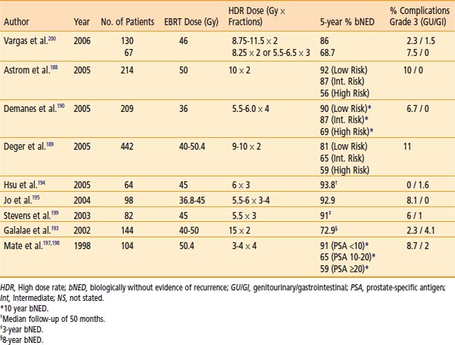
Several centers have used HDR brachytherapy as a boost to EBRT for the treatment of prostate cancer with encouraging results (Table 14-14).188–199 Patients with stages T1b to T3b prostate cancers without evidence of distant metastases are candidates for HDR brachytherapy as a boost to EBRT. Patients with distant metastases, a life expectancy of less than 5 years, or those who are medically unfit for anesthesia or in whom it is technically not feasible to implant the entire prostate should be excluded. Relative contraindications include large gland size (>80 cc), recent transurethral resection of prostate (TURP) within the last 6 months or large TURP defects, all of which increase the risk of urinary morbidity.
Dose and Fractionation
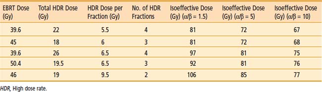
Standard fractionation EBRT (39.6 to 50.4 Gy) is given before, concurrently with, or after HDR brachytherapy. The minimum volume treated should include the entire prostate and seminal vesicles with a margin, with or without pelvic lymph nodes. The HDR dose is given in multiple fractions in one or two implant procedures. A variety of dose and fractionation schemes may be appropriate for same-stage disease as shown in Table 14-15.188,192,196–198 The HDR fractions are generally given twice a day, with a minimum of 6 hours between fractions.
Results
Galalae et al. reported results from 611 patients (some of which are included in Table 14-15) treated at three institutions (Kiel, Germany; William Beaumont Hospital; Seattle Prostate Institute) with EBRT and HDR brachytherapy for localized prostate cancer.193 Different fractionation schemes were used as seen in Table 14-15. Five-year biochemical control for low risk, intermediate risk, and high risk patients was 96%, 88%, and 69%, respectively.
William Beaumont Hospital initiated a phase I/II study in 1991 of HDR brachytherapy boost for patients with intermediate and high risk prostate cancer and have updated their results periodically. All patients received 46 Gy of EBRT to the pelvis and then various HDR fractionation schedules ranging from three implants of 5.5 Gy to 6.5 Gy each or two implants of 8.25 Gy to 11.5 Gy each. Patients were analyzed by separating them into two dose groups: low dose (88.2 Gy) and high dose (116.8 Gy). As of 2006, with a median follow up of 4.9 years which included 197 patients, the 5-year biochemical failure (68.7% versus 86%), clinical failure, clinical event–free survival, cause-specific survival, and overall survival (86.2% versus 97.8%) favored the high-dose group.200
A phase III randomized study was performed in the United Kingdom evaluating EBRT versus reduced dose EBRT with HDR brachytherapy.201 Eligible patients included all stages of localized prostate cancer, prostate-specific antigen (PSA) test <50, and Gleason score from 5 to 8. EBRT alone consisted of 55 Gy in 20 fractions and combined treatment consisted of EBRT of 37.5 Gy in 13 fractions with HDR single implant delivering 17 Gy in two fractions in 24 hours. With a median follow-up of 30 months, there was a significant biochemical relapse–free survival favoring combined treatment. Acute and late toxicities were similar between the two groups, with a lower incidence of acute rectal discharge in the combined treatment group. Although there are flaws in the trial including potential low dose of definitive EBRT, variety of eligible patients, relative short follow-up, and nonconsistent use of anti-androgen therapy, the trial highlights that HDR brachytherapy is indeed feasible, with good cancer control outcomes and low morbidity.
HDR Prostate Brachytherapy as Monotherapy
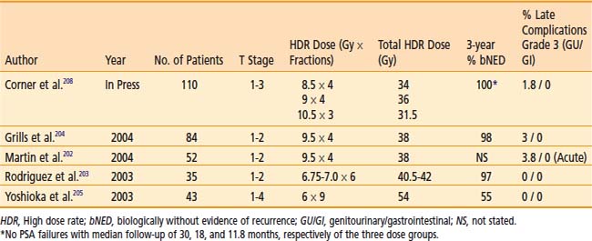
HDR brachytherapy is also being used as monotherapy in a few centers, but long-term results are not yet available (Table 14-16).202–205 HDR doses of 38 Gy delivered in four fractions, two times daily over 2 days or 54 Gy in 9 fractions given twice a day over 5 days have been reported.204–207 Grills et al. compared 149 patients with localized prostate cancer treated with interstitial HDR brachytherapy versus permanent implant in a retrospective analysis.204 HDR brachytherapy was delivered in four fractions for a total dose of 38 Gy. Biochemical no evidence of disease at 3 years was 98% and 97% for HDR and permanent implant, respectively. In those patients treated with HDR, they noted statistically significant decreased rates of acute RTOG Grade 1 to 3 dysuria, urinary frequency/urgency, and rectal pain, as well as chronic urinary frequency. There was no difference in chronic dysuria, urinary incontinence, retention, or hematuria between the two groups. The 3-year impotence rate was less for patients treated with HDR (16% versus. 45%). Urinary stricture rates were higher in patients treated with HDR; however this was not statistically significant. Rodriguez et al. reported preliminary results of 35 patients with low- to intermediate-risk prostate cancer treated with HDR monotherapy delivering six fractions of 6.75 to 7.0 Gy per fraction.203 Three-year PSA progression-free survival was 97% with no chronic RTOG Grade 3 to 4 lower gastrointestinal or genitourinary morbidity. Corner et al. from Mount Vernon Hospital, United Kingdom, recently reported a phase II study of 110 patients with locally advanced prostate cancer treated with three different dose fractionation schedules.208 Patients either received 34 Gy in four fractions (over 3 days), 36 Gy in three fractions (over 3 days), or 31.5 Gy in three fractions (over 2 days). The isoeffective dose in 2 Gy fractions was 97.1 Gy, 108 Gy, and 108 Gy, respectively. With a median follow-up of 30 months, 18 months, and 11.8 months for the three dose schedules, respectively, there have been no PSA relapses. Grade 3 bladder toxicity was seen in two patients, each in the two higher dose fractionation schedules. One patient had grade 2 bowel toxicity in the 31.5 Gy dose group. Although these are early results, the fractionation schedules suggest good biochemical control with no significant difference in toxicities.
HDR Prostate Brachytherapy for Recurrences
Niehoff et al. reported in 2005 the results of using HDR brachytherapy along with EBRT as salvage treatment for local recurrences after radical prostatectomy.209 Thirty-five patients were treated with either 30 or 40 Gy EBRT plus a HDR brachytherapy dose of 15 Gy in two fractions. Thirty-four patients had a decrease in PSA, and at a mean follow-up of 27 months, 91% were alive. Mean duration of biochemical non-evidence of disease was 12 months, and there were no reported RTOG Grade III or IV side effects.
Lee et al., University of California San Francisco, evaluated retrospectively 21 patients treated with 36 Gy in six fractions delivered in two separate implants for locally recurrent disease after previous EBRT.210 With a median follow-up of 18.7 months from recurrence, three patients developed grade 3 genitourinary toxicity and the 2-year estimate of biochemical control after recurrence was 89%.
Cancer of the Bile Duct
Indications
Tumors of the bile duct are often unresectable and are treated palliatively by biliary drainage and EBRT. The biliary drainage tube can be accessed to provide brachytherapy to the area of obstruction either by LDR brachytherapy211,212 or by HDR brachytherapy213–217 alone or in combination with EBRT.
Technique
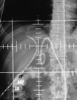
Although brachytherapy is commonly delivered through a transhepatic cholangiogram catheter,218 it has also been delivered using an endoscopic retrograde technique.215 To minimize the morbidity of sepsis, proper sterility is maintained and prophylactic antibiotics given. A size 12-French biliary drainage catheter is required to accommodate a 6-French HDR brachytherapy catheter. Therefore, the indwelling biliary drainage catheter is upsized to a size 12-French biliary drainage catheter, if required. Under fluoroscopy, the brachytherapy catheter is inserted into the biliary drainage catheter and advanced past the area of obstruction. A Tuohy-Borst (Y-shaped) adapter attached to the end of the biliary catheter allows concurrent external biliary drainage while holding the HDR catheter in place (Fig. 14-12). The area of the obstruction is irradiated along with 1 to 2 cm proximal and distal margins. It is important to leave the biliary drainage catheter in place after therapy to minimize biliary stricture.
Dose and Fractionation
The dose per fraction delivered is variable, but 5 Gy per fraction at a distance of 1 cm from the source is commonly used for three to four fractions (15 to 20 Gy total) to boost 45 Gy EBRT.216 If EBRT is not delivered, a palliative dose of 30 Gy in six fractions can be used.216 Concurrent chemotherapy (5-FU) is often added.
Clinical Results
An HDR dose escalation phase I/II study for patients with unresectable or partially resectable disease at the University of Miami used an HDR fraction size 7 Gy at 1 cm depth following external beam irradiation (45 Gy/standard fractionation).217 The treatment protocol increased the number of HDR fractions from 1 to 3 weekly (total external plus brachytherapy doses of 52 Gy, 59 Gy, 66 Gy, respectively). The corresponding median survivals of the three sequential dose groups were 9, 12.2, and 20.3 months, respectively. This did not reach statistical significance, but the complete or partial response rate was significantly improved statistically (25% for total dose of 52 Gy versus 80% for doses 59 and 66 Gy). One of 18 patients in this series experienced a grade III toxicity.
Cancer of the Head and Neck
Indications
Brachytherapy, especially using manually afterloaded iridium-192, has been widely used to treat head and neck cancers. HDR brachytherapy has been used in selected cases to reduce radiation exposure and permit optimization as summarized in Table 14-17.219–232 However, these advantages are offset by the need for multiple fractionation, since the critical structures of the head and neck area do not tolerate high doses per fraction. The nasopharynx is a site within the head and neck area that is easily accessed by an intracavitary HDR applicator.233–234 Leung et al. reported in 2008 their results from 145 patients with nasopharyngeal carcinoma treated with 66 Gy EBRT followed by two fractions of 10 to 12 Gy each via HDR.231 Five-year local failure–free survival was reported to be 95.8% with a 5-year major complication-free survival rate of 89.5%. Moreover, thin residual tumors (<10 mm) following EBRT and chemotherapy may be more suitable candidates.219 Additionally, recent results with the use of HDR brachytherapy in patients with recurrent and previously irradiated head neck tumors is promising.235–238
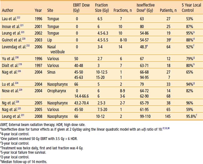
Dose and Fractionation
The use of HDR brachytherapy catheters incorporated in removable dental molds allows repeated fractionated outpatient brachytherapy in a highly reproducible manner without requiring repeated catheter insertion into the tumor.239 Suitable sites for mold therapy include the scalp, face, pinna, lip, buccal mucosa, maxillary antrum, hard palate, oral cavity, external auditory canal and the orbital cavity after exenteration. HDR can be used as the sole modality or in conjunction with EBRT. A total HDR dose equivalent to about 60 Gy LDR (prescribed at 0.5 cm depth) is recommended when used as the sole modality.227 Doses of approximately 15 to 20 Gy in three to five fractions can be delivered in this manner to boost 45 to 50 Gy EBRT. For nasopharyngeal tumors, doses of 18 Gy in six fractions are delivered by a special nasopharynx applicator to boost 46 to 60 Gy of EBRT.234
The use of HDR interstitial brachytherapy in the head and neck region in accessible sites (e.g., cheek, lip, tongue) as boost therapy following EBRT may be considered in lieu of LDR brachytherapy and may obviate the need for hospitalization. Typically, treatment schedules of 3 to 4 Gy per HDR fraction twice daily, six hours apart, for four to six fractions are used following 45 to 50 Gy EBRT.227
Another innovative approach is the use of intraoperative HDR brachytherapy. This permits normal tissues to be retracted or shielded during brachytherapy. Intraoperative HDR brachytherapy can access many sites in the head and neck area that are difficult to treat or are inaccessible by either LDR removable brachytherapy or electron beam intraoperative radiation therapy.240 The catheters are removed immediately after the single dose of radiation, hence minimizing inconvenience and permitting the use of brachytherapy in difficult-to-reach areas such as the base of the skull.240,241 Doses of 7.5 to 15.0 Gy are given if an external beam dose of 45 to 50 Gy is added. In recurrent tumors in which no further EBRT can be given, the single intraoperative dose is 15 to 20 Gy.225,226
Soft Tissue Sarcomas
Indications
The role of EBRT following wide local resection of soft tissue sarcoma is well established with excellent results. However, irradiation of large volumes of normal tissues has at times been associated with significant soft tissue fibrosis. To minimize morbidity, a few centers have used LDR brachytherapy, either alone 242 or with EBRT.243 A prospective randomized trial showed superior local control (80% at 5 years) in the group receiving brachytherapy versus 62% in the group not receiving brachytherapy.242 The major problem with LDR brachytherapy of large volumes is the radiation exposure involved. Hence, a few centers are investigating the use of HDR brachytherapy for soft tissue sarcomas.244–255 Pohar and colleagues recently reported a nonrandomized single institution comparison of LDR versus HDR before or following EBRT in 37 patients.255 Two-year local control was the same (94% with HDR and 90% with LDR) and there was a trend for reduced late severe complications with HDR (6% versus 30%). Of note, the median follow-up for the LDR group was 47 months, whereas the median follow-up for the HDR group was only 17 months.
Technique and Dose
HDR brachytherapy catheters are implanted along the tumor bed and radiopaque clips indicate the margins. A 2 to 5 cm margin proximally and distally is used after wide excision of tumor. Optimized treatment planning can be used to deliver a more homogeneous dose. Doses of 40 to 50 Gy are given in 12 to 15 fractions if the HDR is given alone.244,247 If EBRT (45 to 50 Gy) is added, the brachytherapy dose is limited to 18 to 25 Gy in four to seven fractions).256 Nerve tolerance to high dose per fraction is poor and HDR should be used with caution when catheters have to be placed in contact with neurovascular structures. The ABS suggests the following interventions to minimize morbidity in soft tissue sarcomas257:
Carcinoma of the Breast
Boost Therapy
Indication
A large randomized trial from the European Organization for Research and Treatment of Cancer (EORTC) has demonstrated the benefit of boost therapy in improving local control in patients with breast cancer with negative margins.258,259 The practical preference of most radiation oncologists to use electron beam as a boost technique must be balanced by its limitation in certain scenarios. Brachytherapy has been used to boost the EBRT dose in select high-risk patients260–262 but data are limited with the use of HDR as a boost262–265 (Table 14-18). Large breasts, deep-seated tumors, or both may hamper the use of electron beam. Moreover, positive or close margins or unknown margin status may indicate a greater risk of subclinical tumor burden and may require higher doses of radiation (Table 14-19). A more focused technique using breast brachytherapy as a boost technique may facilitate delivery of radiation as opposed to that delivered with EBRT.266
Table 14-18 Results of Breast-Conserving Therapy With Lumpectomy Plus High Dose Rate Brachytherapy or as a Boost to External Beam Radiation Therapy
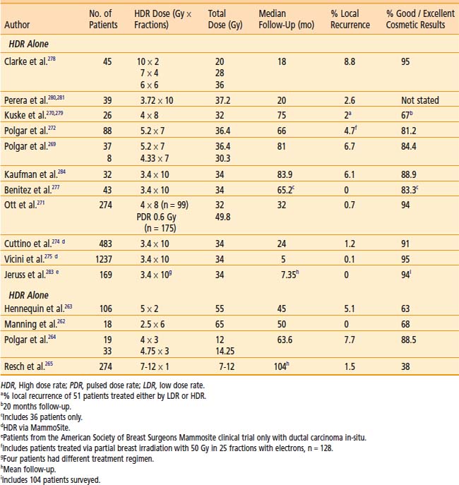
Table 14-19 Brachytherapy in the Conservative Management of Breast Cancer
| Indications for brachytherapy as the sole modality | Selection criteria for brachytherapy as the sole modality | Indications for brachytherapy as a boost to EBRT |
|---|---|---|
| 1. The patient lives a long distance from radiation oncology treatment facilities. | 1. All patients should be appropriate candidates for standard breast conservation therapy | 1. For patients with close, positive, or unknown margins |
| 2. The patient lacks transportation. | 2. Unifocal, invasive ductal carcinoma | 2. For patients with extensive intraductal component |
| 3. The patient is a professional whose schedule will not accommodate a 6-week course of therapy | 3. <3 cm in size | 3. For younger patients |
| 4. The patient is elderly, frail, or in poor health and therefore unable to travel for a prolonged course of daily treatment | 4. Negative microscopic surgical margins of excision | 4. For deep tumor location in a large breast |
| 5. The patient’s breasts are sufficiently large that they may have unacceptable toxicity with EBRT | 5. Axillary node negative by level I/II axillary dissection or sentinel node evaluation | 5. For CTV of irregular thickness |
EBRT, External beam radiation therapy; CTV, clinical target volume.
Polgar et al. reported the results of a randomized trial involving 207 women with stage I to II breast cancer treated with breast conserving surgery and whole breast radiotherapy and subsequently randomized to either no further therapy or radiation boost to the tumor bed.264 The radiation boost consisted of either 16 Gy of electron irradiation or 12 to 14.5 Gy fractionated HDR brachytherapy. Fifty-two patients were treated with HDR brachytherapy, and the 5-year local tumor control rate was 91.4%. Excellent to good cosmesis was reported in 88.5% of patients. Similar results were noted in the group of patients receiving an electron irradiation boost.
Technique
The success of breast brachytherapy is predicated by the need to precisely define the CTV (discussed earlier in this chapter). The ABS has published guidelines to assist in the accuracy of the treatment.267 A 2-cm margin around the lumpectomy cavity is recommended unless limited by the chest wall or skin. A practical way of defining the cavity is the intraoperative placement of clips at the periphery of the cavity to assist in the localization of the implanted volume and to guarantee adequacy of dosimetry coverage. A newer technique of cavity outlining using injection of biologically inert contrast in the cavity under ultrasound guidance as proposed by Kuske may also facilitate accurate placement of catheters when under real-time fluoroscopic or mammographic guidance.266 A minimum of two brachytherapy planes is required for most implants unless limited by the thinness of breast tissue (<2 cm). Assurance of correct spacing between needles (in the same plane) or planes of needles is necessary. The ABS recommends adequate treatment planning to assure dose homogeneity within the CTV and criteria to judge quality.
Dose
The optimal dose schedule for HDR boost therapy remains undefined. The brachytherapy boost can be given before or after EBRT, usually with a 1 to 2 week gap between EBRT and brachytherapy. The ABS recommends a dose equivalency of 10 to 20 Gy LDR following 45 to 50 Gy EBRT.267 Biomathematical models are often used to estimate equivalent HDR regimens.32,40 For example, an HDR regimen of five fractions of 310 cGy per fraction should approximate the early and late effects of 20 Gy LDR delivered at 0.5 Gy/h. Although biomathematical models can be used to estimate the appropriate dose, there is no standardized HDR fractionation schedule that can be recommended for the use of HDR as a boost. Controlled clinical studies are required to further define the most appropriate doses to be used for boost treatment.
Partial Breast Irradiation
Indications
Breast conservation therapy (BCT) has traditionally combined limited breast tissue resection and EBRT directed to the entire breast. Most breast recurrences are anatomically situated in close proximity to the lumpectomy site. The need for whole breast irradiation must be counterbalanced by the potential long-term risk of increased sequelae and the long treatment duration of EBRT. Recently there has been interest in using brachytherapy as the sole modality of treatment to decrease the 6-week treatment duration required for a course of EBRT to approximately 5 days.268–272 An abbreviated course of partial breast irradiation (PBI) would increase the logistical availability of BCT to more women and may achieve a more facile integration of chemotherapy. Careful selection of patients for PBI is critical to achieve success. Table 14-19 lists the patients in whom an accelerated (4- to 5-day) brachytherapy treatment course can be an attractive alternative to 6 weeks of EBRT.267 Patients with multicentric disease, inadequate excision, extensive intraductal component, and infiltrating lobular carcinoma are not recommended to have PBI.266
Technique
Depending on the selection criteria, final pathologic assessment is necessary to completely evaluate a patient for partial breast brachytherapy, and therefore the ABS does not advocate intraoperative treatment delivery at this time.273 The use of a single-channel MammoSite applicator (Hologic, Inc., Bedford, MA) has simplified the brachytherapy procedure.270 Cuttino et al. reported a good to excellent cosmetic result of 91%, with median follow-up of 24 months, in 483 patients treated with the MammoSite applicator.274 In addition, a multi-institutional registry trial performed by the American Society of Breast Surgeons to evaluate the clinical use of the MammoSite applicator recently reported an early first analysis of a good to excellent cosmetic result of 95% (1030 of 1084 patients) and one local recurrence at a median follow-up of 5 months in 1237 patients.275
Dose and Fractionation
The ABS recommends a total dose of 34 Gy in 10 fractions to the CTV when HDR brachytherapy is used as the sole modality.267 The HDR treatments of 3.4 Gy are generally given at two fractions per day separated by at least 6 hours. This was also the dose used in a Phase II RTOG trial276 and is the dose used in the currently open Phase III National Surgical Adjuvant Breast and Bowel Project (NSABP) B-39 Trial.
Clinical Results
The results of HDR brachytherapy as the sole modality are included in Table 14-18.269–272,274,275,277–284 Based on promising results from earlier Phase II data, the RTOG in conjunction with the NSABP opened a phase III randomized study (NSABP B-39) in March 2005 investigating standard whole breast radiotherapy versus partial breast radiotherapy after lumpectomy for women with early stage breast cancer. The partial breast treatment arm consists of three therapeutic options: intensity-modulated radiation therapy (IMRT), HDR brachytherapy via MammoSite, and HDR brachytherapy via a multicatheter interstitial implant. The required dose for the brachytherapy treatment is 34 Gy given in 10 fractions over 5 days. Target accrual is 4300 patients over approximately 43 months; it is hoped that over time the data will shed some light on the usefulness of partial breast irradiation and brachytherapy as a sole modality of treatment. Further clinical studies are required to further define the most appropriate candidates for breast brachytherapy as a sole modality treatment and to determine the best delivery method of brachytherapy (multicatheter interstitial implant versus balloon brachytherapy) in such patients.
Neoadjuvant Breast Radiation
Use of interstitial HDR brachytherapy as neoadjuvant treatment in select patients not amenable to breast-conserving surgery at presentation has recently been reported by Roddiger et al.285 Fifty-three patients who were unable to undergo breast conserving surgery either because of initial tumor size or an unfavorable breast-tumor ratio were treated with systemic chemotherapy and HDR brachytherapy with 5 Gy twice per day for 3 days (total dose 30 Gy). In this study, 56.6% of patients went on to receive breast conserving surgery and the local recurrence rate was 2% with a median follow-up of 56 months. Further studies are needed to fully define the role of interstitial HDR brachytherapy as neoadjuvant treatment, but these results are encouraging.
Carcinoma of the Skin
Little interest has developed regarding the use of brachytherapy for skin cancers. Most basal cell and squamous cell carcinomas addressed radiotherapeutically are treated with electron beam. Electron beam presents certain constraints, however. These include an initial decrement of dose at the skin surface (necessitating bolus equivalent material), greater bone dose absorption underneath skin (than soft tissue) and dose decrement at the periphery of the field in highly sloped surfaces. Since most skin cancers are superficial (<3 mm), 6 MeV electrons are typically used. A comparison of dose distribution of 6 MeV electrons (with 0.5-cm bolus) compared to the Freiburg applicator (Nucletron Corp., Veenendaal, The Netherlands) (for HDR) for treatment of a skin cancer of the hand is presented in tabular form (Table 14-20). Dose distributions in Table 14-20 indicate a superior dose profile for HDR (compared to electron beam) with less dose delivered to the subcutaneous tissues and deeper tissues (e.g., bone, joints, tendons, lacrimal gland). The Freiburg applicator, which is typically used for intraoperative HDR brachytherapy,286–288 offers certain practical advances in the use of brachytherapy: (1) malleability and ease of adaptability to various skin contours including sloped surfaces, (2) variability of sizes, (3) no need for bolus. The disadvantage of the Freiburg HDR applications is the labor intensiveness, with a typical time of 1 to 2 hours for treatment setup verification on the simulator, and repeat dosimetry if necessary. These disadvantages may be balanced by the fewer number of treatment fractions used in view of the enhanced dose distribution.
Table 14-20 Comparison of Electrons and High Dose Rate (HDR) Freiburg Flap Application DRB for the Treatment of Skin Cancer
| Depth, cm | 6 MeV Electron (0.5 cm Bolus), % Dose | HDR Normalized at 0.2 cm Depth, % Dose |
|---|---|---|
| 0.0 | 88 | 105-110 |
| 0.5 | 98 | 85 |
| 1.0 | 98 | 65 |
| 1.5 | 78 | 55 |
| 2.0 | 36 | 30 |
Pediatric Tumors
LDR brachytherapy has been used in children to reduce the deleterious effects of EBRT.289–292 However, LDR brachytherapy is difficult to perform in young children and infants, because they require prolonged sedation and immobilization with close monitoring, which increases the risk of radiation exposure to nursing staff and parents. HDR is therefore very appealing in infants and younger children and has undergone various trials.293–297 The recommended dose for HDR as monotherapy is 36 Gy in 12 fractions given at 3 Gy per fraction (prescribed at 0.5 cm) twice a day.257,296–297 The interval between fractions is at least 6 hours. There are no published data giving any dose recommendations for HDR as a boost to EBRT. The L-Q model40 can be used to calculate a fractionation scheme equivalent to that of an LDR implant boost-dose of 15 to 25 Gy (prescribed at 0.5 cm). The recommended dose for intraoperative HDR brachytherapy as a boost to EBRT is 10 to 15 Gy (prescribed at 0.5 cm), depending on the extent of residual disease.298–302 According to the Intergroup Rhabdomyosarcoma Study (IRS) the standard EBRT dose for pediatric soft tissue sarcomas is 40 Gy for microscopic disease and 50 Gy for gross disease. IOHDR allows reduction in the dose of EBRT to 27 to 30 Gy so that concerns for impaired growth and organ function is greatly reduced.296,302,303
The results of HDR brachytherapy in the treatment of pediatric tumors are summarized in Table 14-21.295,302,304–308 Although the long-term morbidity of HDR brachytherapy in young children is not fully known, one may expect preservation of organ functions similar to the that seen with LDR brachytherapy.289 Because of the complexities involved in pediatric HDR brachytherapy, it is recommended that the use of HDR brachytherapy in pediatric tumors be limited to centers that have experience with pediatric implants.257
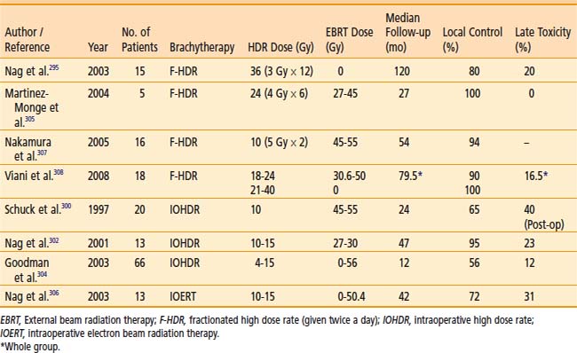
Intraoperative High Dose Rate Brachytherapy
Indications
Maximum surgical debulking allows the residual micro- or macroscopic component to be amenable to intraoperative and perioperative brachytherapy techniques.302,309,310 Intraoperative high dose rate brachytherapy (IOHDR) is an extreme example of reduced fractionation in that only a single HDR brachytherapy dose is applied.287,310–313 This results in an inherent radiobiological disadvantage, since the advantages of fractionation (repair of normal tissue damage, reoxygenation of hypoxic tumor cells, and movement of tumor cells from the radioresistant S-phase to the more radiosensitive mitotic phase of the cell cycle) are lost. L-Q model calculations show that there has to be a dose reduction of 20% to 25% to the late reacting normal tissues for isoeffect. However, the dose reduction achieved by 1- to 4-cm displacement of normal tissue is probably much more (closer to 60% to 90% reduction).310 Hence, HDR in these situations can be advantageous. However, if such a dose reduction cannot be achieved in normal tissues, HDR brachytherapy becomes disadvantageous. Intraoperative HDR brachytherapy has much promise because normal tissues can be displaced or partially shielded during the irradiation. Unfortunately, because of the limited availability of a shielded operating room, only a few centers have reported using intraoperative HDR brachytherapy.287,298,301,311–315 Intraoperative HDR brachytherapy may have certain technical advantages over intraoperative electron beam therapy, particularly in steeply sloped surfaces, narrow cavity spaces, and in certain highly angulated directions inaccessible to the electron beam.
Technique
The surgery is performed in a shielded operating room with remote anesthesia and a video monitoring system. Maximal surgical debulking is attempted whenever possible. The tumor bed is irradiated using special intraoperative applicators incorporated with HDR catheters, parallel and 1 cm apart. The use of a fixed-geometry applicator with an array of 1-cm–spaced catheters allows the patient to be treated without delay using preplanned dosimetry for the selected applicator. Normal tissues are either retracted away from the high-dose area or shielded. Doses of 10 to 20 Gy are usually given as a single fraction over 10 to 60 minutes.313 A 2 to 4 cm displacement of tissue typically results in an 80% to 93% dose reduction, whereas 1 to 5 mm of lead shielding reduces the normal tissue dose by 20% to 80%, respectively.310
Reduction of Brachytherapy Errors
Meticulous quality assurance and trained personnel are key to reducing errors during HDR brachytherapy. The International Commission on Radiological Protection (ICRP) recommendations for quality assurance procedures necessary to reduce errors and prevent accidents in HDR brachytherapy programs are summarized in Table 14-22.316 The general recommendations include establishing a written comprehensive quality assurance program, formation of a hospital radiation safety committee, external auditing of procedures, peer reviewing of each case, and reporting of every incident or accident. The specific recommendations cover a broad range of topics. Training in HDR brachytherapy should commence prior to acquisition of machines, should follow a team approach, and should be sequential in the introduction of techniques with simpler techniques first followed by more complex treatments. For example, multiple-plane flexible implants should not be attempted first. Transport regulations of sources should be adhered to and performed by a factory–trained and certified operator. In addition, new sources should be measured in a calibrated well chamber to verify reported activity, at which time it is advisable to do a full commissioning including physics and mechanical quality assurance checks. It is recommended that all systems of delivery (i.e., catheters) be closed-ended, that the step size at a particular center be constant (e.g., 5 mm) for all treatments, and that a dedicated self-contained brachytherapy suite exist to house all equipment.
Table 14-22 International Commission on Radiological Protection Recommendation for Prevention of HDR Brachytherapy Accidents
QA, Quality assurance; HDR, high dose rate.
HDR Brachytherapy in Developing Countries
HDR brachytherapy has special relevance for developing countries where resources may be scarce. In this regard, the International Atomic Energy Agency (IAEA) has issued recommendations for the use of HDR brachytherapy in the developing countries.317 A brief summary is given here; however, readers interested in the details are referred to the original article.
Summary
It is expected that the use of HDR brachytherapy will greatly expand over the next decade and that refinements will occur primarily in the integration of imaging (CT, MRI, intraoperative ultrasonography), and optimization of dose distribution.49,318 It is anticipated that better tumor localization and normal tissue definition will help to optimize dose distribution to the tumor and reduce normal tissue exposure. The development of well controlled randomized trials addressing issues of efficacy, toxicity, quality of life, and costs versus benefits will ultimately define the role of HDR brachytherapy in the therapeutic armamentarium.
1 Report No. 38, Dose and volume specification for reporting intracavitary brachytherapy for gynecology; 1985; International Commission on Radiation Units and Measurements, Bethesda, MD.
2 Nag S, Samsami N. Pitfalls of inappropriate optimization. J Brachyther Int. 2000;16:187-198.
3 Kurhanewicz J, Vigneron B, Nelson S. Three-dimensional magnetic resonance spectroscopic imaging of brain and prostate cancer. Neoplasia. 2000;2:166.
4 Lahanas M, Baltas D, Zambouglou N. Anatomy-based three-dimensional dose optimization in brachytherapy using multiple objective genetic algorithm. Med Phys. 1999;26:9.
5 Lessard E, Pouliot J. Anatomy-based dose optimization for HDR-brachytherapy of the prostate using fast simulated annealing algorithm. Med Phys. 2001;28:773.
6 Pouliot J, Tremblay D, Roy J, Filice S. Optimization of permanent 125I prostate implants using fast simulated annealing. Int J Radiat Oncol Biol Phys. 1996;36:711.
7 Kneschaurek P, Schiessl W, Wehrmann R. Volume-based dose optimization in brachytherapy. Int J Radiat Oncol Biol Phys. 1999;45:811.
8 Hsu I-C, Lessard E, Weinberg V, et al: Comparison of inverse planning and geometrical optimization for prostate high dose rate brachytherapy. Presented at the 23rd American Brachytherapy Society Meeting, Orlando, Fla. May 24, 2002.
9 Pouliot J, Charra-Brunaud C, Kim YB, et al: Inverse planning for HDR brachytherapy: Clinical implementation. Presented at the 23rd American Brachytherapy Society Meeting, Orlando, Fla. May 24, 2002.
10 Kirkpatrick S, Gelatt CD, Vecchi PM. Optimization by simulated annealing. Science. 1983;220:671.
11 Pouliot J, Taschereau R, Coté C, et al. Dosimetric aspects of permanent radioactive implants for the treatment of prostate. Phys Canada. 1999;55:61.
12 Lachance B, B-Nadeau D, Lessard E, et al. Early clinical experience with anatomy-based inverse planning dose optimization for HDR boost of the prostate. Int J Radiat Oncol Biol Phys. 2002;54:1.
13 Lessard E, Hsu I-C, Pouliot J. Inverse planning for interstitial gynecological template brachytherapy: truly anatomy based planning. Int J Radiat Oncol Biol Phys. 2002;54:5.
14 Fisch BM, Pickett B, Weinberg V, et al. Dose of radiation received by the bulb of the penis correlates with risk of impotence after three-dimensional conformal radiotherapy for prostate cancer. J Urology. 57, 2001.
15 Lessard E, Hsu I-C, Fish B, et al. Inverse planning ability to protect the bulb of the penis and other organs at risk in HDR-brachytherapy of the prostate. Med Phys. 2002;29:6.
16 Kubicky C, Yeh B, Lessard E, et al. Inverse planning simulated annealing for magnetic resonance imaging-based intracavitary high-dose-rate brachytherapy for cervical cancer. Brachytherapy. 2008;7:242-247.
17 Citrin D, Ning H, Guion P, et al. Inverse treatment planning based on MRI for HDR prostate brachytherapy. Int J Radiat Oncol Biol Phys. 2005;61:1267-1275.
18 Pouliot J, Kim Y, Lessard E, et al. Inverse planning for HDR prostate brachytherapy use to boost dominant intra-prostatic lesion defined by magnetic-resonance spectroscopy imaging. Int J Radiat Oncol Biol Phys. 2004;59:1196-1207.
19 DeWitt KD, Hsu I-C, Weinberg VK, et al. 3-D inverse treatment planning for the tandem and ovoid applicator in cervical cancer. Int J Radiat Oncol Biol Phys. 2005;63:1270-1274.
20 Ménard C, Susil R, Choyke P, et al. MRI-guided HDR prostate brachytherapy in a standard 1.5T scanner. Int J Radiat Oncol Biol Phys. 2004;59:1414-1423.
21 Morton G, Sankreacha R, Halina P, et al. A comparison of anatomy-based inverse planning with simulated annealing and graphical optimization for high-dose-rate prostate brachytherapy. Brachytherapy. 2008;7:12-16.
22 Mamoudieh A, Tremblay C, Beaulieu L, et al. Anatomy-based inverse planning dose optimization in HDR prostate implant: a toxicity study. Radiother Oncol. 2005;75:318-324.
23 Jacob D, Raben A, Sarkar A, et al. Anatomy-based inverse planning simulated annealing optimization in high-dose-rate prostate brachytherapy: significant dosimetric advantage over other optimization techniques. Int J Radiat Oncol Biol Phys. 2008;72(3):820-827.
24 Hall EJ. Radiobiology for the radiologist, ed 5. Philadelphia: Lippinott Williams & Wilkins; 2000. p 401
25 Brenner DJ, Hall EJ. Conditions for the equivalence of continuous to pulsed low dose rate brachytherapy. Int J Radiat Oncol Biol Phys. 1991;20:181.
26 Brenner DJ, Hall EJ. Fractionated high dose rate versus low dose rate regimens for intracavitary brachytherapy of the cervix. Br J Radiol. 1991;64:133.
27 Dale RG. The application of the linear-quadratic dose-effect equation to fractionated and protracted radiotherapy. Br J Radiol. 1985;58:515.
28 Fowler JF. Why shorter half-times for repair lead to greater damage in pulsed brachytherapy. Int J Radiat Oncol Biol Phys. 1993;26:353.
29 Thames HD. Effect-independent measurements of tissue responses to fractionated irradiation. Int J Radiat Biol Phys. 1984;45:1.
30 Orton CG. High and low dose rate remote afterloading: a critical comparison. In: Sauer R, editor. International radiation therapy techniques—brachytherapy. Berlin: Springer-Verlag; 1991:53.
31 Hall EJ. Radiobiology for the Radiologist, ed 5. Philadelphia: Lippincott Williams & Wilkins; 2000. p 74
32 Barendsen GW. Dose fractionation, dose rate and iso-effect relationships for normal tissue responses. Int J Radiat Oncol Biol Phys. 1982;8:1981.
33 Orton CG. Recent developments in time-dose modelling. Australas Phys Eng Sci Med. 1991;14:57.
34 Dale RG. What minimum number of fractions is required with high dose-rate remote afterloading? Br J Radiol. 1987;60:301.
35 Dale RG. The use of small fraction numbers in high dose-rate gynecological afterloading: Some radiobiological considerations. Br J Radiol. 1990;63:290.
36 Stitt J, Fowler J, Thomadsen B, et al. High dose rate intracavitary brachytherapy for carcinoma of the cervix: The Madison system:1. Clinical and radiobiological considerations. Int J Radiat Oncol Biol Phys. 1992;24:335.
37 Bentzen SM, Saunders MI, Dische S. Repair half-times estimated from the observations of treatment-related morbidity after CHART or conventional radiotherapy in head and neck cancer. Radiotherapy Oncol. 1999;53:219.
38 Orton CG. High-dose-rate brachytherapy may be radiobiologically superior to low dose rate due to slow repair of late-responding normal tissue cells. Int J Radiat Oncol Biol Phys. 2001;49:183.
39 Orton CG, Seyedsadr M, Somnay A. Comparison of high and low dose rate remote afterloading for cervix cancer and the importance of fractionation. Int J Radiat Oncol Biol Phys. 1991;21:1425.
40 Nag S, Gupta N. A simple method of obtaining equivalent doses for use in HDR brachytherapy. Int J Radiat Oncol Biol Phys. 2000;46:507-513.
41 Dusenbery K, Carson L, Potish R. Perioperative morbidity and mortality of gynecologic brachytherapy. Cancer. 1991;67:2786.
42 Abitbol A, Stitt J, Schwade J, Lewin A. High dose rate brachytherapy for carcinoma of the cervix. In: Nag S, editor. High dose rate brachytherapy: a textbook. Armonk, NY: Futura Publishing; 1994:373.
43 Sharma V, Mahantshetty U, Menon V, et al. A modified technique for high-dose-rate intracavitary brachytherapy in advanced cancer of the cervix. Brachytherapy. 2003;2:246-248.
44 Nag S, Chao C, Erickson B, et al. The American Brachytherapy Society recommendations for low-dose-rate brachytherapy for carcinoma of the cervix. Int J Radiat Oncol Biol Phys. 2002;52:33-48.
45 Nag S, Orton C, Petereit DG, et al. The American Brachytherapy Society recommendations for HDR brachytherapy of the cervix. Int J Radiat Oncol Biol Phys. 2000;48:201-211.
46 Hricak H, Yu K. Radiology in invasive cervical cancer. AJR AM J Roentgenol. 1996;167:1101-1108.
47 Kim SH, Choi BI, Lee HP, et al. Uterine cervical carcinoma: comparison of CT and MRI findings. Radiology. 1990;175:45-51.
48 Subak L, Hricak H, Powell B, et al. Cervical carcinoma: computed tomography and magnetic resonance imaging for operative staging. Obstet Gynecol. 1995;86:43-50.
49 Haie-Meder C, Potter R, Van Limbergen E, et al. Recommendations from Gynaecological (GYN) GEC-ESTRO Working Group (I): concepts and terms in 3D image based 3D treatment planning in cervix cancer brachytherapy with emphasis on MRI assessment of GTV and CTV. Radiother Oncol. 2005;74:235-245.
50 Potter R, Haie-Meder C, Van Limbergen E, et al. Recommendations from gynaecological GEC ESTRO working group (II): concepts and terms in 3D image-based treatment planning in cervix cancer brachytherapy—3D dose volume parameters and aspects of 3D image-based anatomy, radiation physics, radiobiology. Radiother Oncol. 2006;78:67-77.
51 Poetter R, Dimopoulos J, Kirisits C, et al. Vienna experience in 145 cervical cancer patients treated by systemic MRI-based intracavitary + interstitial brachytherapy from 1998–2003: Impact on local control. Brachytherapy. 2006;5(2):86-87.
52 Ferrigno R, Nishimoto IN, dos Santos Novaes PER, et al. Comparison of low and high dose rate brachytherapy in the treatment of uterine cervix cancer. Retrospective analysis of two sequential series. Int J Radiat Oncol Biol Phys. 2005;62:1108-1116.
53 Patel FD, Rai B, Mallick I, et al. High-dose-rate brachytherapy in uterine cervical carcinoma. Int J Radiat Oncol Biol Phys. 2005;62:125-130.
54 Souhami L, Corns R, Duclos M, et al. Long-term results of high dose rate brachytherapy in cervix cancer using a small number of fractions. Gynecol Oncol. 2005;97:508-513.
55 Abitbol A, Wolfson A, Lewin A, et al. Management of stage I-B,II-A, and II-B carcinoma of the cervix: Results of an institutional clinical trial. Am J Clin Oncol. 1996;19:223.
56 Nag S, Young D, Orton C, Int J Radiat Oncol Biol Phys. Surveyof the brachytherapy practice for carcinoma of the cervix: A report of the Clinical Research Committee of the American Brachytherapy Society. Gynecol Oncol. 1999;73:111-118.
57 Joslin CA. The Cathetron as part of the radical management of cervix cancer. Br J Radiol. 1980;17(Suppl 17):11-16.
58 Rotte K. A randomized clinical trial comparing a high dose-rate with a conventional dose-rate afterloading machine (the Cathetron). Int J Radiat Oncol Biol Phys. 1983;9:931.
59 Arai T, Morita S, Kutsutani Y, et al. Relationships between total iso-effect dose and number of fractions for the treatment of uterine cervical carcinoma by high dose-rate intracavitary irradiation. Br J Radiol. 1980;17:89.
60 Sato S, Yajima A, Suzuki M. Therapeutic results using high-dose-rate intracavitary irradiation in cases of cervical cancer. Gynecol Oncol. 1984;19:143.
61 Arai T, Nakano T, Morita S, et al. High-dose-rate remote afterloading intracavitary radiation therapy for cancer of the uterine cervix: a 20-year experience. Cancer. 1992;69:175.
62 Akine Y, Arimoto H, Ogino T, et al. High-dose-rate intracavitary irradiation in the treatment of carcinoma of the uterine cervix: early experience with 84 patients. Int J Radiat Oncol Biol Phys. 1988;14:893.
63 Chen M-S, Lin F-J, Hong C-H, et al. High-dose-rate afterloading technique in the radiation treatment of uterine cervical cancer: 399 cases and 9 years experience in Taiwan. Int J Radiat Oncol Biol Phys. 1991;20:915.
64 Ferrigno R, Nishimoto IN, dos Santos Novaes PER, et al. Comparison of low and high dose rate brachytherapy in the treatment of uterine cervix cancer. Retrospective analysis of two sequential series. Int J Radiat Oncol Biol Phys. 2005;62:1108-1116.
65 Lorvidhaya V, Tonusin A, Changwiwit W, et al. High-dose-rate afterloading brachytherapy in carcinoma of the cervix: and experience of 1992 patients. Int J Radiat Oncol Biol Phys. 2000;46:1185-1191.
66 Patel FD, Rai B, Mallick I, et al. High-dose-rate brachytherapy in uterine cervical carcinoma. Int J Radiat Oncol Biol Phys. 2005;62:125-130.
67 Petereit DG, Sarkaria JN, Potter DM, et al. High-dose-rate versus low-dose-rate brachytherapy in the treatment of cervical cancer: analysis of tumor recurrence—the University of Wisconsin experience. Int J Radiat Oncol Biol Phys. 1999;45:1267-1274.
68 Potter R, Knocke TH, Fellner C, et al. Definitive radiotherapy based on HDR brachytherapy with iridium 192 in uterine cervix carcinoma: report of the Vienna University Hospital findings (1993–1997) compared to the preceding period in the context of ICRU 38 recommendations. Cancer Radiother. 2000;4:159-172.
69 Sood BM, Gorla G, Gupta S, et al. Two fractions of high-dose-rate brachytherapy in the management of cervix cancer: clinical experience with and without chemotherapy. Int J Radiat Oncol Biol Phys. 2002;53:702-706.
70 Souhami L, Corns R, Duclos M, et al. Long-term results of high dose rate brachytherapy in cervix cancer using a small number of fractions. Gynecol Oncol. 2005;97:508-513.
71 Toita T, Kakinohana Y, Ogawa K, et al. Combination external beam radiotherapy and high-dose-rate intracavitary brachytherapy for uterine cervical cancer: analysis of doses and fractionation schedule. Int J Radiat Oncol Biol Phys. 2003;56:1344-1353.
72 Falkenberg E, Kim RY, Meleth S, et al. Low-dose-rate vs. high-dose-rate intracavitary brachytherapy for carcinoma of the cervix: the University of Alabama at Birmingham (UAB) experience. Brachytherapy. 2006;5:49-55.
73 Orton CG. High dose rate versus low dose rate brachytherapy for gynecological cancer. Semin Radiat Oncol. 1993;3:232.
74 Orton CG, Seyedsadr M, Somnay A. Comparison of high and low dose rate remote afterloading for cervix cancer and the importance of fractionation. Int J Radiat Oncol Biol Phys. 1991;21:1425.
75 Fu K, Phillips T. High-dose-rate versus low-dose-rate intracavitary brachytherapy for carcinoma of the cervix. Int J Radiat Oncol Biol Phys. 1990;19:791-796.
76 Petereit D, Peracey R. Literature analysis of high dose rate brachytherapy fractionation schedules in the treatment of cervical cancer: Is there an optimal fractionation schedule? Int J Radiat Oncol Biol Phys. 1999;43:359-366.
77 Shigematsu Y, Nishiyama K, Masaki N, et al. Treatment of carcinoma of the uterine cervix y remotely controlled afterloading intracavitary radiotherapy with high-dose rate: a comparative study with a low-dose rate system. Int J Radiat Oncol Biol Phys. 1983;9:351-356.
78 Patel FD, Sharma SC, Pritam SN, et al. Low dose rate versus high dose rate brachytherapy in the treatment of carcinoma of the uterine cervix: a clinical trial. Int J Radiat Oncol Biol Phys. 1994;28:335-341.
79 Hareyama M, Sakata K, Oouchi A, et al. High-dose rate and low-dose rate intracavitary therapy for carcinoma of the uterine cervix: a randomized trial. Cancer. 2002;94:117-124.
80 Lertsanguansinchai P, Lertbutsayanukul C, Shotelersuk K, et al. Phase III randomized trial comparing LDR and HDR brachytherapy in treatment of cervical carcinoma. Int J Radiat Oncol Biol Phys. 2004;59:1424-1431.
81 Hricak H, Yu K. Radiology in invasive cervical cancer. AJR Am J Roentgenol. 1996;167:1101-1108.
82 Kim SH, Choi BI, Lee HP, et al. Uterine cervical carcinoma: comparison of CT and MRI findings. Radiology. 1990;175:45-51.
83 Subak L, Hricak H, Powell B, et al. Cervical carcinoma: computed tomography and magnetic resonance imaging for pre-operative staging. Obstet Gynecol. 1995;86:43-50.
84 Viswanathan AN, Dimopoulos J, Kirisits C, et al. Computed tomography versus magnetic resonance imaging-based contouring in cervical cancer brachytherapy: Results of a prospective trial and preliminary guidelines for standardized contours. Int J Radiat Oncol Biol Phys. 2007;68:491-498.
85 Lindegaard JC, Tanderup K, Nielsen SK, et al. MRI-guided 3D optimization significantly improves DVH parameters of pulsed-dose-rate brachytherapy in locally advanced cervical carcinoma. Int J Radiat Oncol Biol Phys. 2008;71:756-764.
86 De Brabandere M, Mousa AG, Nulens A, et al. Potential of dose optimization in MRI-based PDR brachytherapy of cervix carcinoma. Radiother Oncol. 2008;88(2):217-226.
87 Chajon E, Dumas I, Touleimat M, et al. Inverse planning approach 3-D MRI-based pulse-dose rate intracavitary brachytherapy in cervix cancer. Int J Radiat Oncol Biol Phys. 2007;69:955-961.
88 Potter R, Dimopoulos J, Georg P, et al. Clinical impact of MRI assisted dose volume adaptation and dose escalation in brachytherapy of locally advanced cervix cancer. Radiother Oncol. 2007;83:148-155.
89 Creutzberg CL, Van Putten WLJ, Koper PCM, et al. Surgery and postoperative radiotherapy versus surgery alone for patients with stage-1 endometrial carcinoma: multicentre randomised trial. Lancet. 2000;355:1404-1411.
90 Scholten AN, van Putten WLJ, Beerman H, et al. Postoperative radiotherapy for stage I endometrial carcinoma: long-term outcome of the randomized PORTEC trial with central pathology review. Int J Radiat Oncol Biol Phys. 2005;63:834-838.
91 Keys HM, Roberts JA, Brunetto VL, et al. A phase III trial of surgery with or without adjunctive external pelvic radiation therapy in intermediate risk endometrial adenocarcinoma: a Gynecologic Oncology Group study. Gynecol Oncol. 2004;92:744-751.
92 Nout RA, Putter H, Jurgenliemk-Schulz IM, et al. Vaginal brachytherapy versus external beam pelvic radiotherapy for high-intermediate risk endometrial cancer: Results of the randomized PORTEC-2 trial. J Clin Oncol. 26, 2008. Abstract LBA5503
93 Mandell LM, Nori D, Anderson LL, Hilaris BS. Postoperative vaginal radiation in endometrial cancer using a remote afterloading technique. Int J Radiat Oncol Biol Phys. 1985;11:473.
94 Stitt JA. High-dose-rate intracavitary brachytherapy for gynecologic malignancies. Oncology. 1992;6:59.
95 Rotte K. Technique and results of HDR afterloading in cancer of the endometrium. In: Martinez AA, Orton CG, Mould RF, editors. Brachytherapy HDR and LDR. Columbia, Md: Nucletron; 1990:68.
96 Peschel RE, Healey G, Smith RJ. High dose rate remote afterloading for endometrial cancer. Endo Hyper Oncol. 1989;5:209.
97 Lybert MLM, van Putten WLJ, Ribot JG, et al. Endometrial carcinoma: High dose rate brachytherapy in combination with external irradiation—a multivariate analysis of relapses. Radiother Oncol. 1989;16:245.
98 Sorbe BG, Smeds AC. Postoperative vaginal irradiation with high dose rate afterloading technique in endometrial carcinoma stage I. Int J Radiat Oncol Biol Phys. 1990;18:305.
99 Alektiar KM, McKee A, Venkatraman E, et al. Intravaginal high-dose-rate brachytherapy for stage IB (FIGO grade 1,2) endometrial cancer. Int J Radiat Oncol Biol Phys. 2002;53:707-713.
100 Alektiar KM, Venkatraman E, Chi DS, et al. Intravaginal brachytherapy alone for intermediate-risk endometrial cancer. Int J Radiat Oncol Biol Phys. 2005;62:111-117.
101 Anderson JM, Stea B, Hallum AV, et al. High-dose-rate postoperative vaginal cuff irradiation alone for stage IB and IC endometrial cancer. Int J Radiat Oncol Biol Phys. 2000;46:417-425.
102 Chadha M, Nanavati PJ, Liu P, et al. Patterns of failure in endometrial carcinoma stage IB grade 3 and IC patients treated with postoperative vaginal vault brachytherapy. Gynecol Oncol. 1999;75:103-107.
103 Nag S, Erickson B, Parikh S, et al. The American Brachytherapy Society recommendations for HDR brachytherapy for carcinoma of the endometrium. Int J Radiat Oncol Biol Phys. 2000;48:779-790.
104 Petereit DG, Tannehill SP, Grosen EA, et al. Outpatient vaginal cuff brachytherapy for endometrial cancer. Int J Gynecol Cancer. 1999;9:456-462.
105 Rittenberg PVC, Lotocki RJ, Heywood MS, et al. High-risk surgical stage I endometrial cancer: outcomes with vault brachytherapy alone. Gynecol Oncol. 2003;89:288-294.
106 Weiss E, Hirnle P, Arnold-Bofinger H, et al. Adjuvant vaginal high-dose-rate afterloading alone in endometrial carcinoma: patterns of relapse and side effects following low-dose therapy. Gynecol Oncol. 1998;71:72-76.
107 Horowitz NS, Peters WA, Smith MR, et al. Adjuvant high dose rate vaginal brachytherapy as treatment of stage I and II endometrial carcinoma. Obstet Gynecol. 2002;99:235-240.
108 Macleod C, Fowler A, Duval P, et al. Adjuvant high-dose-rate brachytherapy with or without external beam radiotherapy post-hysterectomy for endometrial cancer. Int J Gynecol Cancer. 1999;9:247-255.
109 Rippa P, Seppo K, Kauppila MD. Comparison of Heyman packing and Cathetron afterloading methods in the treatment of endometrial cancer. Br J Radiol. 1985;58:437-441.
110 Chong I, Hoskin PJ. Vaginal vault brachytherapy as sole postoperative treatment for low-risk endometrial cancer. Brachytherapy. 2008;7:195-199.
111 Jolly S, Vargas C, Kumar T, et al. Vaginal brachytherapy alone: an alternative to adjuvant whole pelvis radiation for early stage endometrial cancer. Gynecol Oncol. 2005;97:887-892.
112 Solhjem MC, Petersen IV, Haddock MG. Vaginal brachytherapy alone is sufficient adjuvant treatment of surgical stage I endometrial cancer. Int J Radiat Oncol Biol Phys. 2005;62:1379-1384.
113 Sorbe B, Straumits A, Karlsson L. Intravaginal high-dose-rate brachytherapy for stage I endometrial cancer: a randomized study of two dose-per-fraction levels. Int J Radiat Oncol Biol Phys. 2005;62:1385-1389.
114 Pearcey RG, Petereit DG. Post-operative high dose rate brachytherapy in patients with low to intermediate risk endometrial cancer. Radiother Oncol. 2000;56:17-22.
115 Stitt JA. Dose specification for inoperable endometrial carcinoma: the Madison system. Activity/Int Selectron Brachyther J. 1991;5:32.
116 Knocke TH, Kucera H, Weidinger B, et al. Primary treatment of endometrial carcinoma with high-dose-rate brachytherapy: results of 12 years of experience with 280 patients. Int J Radiat Oncol Biol Phys. 1997;37:359-365.
117 Kucera H, Knocke TH, Potter R. Treatment of endometrial carcinoma with high-dose-rate brachytherapy alone in medically inoperable stage I patients. Acta Obstet Gynecol Scand. 1998;77:1008-1012.
118 Kucera H, Weghaupt K. Treatment of inoperable endometrial carcinoma with intracavitary high dose rate iridium irradiation. Strahlenther Onkol. 1986;9:508.
119 Nag S. Modern techniques of radiation therapy for endometrial cancer. Clin Obstet Gynecol. 1996;39:728-744.
120 Nguyen T, Petereit DG. High-dose-rate brachytherapy for medically inoperable stage I endometrial cancer. Gynecol Oncol. 1998;71:196-203.
121 Niazi TM, Souhami L, Portelance L, et al. Long-term results of high-dose-rate brachytherapy in the primary treatment of medically inoperable stage I-II endometrial carcinoma. Int J Radiat Oncol Biol Phys. 2005;63:1108-1113.
122 Taina E. High versus low dose rate intracavitary radiotherapy in the treatment of carcinoma of the uterus. Acta Obstet Gynecol Scand. 1981;103:1.
123 Snelling MD, Hambert HE. The treatment of carcinoma of the cervix and endometrium using the Cathetron at the Middlesex Hospital. Clin Radiol. 1979;30:253.
124 Sipila P, Kauppila A. Intracavitary irradiation of endometrial carcinoma using a high intensity Co-60 afterloading method. Acta Oncol. 1989;28:601.
125 Sorbe B, Frankendal B. Intracavitary irradiation of endometrial carcinoma stage I by a high dose rate afterloading technique. Gynecol Oncol. 1989;33:135.
126 Sorbe B, Kjelligren O, Stenson S. Prognosis of endometrial carcinoma stage I in two Swedish regions: a study with special regard to the effects of intracavitary irradiation with high dose rate afterloading technique. Acta Oncol. 1990;29:29.
127 Coon D, Beriwal S, Heron DE, et al. High-dose-rate rotte “Y” applicator brachytherapy for definitive treatment of medically inoperable endometrial cancer: 10 year resuls. Int J Radiat Oncol Biol Phys. 2008;71:779-783.
128 Chadha M. Gynecologic brachytherapy-II: intravaginal brachytherapy for carcinoma of the endometrium. Semin Radiat Oncol. 2002;12:53.
129 Poulsen MG, Roberts SJ. The salvage of recurrent endometrial carcinoma in the vagina and pelvis. Int J Radiat Oncol Biol Phys. 1988;15:809.
130 Sears JD, Greven KM, Hoen HM, et al. Prognostic factors and treatment outcome for patients with locally recurrent endometrial cancer. Cancer. 1994;74:1303.
131 Mandell LR, Nori D, Hilaris B. Recurrent stage I endometrial carcinoma: results of treatment and prognostic factors. Int J Radiat Oncol Biol Phys. 1985;6:1103.
132 Gaspar LE. Brachytherapy in lung cancer. J Surg Oncol. 1998;67(1):60-70.
133 Mehta MP, Lamond JP, Nori D, et al. Brachytherapy of lung cancer. In: Nag S, editor. Principles and practice of brachytherapy. Armonk, NY: Futura Publishing Co; 1997:323-349.
134 Speiser BL. Brachytherapy in the treatment of thoracic tumors: lung and esophageal. Hematol Oncol Clin North Am. 1999;13:609-634.
135 Nag S, Kelly JF, Horton JL, et al. The American Brachytherapy Society recommendations for HDR brachytherapy for carcinoma of the lung. Oncology. 2001;15:371-381.
136 Mehta MP, Speiser BL, Macha HN. High dose rate brachytherapy for lung cancer. In: Nag S, editor. High dose rate brachytherapy: a textbook. Armonk, NY: Futura Publishing Co.; 1994:295-319.
137 Bastin KT, Mehta MP, Kinsella TJ. Thoracic volume radiation sparing following endobronchial brachytherapy: a quantitative analysis. Int J Radiat Oncol Biol Phys. 1993;25:703.
138 Sutedja T, Zoetmulder F, Zandwijk N. High dose rate brachytherapy improves resectability in squamous cell lung cancer. Chest. 1992;102:308.
139 Reddi RP, Marbach JC. HDR remote afterloading brachytherapy of carcinoma of the lung. Selectron Brachyther J. 1992;6:21.
140 Aygun C, Weiner S, Scariato A, et al. Treatment of non–small cell lung cancer with external beam radiotherapy and high dose rate brachytherapy. Int J Radiat Oncol Biol Phys. 1992;23:127.
141 Anacak Y, Mogulkoc N, Ozkok S, et al. High dose rate endobronchial brachytherapy in combination with external beam radiotherapy for stage III non-small cell lung cancer. Lung Cancer. 2001;34:253-259.
142 Chang LFL, Horvath J, Peyton W. High dose rate afterloading intraluminal brachytherapy in malignant airway obstruction of lung cancer. Int J Radiat Oncol Biol Phys. 1994;28:589-596.
143 Cotter GW, Craig L, Ellingwood KE, et al. Inoperable endobronchial obstructing lung cancer treated with combined endobronchial and external beam irradiation: A dosimetric analysis. Int J Radiat Oncol Biol Phys. 1993;27:531-535.
144 Furuta M, Tsukiyama I, Ohno T, et al. Radiation therapy for roentogenographically occult lung cancer by external beam irradiation and endobronchial high dose rate brachytherapy. Lung Cancer. 1999;25:183-189.
145 Huber RM, Fischer R, Haútmann H, et al. Does additional brachytherapy improve the effect of external irradiation? A prospective, randomized study in central lung tumors. Int J Radiat Oncol Biol Phys. 1997;38:533-540.
146 Macha HN, Wahlers B, Reichle C, et al. Endobronchial radiation therapy for obstructing malignancies: ten years’ experience with iridium-192 high-dose radiation brachytherapy afterloading technique in 365 patients. Lung. 1995;173:271-280.
147 Marsiglia H, Baldeyrou P, Lartigau E, et al. High-dose-rate brachytherapy as a sole modality for early-stage endobronchial carcinoma. Int J Radiat Oncol Biol Phys. 2000;47:665-672.
148 Mehta MP, Petereit DG, Chosy L, et al. Sequential comparison of low dose rate and hyperfractionated high dose rate endobronchial radiation for malignant airway occlusion. Int J Radiat Oncol Biol Phys. 1992;23:133-139.
149 Muto P, Ravo V, Panelli G, et al. High-dose rate brachytherapy of bronchial cancer: treatment optimization using three schemes of therapy. Oncologist. 2000;5:209-214.
150 Perol M, Caliandro R, Pommier P, et al. Curative irradiation of limited endobronchial carcinomas with high-dose-rate brachytherapy. Results of a pilot study. Chest. 1997;111:1417-1423.
151 Saito M, Yokoyama A, Kurita Y, et al. Treatment of roentgenographically occult endobronchial with external beam radiotherapy and intraluminal low dose rate brachytherapy: second report. Int J Radiat Oncol Biol Phys. 2000;47:673-680.
152 Sutedja G, Baris G, van Zandwijk N. High dose rate brachytherapy has a curative potential in patients with intraluminal squamous cell lung cancer. Respir. 1994;61:167-168.
153 Hennequin C, Bleichner O, Tredaniel J, et al. Long term results of endobronchial brachytherapy: a curative treatment? Int J Radiat Oncol Biol Phys. 2007;67:425-430.
154 Loeffler EL. Quality control in brachytherapy. In: Rotte K, Kiffer J, editors. Changes in brachytherapy, quality control in brachytherapy. Nuremberg, Germany: DE Wacholz KG, 1989.
155 Speiser BL. High dose-rate endobronchial brachytherapy: Whither goest thou? Int J Radiat Oncol Biol Phys. 1992;23:250.
156 Speiser BL, Spratling L. Remote afterloading brachytherapy for the local control of endobronchial carcinoma. Int J Radiat Oncol Biol Phys. 1993;25:579.
157 Speiser B, Spratling L. Intermediate dose rate remote afterloading brachytherapy for intraluminal control of bronchogenic carcinoma. Int J Radiat Oncol Biol Phys. 1990;18:1443.
158 Sutedja G, Baris G, Schaake-Koning C, et al. High dose rate brachytherapy in patients with local recurrence after radiotherapy of non–small cell lung cancer. Int J Radiat Oncol Biol Phys. 1992;24:551.
159 Celebioglu B, Gurkan OU, Erdogan S, et al. High dose rate endobronchial brachytherapy effectively palliates symptoms due to inoperable lung cancer. Jpn J Clin Oncol. 2002;32:443-448.
160 Escobar-Sacristan JA, Granda-Orive JI, Gutierrez JT, et al. Endobronchial brachytherapy in the treatment of malignant lung tumors. Eur Respir J. 2004;24:348-352.
161 Kelly JF, Delclos ME, Morice C, et al. High-dose-rate endobronchial brachytherapy effectively palliates symptoms due to airway tumors: the 10-year M.D. Anderson Cancer Center experience. Int J Radiat Oncol Biol Phys. 2000;48:697-702.
162 Gejerman G, Mullokandov EA, Bagiella E, et al. Endobronchial brachytherapy and external-beam radiotherapy in patients with endobronchial obstruction and extrabronchial extension. Brachytherapy. 2002;4:204-210.
163 Kubaszewska M, Skowronek J, Chicheł A, et al. The use of high dose rate endobronchial brachytherapy to palliate symptomatic recurrence of previously irradiated lung cancer. Neoplasma. 2008;55:239-245.
164 Taulelle M, Chauvet B, Vincent P, et al. High dose rate endobronchial brachytherapy: results and complications in 189 patients. Eur Respir J. 1998;11:162-168.
165 Speiser BL, Spartling L. Radiation bronchitis and stenosis secondary to high dose rate endobronchial irradiation. Int J Radiat Oncol Biol Phys. 1993;25:589.
166 Speiser B, Spratling L. Fatal hemoptysis: complication or failure of treatment [Letter]. Int J Radiat Oncol Biol Phys. 1993;25:925.
167 Bedwinek J, Petty A, Bruton C, et al. The use of high dose rate endobronchial brachytherapy to palliate symptomatic endobronchial recurrence of previously irradiated bronchogenic carcinoma. Int J Radiat Oncol Biol Phys. 1991;22:23.
168 Khanavkar B, Stern P, Alberti W, et al. Complications associated with brachytherapy alone or with laser in lung cancer. Chest. 1991;99:1062.
169 McKenna RJJr, Mahtabifard A, Yap J, et al. Wedge resection and brachytherapy for lung cancer in patients with poor pulmonary function. Ann Thorac Surg. 2008;85:S733-S736.
170 Allison R, Sibata C, Sarma K, et al. High-dose-rate brachytherapy in combination with stenting offers a rapid and statistically significant improvement in quality of life for patients with endobronchial recurrence. Cancer J. 2004;10:368-373.
171 Freitag L, Ernst A, Thomas M, et al. Sequential photodynamic therapy (PDT) and high dose brachytherapy for endobronchial tumour control in patients with limited bronchogenic carcinoma. Thorax. 2004;59:790-793.
172 Chella A, Ambrogi MC, Ribechini A, et al. Combined Nd-YAG laser/HDR brachytherapy versus Nd-YAG laser only in malignant central airway involvement: a prospective randomized study. Lung Cancer. 2000;27:169-175.
173 Herskovic A, Martz K, Al-Sarraf A, et al. Combined chemotherapy and radiotherapy compared with radiotherapy alone in patients with cancer of the esophagus. N Engl J Med. 1992;326:1593.
174 Gaspar L. Radiation therapy for esophageal cancer: improving the therapeutic ratio. Semin Oncol. 1994;4:192.
175 Gaspar LE, Nag S, Herskovic A, et al. American Brachytherapy Society (ABS) consensus guidelines for brachytherapy of esophageal cancer. Int J Radiat Oncol Biol Phys. 1997;38:127.
176 Sur RK, Donde B, Levin CV, et al. Fractionated high dose rate intraluminal brachytherapy in palliation of advanced esophageal cancer. Int J Radiat Oncol Biol Phys. 1998;40:447-453.
177 Sur RK, Levin CV, Donde B, et al. Prospective randomized trial of HDR brachytherapy as a sole modality in palliation of advanced esophageal carcinoma: an International Atomic Energy Agency study. Int J Radiat Oncol Biol Phys. 2002;53:127-133.
178 Sur RK, Kochar R, Negi PS, et al. High dose rate intraluminal brachytherapy in palliation of esophageal carcinoma. Endocuriether Hypertherm Oncol. 1994;10:25-29.
179 Sur R, Donde B, Falkson C, et al. Randomized prospective study comparing high-dose-rate intraluminal brachytherapy (HDRILBT) alone with HDRILBT and external beam radiotherapy in the palliation of advanced esophageal cancer. Brachytherapy. 2004;3:191-195.
180 Nag S, Jones G, Sur R, et al. Does the addition of external beam to HDR-intraluminal brachytherapy improves palliation of esophageal cancer: a randomized, international multi-institutional trial. Int J Radiat Oncol Biol Phys. 2007;69(Suppl 3):S107.
181 Gasper LE, Winter K, Kocha WI, et al. A phase I/II study of external beam radiation, brachytherapy, and concurrent chemotherapy for patients with localized carcinoma of the esophagus (Radiation Therapy Oncology Group Study 9207). Cancer. 2000;88:988.
182 Gasper LE, Winter K, Kocha WI, et al. Swallowing function and weight change observed in a phase I/II study of external-beam radiation, brachytherapy and concurrent chemotherapy in localized cancer of the esophagus (RTOG 9207). Cancer Sci Ameri J. 2001;7:388.
183 Brunner TB, Rupp A, Melzner W, et al. Esophageal cancer: a prospective phase II study of concomitant-boost external beam chemoradiation with a top-up endoluminal boost. Strahlenther Onkol. 2008;184:15-22.
184 Vuong T, Szego P, David M, et al. The safety and usefulness of high-dose-rate endoluminal brachytherapy as a boost in the treatment of patients with esophageal cancer with external beam radiation with or without chemotherapy. Int J Radiat Oncol Biol Phys. 2005;63:758-764.
185 Edmundson GK, Yan D, Martinez A. Intraoperative optimization of needle placement and dwell times for conformal prostate brachytherapy. Int J Radiat Oncol Biol Phys. 1995;33:1257-1264.
186 Duchesne GM, Peters LJ. What is the α/β ratio for prostate cancer? Rationale for hypofractionated high-dose-rate brachytherapy. Int J Radiat Oncol Biol Phys. 1999;44:747-748.
187 Fowler J, Chappel R, Ritter M. Is α/β for prostate tumors really low? Int J Radiat Oncol Biol Phys. 2001;50:1021-1031.
188 Astrom L, Pedersen D, Mercke C, et al. Long-term outcome of high dose rate brachytherapy in radiotherapy for localised prostate cancer. Radiother Oncol. 2005;74:157-161.
189 Deger S, Boehmer D, Roigas J, et al. High dose rate (HDR) brachytherapy with conformal radiation therapy for localized prostate cancer. Eur Urology. 2005;47:441-448.
190 Demanes DJ, Rodriguez RR, Schour L, et al. High-dose-rate intensity-modulated brachytherapy with external beam radiotherapy for prostate cancer: California Endocurietherapy’s 10-year results. Int J Radiat Oncol Biol Phys. 2005;61:1306-1316.
191 Eulau S, van Hollebeke L, Cavanagh W, et al. High dose rate iridium 192 brachytherapy in localized prostate cancer: results and toxicity with maximum follow-up of 10 years. Int J Radiat Oncol Biol Phys. 2000;48(Suppl):149.
192 Galalae RM, Kovacs G, Schultze J, et al. Long-term outcome after elective irradiation of the pelvic lymphatics and local dose escalation using high-dose-rate brachytherapy for locally advanced prostate cancer. Int J Radiat Oncol Biol Phys. 2002;52:81-90.
193 Galalae RM, Martinez A, Mate T, et al. Long-term outcome by risk factors using conformal high-dose-rate brachytherapy (HDR-BT) boost with or without neoadjuvant androgen suppression for localized prostate cancer. Int J Radiat Oncol Biol Phys. 2004;58:1048-1055.
194 Hsu ICJ, Cabrera AR, Weinberg V, et al. Combined modality treatment with high-dose-rate brachytherapy boost for locally advanced prostate cancer. Brachytherapy. 2005;4:202-206.
195 Jo Y, Hiratsuka J, Fujii T, et al. High-dose-rate iridium-192 afterloading therapy combined with external beam radiotherapy for T1c-T3bN0M0 prostate cancer. J Urology. 2004;64:556-560.
196 Martinez AA, Gustafsom G, Gonzalez J, et al. Dose escalation using conformal high-dose-rate brachytherapy improves outcome in unfavorable prostate cancer. Int J Radiat Oncol Biol Phys. 2002;53:316-327.
197 Mate T, Kovacs G, Martinez A. High dose rate brachytherapy of the prostate. In: Nag S, editor. High dose rate brachytherapy: a textbook. Armonk, NY: Futura Publishing Co; 1994:355-371.
198 Mate TP, Gottesman JE, Hatton J, et al. High dose-rate afterloading iridium-192 prostate brachytherapy: feasibility report. Int J Radiat Oncol Biol Phys. 1998;41:525-533.
199 Stevens MJ, Stricker PD, Saalfeld J, et al. Treatment of localized prostate cancer using a combination of high dose rate iridium-192 brachytherapy and external beam irradiation: initial Australian experience. Austral Radiol. 2003;47:152-160.
200 Vargas CE, Martinez AA, Boike TP, et al. High-dose irradiation for prostate cancer via a high-dose-rate brachytherapy boost: results of a phase I to II study. Int J Radiat Oncol Biol Phys. 2006;66:416-423.
201 Hoskin PJ, Motohashi K, Bownes P, et al. High dose rate brachytherapy in combination with external beam radiotherapy in the radical treatment of prostate cancer: initial results of a randomized phase three trial. Radiother Oncol. 2007;84:114-120.
202 Martin T, Baltas D, Kurek R, et al. 3-D conformal HDR brachytherapy as monotherapy for localized prostate cancer. Strahlenther Onkol. 2004;180:225-232.
203 Rodriguez RR, Demanes DJ, Altieri GA, et al. High-dose-rate (HDR) monotherapy for early stage prostate cancer: preliminary results. Brachytherapy. 2003;2:62.
204 Grills IS, Martinez AA, Hollander M, et al. High-dose rate brachytherapy as prostate cancer monotherapy reduces toxicity compared to low dose rate palladium seeds. J Urology. 2004;171:1098-1104.
205 Yoshioka Y, Nose T, Yoshida K, et al. High-dose rate brachytherapy as monotherapy for localized prostate cancer: a retrospective analysis with special focus on tolerance and chronic toxicity. Int J Radiat Oncol Biol Phys. 2003;56:213-220.
206 Martinez A, Pataki I, Edmundson G, et al. Phase II prospective study of the use of conformal high-dose rate brachytherapy as monotherapy for the treatment of favorable stage prostate cancer: a feasibility report. Int J Radiat Oncol Biol Phys. 2001;49:61-69.
207 Yoshioka Y, Konishi K, Oh R, et al. High-dose-rate brachytherapy without external beam irradiation for locally advanced prostate cancer. Radiother Oncol. 2006;80:62-68.
208 Corner C, Rojas AM, Bryant L, et al. A phase II study of high-dose-rate afterloading brachytherapy as monotherapy for the treatment of localized prostate cancer. Int J Radiat Oncol Biol Phys. 2008;72(2):441-446.
209 Niehoff P, Loch T, Nurnberg N, et al. Feasibility and preliminary outcome of salvage combined HDR brachytherapy and external beam radiotherapy (EBRT) for local recurrences after radical prostatectomy. Brachytherapy. 2005;4:141-145.
210 Lee B, Shinohara K, Weinberg V, et al. Feasibility of high-dose-rate brachytherapy salvage for local prostate cancer recurrence after radiotherapy: the University of California-San Francisco experience. Int J Radiat Oncol Biol Phys. 2007;67:1106-1112.
211 Herskovic A, Heaston D, Engler MG, et al. Irradiation of biliary carcinoma. Radiology. 1981;139:219-222.
212 Nag S, Tai DL, Gold RE. Biliary tract neoplasms: a simple management technique. South Med J. 1984;77:593-595.
213 Schleicher UM, Staatz G, Alzen G, et al. Combined external beam and intraluminal radiotherapy for irresectable Klatskin tumors. Strahlenther Onkol. 2002;178:682-687.
214 Shin HS, Seong J, Kim WC, et al. Combination of external beam irradiation and high-dose-rate intraluminal brachytherapy for inoperable carcinoma of the extrahepatic bile ducts. Int J Radiat Oncol Biol Phys. 2003;57:105-112.
215 Urban MS, Siegel JH, Pavlou W. Treatment of malignant biliary obstruction with a high-dose rate remote afterloading device using a 10F nasobiliary tube. Gastrointest Endosc. 1990;36:292-296.
216 Nori D, Nag S, Rogers D, et al. Remote afterloading high dose rate brachytherapy for carcinoma of the bile duct. In: Nag S, editor. High dose rate brachytherapy: a textbook. Armonk, NY: Futura Publishing Co; 1994:331-338.
217 Lu JJ, Bains YS, Abdel-Wahab M, et al. High-dose-rate remote afterloading intracavitary brachytherapy for the treatment of extrahepatic biliary duct carcinoma. Cancer J. 2002;8:74-78.
218 Haffty BG, Mate TP, Greenwood LH, et al. Malignant biliary obstruction: intracavitary treatment with a high-dose-rate remote afterloading device. Radiology. 1987;164:574-576.
219 Dixit S, Baboo HA, Rakesh V, et al. Interstitial high dose rate brachytherapy in head and neck cancers: preliminary results. J Brachyther Int. 1997;13:363-370.
220 Guinot JL, Arribas L, Chust ML, et al. Lip cancer treatment with high dose rate brachytherapy. Radiother Oncol. 2003;69:113-115.
221 Inoue T, Inoue T, Yoshida K, et al. Phase III trial of high vs. low-dose-rate interstitial radiotherapy for early mobile tongue cancer. Int J Radiat Oncol Biol Phys. 2001;51:171-175.
222 Lau HY, Hay JH, Flores AD, et al. Seven fractions of twice daily high dose-rate brachytherapy for node-negative carcinoma of the mobile tongue results in loss of therapeutic ratio. Radiother Oncol. 1996;39:15-18.
223 Leung TW, Wong VYW, Kwan KH, et al. High dose rate brachytherapy for early stage oral tongue cancer. Head Neck. 2002;24:274-281.
224 Lu JJ, Shakespeare TP, Tan LKS, et al. Adjuvant fractionated high-dose-rate intracavitary brachytherapy after external beam radiotherapy in T1 and T2 nasopharyngeal carcinoma. Head Neck. 2004;26:389-395.
225 Nag S, Koc M, Schuller D, et al. Intraoperative single fraction high dose rate brachytherapy for head and neck cancers. Brachytherapy. 2005;4:217-223.
226 Nag S, Tippin D, Grecula J, et al. Intraoperative high dose rate brachytherapy for paranasal sinus tumors. Int J Radiat Oncol Biol Phys. 2004;58:155-160.
227 Nag S, Vikram B, Demanes JD, et al. The American Brachytherapy Society recommendations for HDR brachytherapy for head and neck carcinoma. Int J Radiat Oncol Biol Phys. 2001;50:1190-1198.
228 Ng T, Richards GM, Emery RS, et al. Customized conformal high-dose-rate brachytherapy boost for limited-volume nasopharyngeal cancer. Int J Radiat Oncol Biol Phys. 2005;61:754-761.
229 Nose T, Koizumi M, Nishiyama K. High-dose-rate interstitial brachytherapy for oropharyngeal carcinoma: results of 83 lesions in 82 patients. Int J Radiat Oncol Biol Phys. 2004;59:983-991.
230 Yu L, Vikram B, Chadha M, et al. High dose rate interstitial brachytherapy in patients with cancers of the head and neck. Endocuriether Hypertherm Oncol. 1996;12:1-6.
231 Leung T, Wong V, Sze W, et al. High-dose-rate intracavitary brachytherapy boost for early T stage nasopharyngeal carcinoma. Int J Radiat Oncol Biol Phys. 2008;70:361-367.
232 Levendag PC, Nijdam WM, van Moolenburgh SE, et al. Interstitial radiation therapy for early-stage nasal vestibule cancer: a continuing quest for optimal tumor control and cosmesis. Int J Radiat Oncol Biol Phys. 2006;66:160-169.
233 Gao Li, Xu Guo-zhen, Yin Wei-bo, et al. Preliminary experience in HDR brachytherapy for 72 nasopharyngeal carcinoma patients. In: Mould RF, editor. Brachytherapy in the peoples republic of China. Kowloon, China: Nucletron Far East; 1992:E76-E81.
234 Levendag PC, Vikram B, Flores AD, et al. High dose rate brachytherapy for cancer of the head and neck. In: Nag S, editor. High dose rate brachytherapy: a textbook. Armonk, NY: Futura Publishing Co; 1994:237-273.
235 Hepel JT, Syed AMN, Puthawala A, et al. Salvage high-dose-rate (HDR) brachytherapy for recurrent head-and-neck cancer. Int J Radiat Oncol Biol Phys. 2005;62:1444-1450.
236 Martinez-Monge R, Alcalde J, Concejo C, et al. Perioperative high-dose-rate brachytherapy (PHDRB) in previously irradiated head and neck cancer: Initial results of a phase I/II reirradiation study. Brachytherapy. 2006;5:32-40.
237 Narayana A, Cohen GN, Zaider M, et al. High-dose-rate interstitial brachytherapy in recurrent and previously irradiated head and neck cancers—preliminary results. Brachytherapy. 2007;6:157-163.
238 Kolotas C, Tselis N, Sommerlad M, et al. Reirradiation for recurrent neck metastases of head-and-neck tumors using CT-guided interstitial 192Ir HDR brachytherapy. Strahlenther Onkol. 2007;183:69-75.
239 Jolly DE, Nag S. Technique for construction of dental molds for high-dose-rate remote brachytherapy. Special Care Dent. 1992;12:219-224.
240 Nag S, Schuller D, Pak V, et al. Pilot study of intraoperative high dose rate brachytherapy for head and neck cancer. Radiother Oncol. 1996;41:125-130.
241 Nag S, Dixit S, Mountain R, Schuller D. Intraoperative high dose rate brachytherapy of head and neck cancer. Radiother Oncol. 1994;31:S30.
242 Harrison LB, Franzese F, Gaynor JJ, et al. Long-term results of a prospective randomized trial of adjuvant brachytherapy in the management of completely resected soft tissue sarcomas of the extremity and superficial trunk. Int J Radiat Oncol Biol Phys. 1992;27:259-265.
243 Schray MF, Gunderson LL, Sim FH, et al. Soft tissue sarcoma. Integration of brachytherapy, resection, and external irradiation. Cancer. 1990;66:451-456.
244 Alekhteyar KM, Porter AT, Herskovic AM, et al. Preliminary results of hyperfractionated high dose rate brachytherapy in soft tissue sarcoma. Endocuriether Hypertherm Oncol. 1994;10:179-184.
245 Chun M, Kang S, Kim BS, et al. High dose rate interstitial brachytherapy in soft tissue sarcoma: technical aspects and results. Jpn J Clin Oncol. 2001;31:279-283.
246 Crownover RL, Marks KE, Zehr RJ. Initial results with high dose rate brachytherapy for soft-tissue sarcomas. Sarcoma. 1997;1:196-205.
247 Donath D, Clark C, Kaufmann MD, et al. Postoperative adjuvant high dose rate brachytherapy in the treatment of poor-prognosis soft-tissue sarcoma. Endocuriether Hypertherm Oncol. 1993;9:48.
248 Koizumi M, Inoue T, Yamazaki H, et al. Perioperative fractionated high-dose rate brachytherapy for malignant bone and soft tissue tumors. Int J Radiat Oncol Biol Phys. 1999;43:989-993.
249 Kretzler A, Molls M, Gradinger R, et al. Intraoperative radiotherapy of soft tissue sarcoma of the extremity. Strahlenther Onkol. 2004;180:365-370.
250 Petera J, Neumanova R, Odrazka K, et al. Perioperative fractionated high-dose rate brachytherapy in the treatment of soft tissue sarcomas. Neoplasma. 2004;51:59-63.
251 Rachbauer F, Sztankay A, Kreczy A, et al. High-dose-rate intraoperative brachytherapy (IOHDR) using flab technique in the treatment of soft tissue sarcomas. Strahlenther Onkol. 2003;179:480-485.
252 Ryan J, Chuba R, Ben-Josef EB, et al. Adjuvant brachytherapy for primary and recurrent soft tissue sarcoma at WSU. Radiother Oncol. 1996;39(Suppl 1):S4.
253 Yoshida K, Inoue T, Kuizumi M, et al. Perioperative high dose rate brachytherapy for bone and soft tissue tumors. Nippon Igaku Hoshasen Gakkai Zasshi. 1996;41:1635-1641.
254 Mierza ML, McCluskey CM, Barrett WL, et al. Interstitial brachytherapy for soft tissue sarcoma: a single institution experience. Brachytherapy. 2007;6:298-303.
255 Pohar S, Haq R, Liu L, et al. Adjuvant high-dose-rate and low-dose-rate brachytherapy with external beam radiation in soft tissue sarcoma: a comparison of outcomes. Brachytherapy. 2007;6:53-57.
256 Nag S, Porter AT, Donath D. The role of high dose rate brachytherapy in the management of adult soft tissue sarcomas. In: Nag S, editor. High dose rate brachytherapy: a textbook. Armonk, NY: Futura Publishing Co; 1994:393-398.
257 Nag S, Shasha D, Janjan N, et al. The American Brachytherapy Society recommendations for brachytherapy of soft tissue sarcomas. Int J Radiat Oncol Biol Phys. 2001;49:1033-1043.
258 Bartelink H, Horiot JC, Poortmans P, et al. Recurrence rates after treatment of breast cancer with standard radiotherapy with or without additional radiation. N Engl J Med. 2001;345:1378.
259 Bartelink H, Horiot JC, Poortmans PM, et al. Impact of a higher radiation dose on local control and survival in breast-conserving therapy of early breast cancer: 10 year results of the randomized boost versus no boost EORTC 22881-10882 trial. J Clin Onc. 2007;25:3259-3265.
260 Poortmans P, Bartelink H, Horiot JC, et al. The influence of the boost technique on local control in breast conserving treatment in the EORTC “boost versus no boost” randomised trial. Radiother Oncol. 2004;72:25-33.
261 Romestaing P, Lehingue Y, Carrie C, et al. Role of a 10 Gy boost in the conservative treatment of early breast cancer: results of a randomized clinical trial in Lyon, France. J Clin Oncol. 1997;15:963-968.
262 Manning MA, Arthur DW, Schmidt-Ullrich RK, et al. Interstitial high dose rate brachytherapy boost: The feasibility and cosmetic outcome of a fractionated outpatient delivery scheme. Int J Radiat Oncol Biol Phys. 2000;48:1301-1306.
263 Hennequin C, Durdux C, Espie M, et al. High-dose-rate brachytherapy for early breast cancer: an ambulatory technique. Int J Radiat Oncol Biol Phys. 1999;45:85-90.
264 Polgar C, Fodor J, Orosz Z, et al. Electron and high-dose-rate brachytherapy boost in the conservative treatment of stage I-II breast cancer. Strahlenther Onkol. 2002;178:615-623.
265 Resch A, Potter R, van Limbergen E, et al. Long-term results (10 years) of intensive breast conserving therapy including a high-dose and large-volume interstitial brachytherapy boost (LDR/HDR) for T1/T2 breast cancer. Radiother Oncol. 2002;63:47-58.
266 Vicini F, Baglan K, Kestin L, et al. The emerging role of brachytherapy in the management of patients with breast cancer. Semin Radiat Oncol. 2002;12:31.
267 Nag S, Kuske RR, Vicini F, et al. The American Brachytherapy Society recommendations for brachytherapy for carcinoma of the breast. Oncology. 2001;15:195-207.
268 Shah NM, Tenenholz T, Arthur D, et al. MammoSite and interstitial brachytherapy for accelerated partial breast irradiation: factors that affect toxicity and cosmesis. Cancer. 2004;101:727-734.
269 Polgar C, Major T, Somogyi A, et al. High-dose-rate brachytherapy alone versus whole breast radiotherapy with or without tumor bed boost after breast-conserving surgery: seven-year results of a comparative study. Int J Radiat Oncol Biol Phys. 2004;60:1173-1181.
270 Kuske RR, Bolton JS, Wilenzick RM, et al. Brachytherapy as the sole method of breast irradiation in TIS, T1, T2, N0-1 breast cancer. Int J Radiat Oncol Biol Phys. 1994;30(Suppl 1):245.
271 Ott OJ, Hildebrandt G, Potter R, et al. Accelerated partial breast irradiation with multi-catheter brachytherapy: local control, side effects and cosmetic outcome for 274 patients. Results of the German-Austrian multi-centre trial. Radiother Oncol. 2007;82:281-286.
272 Polgar C, Fodor J, Major T, et al. Breast-conserving treatment with partial or whole breast irradiation for low-risk invasive breast carcinoma—5-year results of a randomized trial. Int J Radiat Oncol Biol Phys. 2007;69:694-702.
273 Arthur DW, Vicini F, Kuske RR, et al. Accelerated partial breast irradiation: an updated report from The American Brachytherapy Society. Brachytherapy. 2003;2:124-130.
274 Cuttino LW, Keisch M, Jenrette JM, et al. Multi-institutional experience using the mammosite radiation therapy system in the treatment of early-stage breast cancer: 2-year results. Int J Radiat Oncol Biol Phys. 2008;71:107-114.
275 Vicini F, Beitsch P, Quiet C, et al. First analysis of patient demographics, technical reproducibility, cosmesis, and early toxicity: results of the American Society of Breast Surgeons Mammosite breast brachytherapy registry trial. Cancer. 2005;104:1138-1148.
276 Kuske RR, Bolton JS, Harrison W. RTOG 95-17. A phase I/II trial to evaluate brachytherapy as the sole method of radiation therapy for stage I and II breast carcinoma. Philadelphia, PA: Radiation Therapy Oncology Group; 1998.
277 Benitez PR, Keisch ME, Vicini F, et al. Five year results: the initial clinical trial of Mammosite balloon brachytherapy for partial breast irradiation in early-stage breast cancer. Am J Surg. 2007;194:456-462.
278 Clarke DH, Vincini F, Jacobs H, et al. High dose brachytherapy for breast cancer. In: Nag S, editor. High dose rate brachytherapy: a textbook. Armonk, NY: Futura Publishing Co; 1994:321-329.
279 King TA, Bolton JS, Kuske RR, et al. Long-term results of wide-field brachytherapy as the sole method of radiation therapy after segmental mastectomy for Tis,1,2 breast cancer. Am J Surg. 2000;180:299-304.
280 Perera F, Chisela F, Engel J, et al. Method of localization and implantation of the lumpectomy site for high dose rate brachytherapy after conservative surgery for T1 and T2 breast cancer. Int J Radiat Oncol Biol Phys. 1995;31:959-965.
281 Perera F, Engel J, Holliday R, et al. Local resection and brachytherapy confined to the lumpectomy site for early breast cancer: a pilot study. J Surg Oncol. 1997;65:263-267.
282 Polgar C, Major T, Somogyi A, et al. Brachytherapy of the tumor bed after breast conserving surgery: new radiotherapeutic option in the management of early breast cancer. Orv Hetil. 1999;140:1461-1466.
283 Jeruss JS, Vicini FA, Beitsch PD, et al. Initial outcome for patients treated on the American Society of Breast Surgeons Mammosite clinical trial for ductal carcinoma-in situ of the breast. Ann Surg Onc. 2006;13:967-976.
284 Kaufman SA, DiPetrillo TA, Price LL, et al. Long-term outcome and toxicity in a phase I/II trial using high-dose-rate multicatheter interstitial brachytherapy for T1/T2 breast cancer. Brachytherapy. 2007;6:286-292.
285 Roddiger SJ, Kolotas C, Filipowicz I, et al. Neoadjuvant interstitial high-dose-rate (HDR) brachytherapy combined with systemic chemotherapy in patients with breast cancer. Strahlenther Onkol. 2006;182:22-29.
286 Guix B, Finestres F, Tello J, et al. Treatment of skin carcinomas of the face by high-dose-rate brachytherapy and custom-made surface molds. Int J Radiat Oncol Biol Phys. 2000;47:95-102.
287 Nag S, Gunderson L, Harrison L. Techniques of intraoperative radiation therapy vs. intraoperative high dose rate brachytherapy. In: Gunderson LL, Willet CG, Harrison LV, et al, editors. Intraoperative irradiation: techniques and results. Totowa, NJ: Humana Press; 1999:111-130.
288 Svoboda VH, Koyarik J, Morris F. High dose-rate microselectron molds in the treatment of skin tumors. Int J Radiat Oncol Biol Phys. 1995;31:967-972.
289 Flamant F, Gerbaulet A, Nihoul-Fekete C, et al. Long-term sequelae of conservative treatment by surgery brachytherapy and chemotherapy for vulval and vaginal rhabdomyosarcoma in children. J Clin Oncol. 1990;8:1847-1853.
290 Fontanesi J, Kun L, Pao W, et al. Brachytherapy as primary or “boost” irradiation in 18 children with solid tumors. Endocuriether Hypertherm Oncol. 1991;7:195-200.
291 Gerbaulet AP, Esche BA, Hail CM, et al. Conservative treatment for lower gynecological tract malignancies in children and adolescents: The Institut Gustave-Roussy Experience. Int J Radiat Oncol Biol Phys. 1989;16:655-658.
292 Merchant TE, Parsh N, Lezamo del Valle P, et al. Brachytherapy for pediatric soft-tissue sarcoma. Int J Radiat Oncol Biol Phys. 2000;46:427-432.
293 Nag S, Grecula JC, Ruymann F. Aggressive chemotherapy, organ preserving surgery, and high dose rate remote brachytherapy in the treatment of rhabdomyosarcoma in infants and young children. Cancer. 1993;72:2769-2776.
294 Nag S, Olson T, Ruymann F, et al. High dose rate brachytherapy in childhood sarcomas: A local control strategy preserving bone growth and function. Med Ped Oncol. 1995;25:463-469.
295 Nag S, Tippin D, Ruymann FB. Long-term morbidity in children treated with fractionated high-dose-rate brachytherapy for soft tissue sarcomas. J Pediatric Hematol Oncol. 2003;25:448-452.
296 Nag S, Fernandes PS, Martínez-Monge R, et al. Use of brachytherapy to preserve function in children with soft-tissue sarcomas. Oncology. 1999;13:361-374.
297 Nag S, Tippin D. Brachytherapy for pediatric tumors. Brachytherapy. 2003;2:131-138.
298 Merchant TE, Zelefsky MJ, Sheldon JM, et al. High-dose rate intraoperative radiation therapy for pediatric solid tumors. Med Ped Oncol. 1998;30:34-39.
299 Potter R, Knocke TH, Kovacs G, et al. Brachytherapy in the combined modality treatment of pediatric malignancies. principles and preliminary experience with treatment of soft tissue sarcoma (recurrence) and Ewing’s sarcoma. Klin Padiatr. 1995;207:164-173.
300 Schuck A, Willich N, Rube C, et al. Intraoperative high-dose-rate brachytherapy after preoperative radiochemotherapy in the treatment of Ewing’s sarcoma. Front Radiat Ther Oncol. 1997;31:153-157.
301 Zelefsky MJ, LaQuaglia MP, Ghavimi F, et al. Preliminary results of phase I/II study of high-dose rate intraoperative radiation therapy for pediatric tumors. J Surg Oncol. 1996;62:267-272.
302 Nag S, Tippin D, Ruymann FB. Intraoperative high-dose-rate brachytherapy for the treatment of pediatric soft tissue sarcomas. Int J Radiat Oncol Biol Phys. 2001;51:729-735.
303 Nag S, Martínez-Monge R, Ruymann FB, et al. Feasibility of intraoperative high-dose rate brachytherapy to boost low dose external beam radiation therapy to treat pediatric soft tissue sarcomas. Med Ped Oncol. 1998;31:79-85.
304 Goodman KA, Wolden SL, LaQuaglia MP, et al. Intraoperative high-dose-rate brachytherapy for pediatric solid tumors: a 10-year experience. Brachytherapy. 2003;2:139-146.
305 Martinez-Monge R, Garran C, Cambeiro M, et al. Feasibility report of conservative surgery, perioperative high-dose-rate brachytherapy (PHDRB), and low-to-moderate dose external beam radiation therapy (EBRT) in pediatric sarcomas. Brachytherapy. 2004;3:196-200.
306 Nag S, Tippin D, Smith S, et al. Intraoperative electron beam treatment for pediatric malignancies: the Ohio State University experience. Med Ped Oncol. 2003;40:360-366.
307 Nakamura RA, Dos Santos Novaes PER, Antoneli CBG, et al. High-dose-rate brachytherapy as part of a multidisciplinary treatment of nasopharyngeal lymphoepithelioma in childhood. Cancer. 2005;104:525-531.
308 Viani GA, Novaes PE, Jacinto AA, et al. High-dose-rate brachytherapy for soft tissue sarcoma in children: a single institution experience. Rad Onc. 2008;3:9.
309 Nori D, Williams H, Intraoperative brachytherapy: Rationale and future directions, Baltimore, MD, 6-8 September, 1992; Mould RF, editor; International Brachytherapy Programme and Abstracts, 7th International Brachytherapy Working Conference; 1992; Nucletron International, Veenendaal, The Netherlands:132.
310 Nag S, Orton C. Development of intraoperative high dose rate brachytherapy for treatment of resected tumor beds in anesthetized patients. Endocuriether Hypertherm Oncol Int J. 1993;9:187.
311 Dritschilo A, Harter KW, Thomas D, et al. Intraoperative radiation therapy of hepatic metastases: technical aspects and report of a pilot study. Int J Radiat Oncol Biol Phys. 1988;14:1007-1011.
312 Lukas P, Kneschaurek P, Ries G, et al, A new modality for intraoperative radiotherapy using a high dose rate afterloading unit, Budapest, Hungary, May 2-4, Proceedings of Sixth International High Dose Rate Remote Afterloading Conference; 1991:62-66.
313 Nag S, Martínez-Monge R, Gupta N. Intraoperative radiation therapy using electron-beam and high-dose-rate brachytherapy. Cancer J. 1997;10:94-101.
314 Nag S, Hu K. Intraoperative high dose rate brachytherapy. Surg Oncol Clin North Am. 2003;12:1079-1097.
315 Abitbol A, Lewin A, Brown W, et al. Video-assisted thoracoscopic limited resection and high-dose-rate brachytherapy of non–small cell carcinoma of the lung: Rationale and technical considerations. In: Brown WT, editor. Atlas of Video-Assisted Thoracic Surgery. Philadelphia, PA: WB Saunders; 1994:236.
316 International Commission on Radiological Protection 2001–2005. ICRP Publication 97: Prevention of high-dose-rate brachytherapy accidents. Annals of the ICRP. 2005;35(2):1-51.
317 Nag S, Dally M, De la Torre M, et al. Recommendations for implementation of high dose rate 192-Ir brachytherapy in developing countries by the Advisory Group of International Atomic Energy Agency. Radiother Oncol. 2002;64:297-308.
318 Li S, Frassica D, DeWeese T. A real-time image-guided intraoperative high-dose-rate brachytherapy system. Brachytherapy. 2003;2:5-16.
[/level-membership-for-hematology-oncology-and-palliative-medicine-category][not-level-membership-for-hematology-oncology-and-palliative-medicine-category]
14 High Dose Rate Brachytherapy
Remote controlled brachytherapy can be performed using low dose rate (LDR), medium dose rate (MDR), or high dose rate (HDR) techniques. Although the International Commission on Radiation Units and Measurements (ICRU) #38 definition of HDR is >12 Gy/hr,1 the usual dose rate employed in current HDR brachytherapy units is about 100 to 300 Gy per hour. HDR has the added advantage that the treatments take only a few minutes, which can be given on an outpatient basis with minimal risk of applicator movement and minimal patient discomfort. Additionally, use of a single-stepping source, as used in most modern HDR afterloaders, allows optimization of dose distribution by varying the dwell time at each dwell position. However, it should be emphasized that, although, optimization can improve the dose distribution, it should not be used to substitute for a poorly placed implant. Nag and Samsami2 have provided examples of inappropriate optimization strategies which can lead to suboptimal dosimetry plans and clinical problems. HDR is normally given as a course of a number of fractionated HDR treatments, although it can be given as a single treatment, as in intraoperative HDR brachytherapy, if doses to the normal tissues can be sufficiently reduced by displacement or shielding. The advantages and disadvantages of HDR in comparison to LDR are enumerated in Table 14-1.
Table 14-1 Advantages and Disadvantages of High Dose Rate Compared With Low Dose Rate Brachytherapy
| Advantages | Disadvantages |
|---|---|
| 1. Radiation protection HDR eliminates radiation exposure hazard for caregivers and visitors. Caregivers are able to provide optimal patient care without fear of radiation exposure. HDR eliminates source preparation and transportation. Since there is only one source, there is minimal risk of losing a radioactive source. |
1. Radiobiological The short treatment times do not allow for the repair of sublethal damage in normal tissue, or the redistribution of cells within the cell cycle or reoxygenation of the tumor cells; hence, multiple treatments are required. |
| 2. Allows shorter treatment times There is less patient discomfort since prolonged bed rest is eliminated. It is possible to treat patients who may not tolerate long periods of isolation and those who are at high risk for pulmonary embolism due to prolonged bed rest. There is less risk of applicator movement during therapy. There are reduced hospitalization costs since outpatient therapy is possible. HDR may allow greater displacement of nearby normal tissues (by packing or retraction) which could potentially reduce morbidity. It is possible to treat a larger number of patients in institutions that have a high volume of brachytherapy patients but insufficient inpatient facilities (e.g., in some developing countries). Allow intraoperative treatments, which are completed while patient is still in the operating room. |
2. Limited experience Few centers in the United States have long-term (>20 years) experience. Until recently, standardized treatment guidelines were not available; however, the American Brachytherapy Society (ABS) has recently provided guidelines for HDR at various sites.121,122,128,130,135,147,185 |
| 3. HDR sources are of smaller diameter than the cesium sources that are used for intracavitary LDR This reduces the need for dilatation of the cervix and therefore reduces the need for heavy sedation or general anesthesia. High-risk patients who are unable to tolerate general anesthesia can be more safely treated. HDR allows for interstitial, intraluminal and percutaneous insertions. |
3. The economic disadvantage The use of HDR brachytherapy compared to manual afterloading techniques requires a large initial capital expenditure since the remote afterloaders cost about $300,000. There are additional costs for a shielded room and personnel costs are higher as the procedures are more labor intensive. |
| 4. HDR makes treatment dose distribution optimization possible Variations of the dwell times of a single stepping source allow an almost infinite variation of the effective source strengths, and the source positions allows for greater control of the dose distribution and potentially less morbidity. |
4. Greater potential risks Since a high activity source is used, there is greater potential harm if the machine malfunctions or if there is a calculation error. The short treatment times, compared to LDR, allow much less time to detect and correct errors. |
HDR, High dose rate; LDR, low dose rate.
Physics of High Dose Rate Brachytherapy
Dose Optimization for High Dose Rate Brachytherapy
Significant technological improvements have been made in imaging devices, and better quality images are now obtained. More details of the anatomy can be seen, sharper organ boundaries can be delimited, and with the development of functional imaging3; it is often possible to see tumors within organs. In parallel to modern imaging modalities, computer speed and capacity have experienced exponential growth. Visually impressive planning programs are available off the shelf and can be used to calculate dose distributions within minutes.
Inverse Planning Dose Optimization
Few algorithms that specifically use the anatomy (target and organs at risk, as well) to guide the optimization have been developed. Tumor shape and the relative positions between the organs at risk and the tumors and the intent of the clinicians all contribute to define the objectives and dose constraints of the optimization engine. One approach is to obtain an optimized plan for each set of constraints and present all the possible solutions to the planner. Then, the planner can use his or her experience or a decision-making tool to select the solution that provides the best fit for the clinical goals.4 Alternatively, one can combine the conflicting constraints as a weighted sum.5–7 This way, coverage, conformity, and uniformity of the dose distribution must be balanced for all volumes of interest, targets, and organs at risk alike. Weight factors or importance factors are used to prioritize the dose constraints. This approach, called inverse planning, has been successfully developed and implemented at the University of California at San Francisco.8–9
The minimization of the adaptable objective function requires an optimization technique that allows for wider sampling and hill climbing to escape from a local minimum. This is because of the fact that the cost function E(k) is mathematically nonlinear and therefore presents multiple minimums. Simulated annealing (SA), first introduced by Kirkpatrick,10 and other related algorithms (Fast SA, Very Fast SA) are optimization techniques that can process cost functions with arbitrary boundary conditions with the statistical guarantee of finding an optimal solution. Equally important, SA class algorithms are easily coded compared to other nonlinear optimization algorithms. It has been shown that the fast simulated annealing algorithm can be used to govern an optimization process to automatically and rapidly produce a plan for prostate permanent implant6,11 treatments, as well as for afterloading HDR prostate treatments.12
The inverse planning tool is now widely available. It was used for dose planning of several thousand patients patients8–9,12–23 with anatomic sites including prostate, gynecologic (vaginal cylinders, tandem-ovoids, and interstitial templates), rectum, sarcomas, base of tongue, and nasopharynx. In prostate treatment, the urethra can be considered a second target, because it requires the full dose but also requires protection from high dose spots. One can also include other COs such as the bulb of the penis14 and specifically protect the neurovascular bundles or boost a dominant intraprostatic lesion.
Several centers have compared the use of inverse planning with their own previous planning approaches, including geometrical optimization,8 graphical optimization,21,23 and dose point optimization.23 All those centers report a significant dosimetric advantage over other optimization techniques. The advantages include improved dose coverage, comformality and homogeneity of the target, a significant reduction of the urethra dose and of the normal tissue, as well as a reduction of the planning time.
The concept of prescribing at a given point no longer applies for inverse planning; the prescription is global. The approach of inverse planning allows the increase of the number of organs at risk with specific dose constraints without adding to the complexity of the problem. In the case of the treatment of prostate, for instance, the dose received by the bulb of the penis can be significantly reduced by including it as an additional organ at risk. It was shown that on average, the volume of the bulb receiving 75% of the prescribed dose is reduced by 80% for a small penalty of 2% on the target coverage.15
Clinical Implementation
Since CT or MRI contours of the CTV and CO are used not only to define the anatomy, but also to constrain the dose distribution, they provide the clinician with added flexibility and control to shape the dose distribution. The availability of inverse planning tools allows the planning of complex dose distributions that were not considered before. New organs at risk, not taken into account before, such as the bulb of the penis14 or the neurovascular bundles, will become an integral part of the dose constraints.
As we move from the two-dimensional (2D) brachytherapy planning system to the new 3D era, the necessity of an inverse planning algorithm becomes clear. More details can be found in Chapter 13. With hundreds of active dwell positions, irregularly shaped volumes, multiple target and organ volumes, and multiple organ sensitivities, the chance of finding dwell times that would optimally satisfy all the requirements manually becomes more and more remote. Armed with the next-generation brachytherapy planning system, systematic evaluation of partial organ tolerance on a finer scale will become possible. This understanding of partial organ tolerance will be the key to the next generation of brachytherapy.
Radiobiology of High Dose Rate Brachytherapy
Repair of Sublethal Damage
The major radiobiological difference between LDR and HDR brachytherapy relates to repair of sublethal damage. This is vitally important, because it is the differences in repair between tumor and late-responding normal tissue cells that make radiotherapy a viable way to treat cancer. These differences in repair cause the shapes of survival curves to differ, as illustrated in Fig. 14-1. Survival curves for some tumor cells tend to be flatter (more linear) and have a greater initial negative slope than those for late-reacting normal tissue cells.24 Inasmuch as survival curves for late-reacting normal tissue cells are “curvier,” they exhibit a larger shoulder at low doses which represents a greater potential for repair of sublethal damage. A fractionated course of radiotherapy capitalizes on this concept. Using multiple fractions of radiation, each of small size, allows more repair of the normal tissue compared with that of some cancer cells. There is essentially a “window of opportunity” whereby treatment at dose/fraction below the crossover point of the two survival curves in Fig. 14-1 results in more killing of tumor than normal tissue cells, and this is the reason we fractionate. It should be noted that this crossover point will be highly tumor- and normal tissue-specific, which is why the optimal dose/fraction is not the same for all clinical situations.
Because repair takes time, with typical half-times for repair on the order of 1 hour,25–29 it is generally agreed that at least 6 hours should be allowed between fractions if this repair advantage of fractionation is to be fully realized. Alternatively, irradiating continuously at LDR allows sufficient time during the treatment for repair to occur. Then the major radiobiologic difference between HDR and LDR is that the repair advantage with HDR is realized by using many low-dose fractions separated by enough time for most repair to occur between fractions; with LDR, the repair advantage is realized by using a dose rate low enough to allow repair during the irradiation. Replacing LDR with HDR necessitates the simulation of the dose-rate effect of LDR by the fractionation effect of HDR. This is illustrated by the cell survival curves shown in Fig. 14-2.30 The dashed line represents the single-dose survival curve at high dose rate (too high to allow any repair during the irradiation). With continuous LDR irradiation, the curve (dotted line) moves to the right (more survival) due to increased repair, and straightens out, since most repairable damage will be repaired, leaving only irreparable damage, which varies linearly with dose.31 This is the so-called dose-rate effect.31 Selecting the HDR dose/fraction that generates a fractionated survival curve that falls exactly along this continuous irradiation line achieves equivalency between the HDR and LDR regimens. This is shown by the deq Gy/fraction “wavy” line in Fig. 14-2. The “waviness” of this survival curve is a result of the repetitive shoulder for each fraction, which represents repair between successive fractions. Treating at a low dose/fraction (<deq Gy/fraction) will result in more repair and hence a shallower survival curve, as shown by the upper curve in Fig. 14-2. Conversely, treating at a higher dose/fraction (>deq Gy/fraction) causes the survival curve to become steeper.
Although Fig. 14-2 illustrates how survival curves for HDR and LDR can be similar, it does not address the important effect of the differences in shapes of the survival curves of cancer and late-responding normal tissue cells shown in Fig. 14-1. Complete equivalence of HDR and LDR regimens requires that the HDR and LDR survival curves be coincident for both tumor and normal tissue cells. Although not obvious from Fig. 14-2, it can be shown that it is theoretically possible to find a value of deq for which this will occur.26 Demonstrating this requires the use of a mathematical model that represents the shapes of these survival curves. Dale27 did just this using the linear-quadratic (L-Q) model for cell survival.
The Linear Quadratic Model
The L-Q equation for cell surviving fraction, S, is:
where d is the dose/fraction (of HDR or LDR), N is the number of fractions, α and β are parameters that define the “curviness” of the survival curves, and G is a function that accounts for the repair that occurs during and between fractions.27,32–33 Clearly, G depends on dose rate, dose/fraction, time between fractions, and the rate of repair. Dale27 published equations to account for changes in all these variables.
Using Dale’s equations, it has been shown that HDR surviving fractions can exactly match those with LDR for both cancer and normal tissue cells, with a reasonable number of HDR fractions, if it is assumed that tumor cells repair faster than normal cells.34 For example, if the half-times for repair are assumed to be 0.5 hour for tumor and 1.5 hours for late-reacting normal tissue cells,25,26,28,29 a course of 60 Gy at LDR can be matched by a 7-fraction HDR regimen at 6 Gy/fraction, using representative L-Q model α and β parameters. This is illustrated in Fig. 14-3.
Note that in Figs. 14-1 and 14-3, it has been assumed that the dose to normal tissues is the same as the tumor dose. However, a major advantage of brachytherapy is that this is a highly conformal type of radiotherapy, so the important physical advantage of brachytherapy has been neglected. This can be accounted for in L-Q model calculations by the use of the geometrical sparing factor.35
Geometrical Sparing Factor
Since brachytherapy dose distributions are significantly inhomogeneous, it is not readily obvious how to compare tumor and normal tissue doses. One way to do this is to reduce these dose distributions to “effective” doses, where the effective dose is that which, if delivered uniformly to the tumor or normal tissue, exhibits the same local control or risk of injury, respectively, as the inhomogeneous distribution it depicts.33 Then the geometrical sparing factor (f) can be defined as:
which, for brachytherapy, should normally be less than unity. This can have a profound effect on the comparison of tumor and normal tissue cell survival curves, as illustrated in Fig. 14-4, in which the tumor curve and the late-responding normal tissue curve for f = 1 (dashed) are the same as the two curves shown in Fig. 14-1, although taken out to higher doses. If, as illustrated, the dose axis represents the tumor dose, and a modest geometrical sparing factor of 0.8 is assumed, the normal tissue curve shifts 20% to the right and the crossover point moves all the way out to about 13 Gy. The “window of opportunity” now opens considerably, giving a much wider range of doses over which the repair advantage of normal tissues can be exploited. For example, using the L-Q model, one can show that with f = 0.8, the number of HDR fractions required to be equivalent to LDR (shown in Fig. 14-3) reduces from 7 to 6, and with f = 0.6, this number reduces to only 4. Hence, a modest improvement in geometrical dose sparing makes use of an HDR program practical.35–36
FIGURE 14-4 • Effect of geometrical sparing of normal tissues on the crossover point for tumor and normal tissue survival curves. With the L-Q model parameters used here, the crossover point moves from about 5 Gy when the geometrical sparing factor (f) = 1 (see Fig. 14-1), out to about 13 Gy when f = 0.8. Note that the “window of opportunity” now extends out to much higher doses (and doses/fraction).
Note that the cell surviving fraction curve for late reacting normal tissue cells at LDR in Fig. 14-3 was plotted using a half-time for repair of 1.5 h. However, Bentzen et al.37 have reported that their study of late reactions with continuous hyperfractionated accelerated radiotherapy (CHART) shows that this half-time for repair might well be much longer than 1.5 h, at least for some normal tissues. It has subsequently been demonstrated that geometrical sparing, combined with potentially slower repair of late-reacting normal tissue cells, could even make HDR superior to LDR.38 With this radiobiological model, the resultant calculations provide only a fair representation of the highly complex biological changes that occur in tissues exposed to a course of brachytherapy. For example, reoxygenation, repopulation, and the inverse dose-rate effect have been neglected. Nevertheless, analysis of results of several decades of experience with tens of thousands of patients treated for cervical cancer shows that replacing LDR with an HDR regimen that has four to seven fractions39 is feasible, and affirms the concordance of theory and clinical practice. In summary, radiobiological modeling shows that it is possible to replace LDR brachytherapy with HDR without a decrease in the probability of tumor control or an increased risk of complications. The number of fractions necessary to achieve equivalency between HDR and LDR regimens is multifactorial and depends on the radiobiologic properties of the irradiated tissues (e.g., the relative half-times of repair and α/β values assumed for tumor and normal-tissue cells) and the physical “geometrical sparing” of the normal tissues. Commonly used HDR regimes with four to seven fractions seem to satisfy these requirements.
Practical Use of Radiobiological Modelling for Clinicians
Fractionation schemes for HDR are widely variable, and many radiation oncologists are not very familiar with the resultant biological effects. Empirical methods such as the NSD (nominal standard dose), TDF (time-dose factor), or a dose reduction factor of 0.6 have been used in the past to convert HDR doses to LDR equivalent doses. The L-Q equation given above can be used to guide development of HDR doses and fractionation schedules. However, the L-Q mathematical calculations are tedious and may not be practical on a day-to-day basis. Hence, a simplified computer program was developed by Nag and Gupta40 to obtain the isoeffective doses to be used for HDR. The clinician needs only to enter the EBRT total dose and dose/fraction, HDR dose, and the number of HDR fractions. The program will automatically calculate the isoeffective doses for tumor and normal tissue effects. Isoeffective doses are expressed in clinically familiar terms (as if given at 2 Gy per fraction) rather than as biologically equivalent doses (BED), which are unfamiliar to clinicians. Furthermore, a dose-modifying factor (DMF) is applied to the normal tissues to account for the fact that doses to normal tissues are different from the doses to the tumor, thus, providing a more realistic equivalent normal tissue effect. This program can therefore be used to determine isoeffective HDR doses to treat various cancers. Alternatively, the program may be used to express the isoeffective dose of different HDR dose-fractionation regimes.
In view of the many limitations of the L-Q model, it must be stressed that, as with any mathematical model, the L-Q model should be used judiciously as a guide only and should always be correlated with clinical judgment and outcome results. Caution is especially warranted whenever large fraction sizes are used, since their clinical results have not been well studied.35
Clinical Uses of High Dose Rate Brachytherapy
Carcinoma of the Cervix
Role of High Dose Rate Brachytherapy
Brachytherapy is an integral part in the definitive management of cervical cancer. Traditionally, LDR brachytherapy has been used in conjunction with EBRT. More recently, HDR brachytherapy has become increasingly popular in the United States because of practical and patient care advantages. These advantages include therapy delivered solely on an outpatient basis, avoidance of long-term bed rest with its associated increased risk of deep venous thrombosis and pulmonary embolus, and avoidance of significant cervical dilation.41 Furthermore, potentially improved dose optimization to tumor exists while simultaneously sparing normal tissues (i.e., bladder and rectum) with the ability to adjust individual dwell times, and improved confidence in constant tumor coverage with more rapid delivery of treatment resulting in less risk of applicator displacement during treatment. Finally, integration of HDR brachytherapy during the course of EBRT is possible.42 A disadvantage of HDR brachytherapy for carcinoma of the cervix is the increased number of HDR treatments required to deliver doses that are equivalent to that given by LDR.
Delivery of High Dose Rate Brachytherapy
Uterovaginal Applicator
Applicator Description
Various uterovaginal applicators are commercially available. The details of these applicators vary depending on the manufacturer. In general, delivery of HDR brachytherapy can be accomplished with the use of either tandem and ovoids (e.g., Fletcher applicator) or tandem and ring applicator. A typical tandem and ring applicator consists of three components that are interconnected: tandem, ring, and rectal retractor (depicted in Fig. 14-5). The tandem is available in three angulations (30°, 45°, and 60°) and three lengths (2, 4, and 6 cm). The caliber of the tandem is narrow and approximates the diameter of a typical uterine sound and thus obviates the need for cervical dilation for placement. The ring is available in three diameters (26, 30, and 34 mm), each with its own plastic cap (3 to 4 mm thick) and corresponding angulation (30°, 45°, and 60°) to match the tandem. An optional rectal retractor has built-in metal markers allowing easy identification of the posterior vaginal mucosa on plain radiographs and thus, facilitating dose calculation for the rectum (Fig. 14-6). These applicators are now available in a CT/MRI–compatible material to allow more accurate 3D conformal planning discussed later. The tandem is first inserted into the cervical canal followed by the ring and then the rectal retractor. The tandem, ring, and rectal retractor are interconnected, thereby ensuring that the tandem is situated at the epicenter of the ring and thus, preventing anterior or posterior displacement of the ring. Further, the fixed geometry system permits the use of preplanned dosimetry for rapid patient treatment, if required, to minimize patient discomfort.
Applicator Placement
Inserting approximately 150 to 200 mL of sterile saline solution into the bladder enhances the resolution of the ultrasound image. Gently wiggling the tandem during the imaging procedure helps to identify the tandem within the uterine cavity. Sagittal and axial images are performed to ensure there is no fundal penetration or creation of false tracts inside the uterine wall. The tip of the tandem is ideally situated within 1.0 to 1.5 cm from the fundal serosa in the normal-sized uterus (<8 cm uterine cavity length using a 6-cm length tandem). In large size uteri, the distance between the tip of the tandem and the fundal serosa may be farther in the initial application, but may decrease as the uterus size decrease with further external irradiation, chemotherapy, and HDR brachytherapy. The application placement is completed with the placement of the vaginal ring or ovoids (typically the largest size that anatomically is acceptable) and bladder and rectal retraction. If a narrowed vaginal vault does not allow optimal positioning of the ring or ovoid, an interstitial technique is preferable. In the event that an interstitial technique is not available, Sharma et al. have described an intracavitary technique which utilizes a central tandem with a single ovoid alternating with the contralateral ovoid during subsequent insertions.43 Another possibility is to use a tandem and cylinder, but this will result in a higher dose to the bladder and rectum.
Dose Prescription Points and Imaged-Based Treatment Planning
Traditionally, the dose for cervical brachytherapy has been prescribed to an applicator-based point, point A, defined as 2 cm cephalad along the axis of the tandem plus an allowance of 3 to 5 mm for thickness of the plastic cap covering and then 2 cm laterally from the axis of the tandem.44,45 Typical plain film computerized dose calculations are illustrated in Fig. 14-7. The specifications of bladder and rectal dose calculations are given in International Commission on Radiation Units and Measurements (ICRU) Report No. 38 and are illustrated in Fig. 14-8.1 The rectal and bladder doses are preferably limited to 75% of the point A dose.
FIGURE 14-7 • Anterior-posterior (A) and lateral (B) isodose distributions of uterovaginal application.
With the advent of CT/MRI–compatible applicators, image-based treatment planning has become more feasible. MRI is superior to other current imaging modalities in delineating gross tumor involving the cervix and adjacent normal tissues.46–48 The underlying principle for using modern radiographic imaging techniques such as MRI is to potentially better delineate the target volume, which could allow dose escalation for better tumor control while simultaneously limiting dose to normal tissues. This contrasts with prescription doses that are referenced to point A, because, unfortunately, it does not necessarily reflect the dose to the tumor.
A gynecological working group was formed by the Groupe Europeen de Curietherapie and European Society for Therapeutic Radiology and Oncology (GEC-ESTRO) in 2000 to formulate and describe new terminology regarding 3D image–based treatment planning in cervical cancer brachytherapy. Their recommendations were published in March 2005 and are summarized in Table 14-2.49 This working group recognized that there is significant change of gross tumor during treatment and thus, a fluid description of treatment volumes during treatment is required to have a better understanding of dose to volume relationships and to more accurately compare treatments between institutions and patients. They devised definitions of gross tumor volume (GTV) at diagnosis and at each brachytherapy procedure as well as high risk and intermediate risk CTVs. Each of these volumes would be determined via clinical examination and MRI (preferably T2 weighted) at their respective times during the course of treatment. The CTVs are based on tumor load and represent risk of recurrence. High risk is that which includes macroscopic tumor, intermediate risk is that which includes significant microscopic disease and low risk is that which includes potential microscopic tumor spread. It is assumed that the low risk region is successfully treated with surgery and/or external beam radiotherapy.
Table 14-2 GEC-ESTRO Image-Based Planning Volume Definitions for Cervical Cancer
| Volume | Description | |
|---|---|---|
| GTVD | GTV at diagnosis | Macroscopic tumor extension at diagnosis as detected by clinical examination and visualized on MRI |
| GTVB1,B2,B3… | GTV at each BT procedure | Macroscopic tumor extension at time of brachytherapy as detected by clinical examination and as visualized on MRI |
| HR CTVB1,B2,B3… | High risk CTV at each BT procedure | Includes GTVB1,B2…, the whole cervix and presumed extracervical tumor extension at time of brachytherapy by means of clinical examination and by MRI |
| IR CTVB1,B2,B3… | Intermediate risk CTV at each BT procedure | Encompasses high risk CTV with a safety margin of 5-15 mm (Safety margin is chosen according to tumor size and location, potential tumor spread, tumor regression, and treatment strategy; the IR CTV is never less than GTVD) |
GTV, Gross tumor volume; CTV, clinical target volume; BT, brachytherapy; MRI, magnetic resonance imaging; GEC-ESTRO, Groupe Europeen de Curietherapie of European Society for Therapeutic Radiology and Oncology.
In early 2006, the working group released an update to their original recommendations to include descriptions of dose volume parameters for organs at risk and a step-wise procedure for transition from the traditional dose prescription to the 3D image–based volume prescription.50 The group recommended that for organs at risk that the minimum dose in the most irradiated tissue volumes of 0.1 cm3, 1 cm3, and 2 cm3 be reported. Ultimately, it is their intention not to alter current clinical and dosimetric reporting, but to assess the feasibility, value, and reproducibility of such volumes.
Dose Fractionation
Various dose fractionation schedules have been used in the United States and worldwide (Table 14-3).45,51–54 Most commonly used regimens use fraction sizes between 5 and 7 Gy in four to six fractions, given on a weekly basis.45,55–56
Table 14-3 Carcinoma of the Cervix: Various Combined External Beam Radiation Therapy (EBRT) and High Dose Rate (HDR) Brachytherapy Regimens
When patients are treated with LDR brachytherapy, the intracavitary application is typically performed after the EBRT component to the pelvis. The use of HDR allows integration of brachytherapy earlier into the course of EBRT, typically after two weeks (20 Gy) of EBRT. The earlier integration of HDR in the radiotherapeutic management allows for the total duration of the treatment program to be shorter than eight weeks, as recommended.45 Extended duration of radiation therapy (external and brachytherapy) for cervical carcinoma beyond eight weeks is adversely associated with a lesser control rate and survival. Moreover, the earlier integration of HDR brachytherapy provides an enhanced ability to concentrate dose delivery to the primary tumor and to reduce symptoms such as bleeding. The potential disadvantage of earlier integration of HDR brachytherapy is the reduced dose to the periphery of the tumor in bulky barrel-shaped tumors (when combined simultaneously with the use of a midline bar to shield the bladder and rectum).
The American Brachytherapy Society (ABS) has suggested a number of therapeutic schemas for the integration of EBRT and HDR brachytherapy (Table 14-4).45 In general, a lower central dose contribution from EBRT necessitates more applicator insertions and/or increased HDR fraction size per insertion. Typical treatment scenarios are henceforth described for early stage disease and locally advanced disease. For non-bulky stages I and II (<4 cm primary) EBRT is delivered using a four-field box technique to a dose of 45.0 Gy (1.8 Gy per fraction). Following a dose of 19.8 Gy of EBRT, weekly HDR uterovaginal applications are initiated each delivering 6.0 Gy to point A. The patient would undergo a total of five HDR uterovaginal insertions and EBRT is not performed on the day of HDR brachytherapy (Table 14-5). This combination of EBRT and HDR brachytherapy would equate to a total LDR equivalent dose of approximately 84 Gy to point A.40
Table 14-4 American Brachytherapy Society Suggested Doses of External Beam Radiation Therapy (EBRT) and High Dose Rate Brachytherapy to be Used in Treating Early and Advanced Cervical Cancer
Some institutions place a midline block after 19.8 Gy of EBRT in early cases and increase the HDR doses (either additional HDR fractions or higher HDR dose per fraction). For bulky lesions (stages IB and II ≥4 cm or stages IIIA, IIIB, and IVA) anatomic distortion by the tumor may preclude the insertion of the tandem at 19.8 Gy and therefore EBRT using the four-field technique continues to 39.6 Gy and tandem insertion is reattempted. Whole pelvic EBRT is continued to a total of 45 to 50.4 Gy at which time a midline block is placed and followed by supplemental doses to the involved parametria/sidewalls to a total dose of 54.0 to 59.4 Gy with special attention given to avoiding additional small bowel irradiation. The midline block is designed to block the approximate 6 Gy isodose line. Again, five HDR applications are performed each delivering 6.0 Gy to 6.5 Gy to point A based on the whole pelvic EBRT dose (Table 14-6). With better imaging and dosimetry techniques, many centers are now using fewer fractions while increasing the dose per fraction (e.g., four fractions of 7 Gy or three fractions of 8 Gy) to obtain isoeffective doses.
Results of LDR versus HDR
The majority of published reports comparing HDR to LDR in the treatment of carcinoma of the cervix have been from nonrandomized studies, although a few randomized studies have been reported. Early studies using HDR brachytherapy demonstrated good local control and survival rates compared to LDR but with increased late small bowel complications, particularly when the HDR dose exceeded 9 Gy per fraction.57 Modifications of treatment regimens using HDR fraction doses <8 Gy to point A with an increased number of fractions have shown equivalent control rates compared to LDR without increases in toxicity.57–72
Meta-analyses and published literature reviews comparing LDR and HDR brachytherapy series have confirmed equivalency of both modalities in terms of control rate and toxicity.73,74 An analysis by Orton et al. obtained from a survey of 56 institutions demonstrated 5 year survival data available for 6939 HDR patients and 3365 LDR patients to be approximately 82% for Stage I patients and 66% for Stage II patients. For Stage III patients the 5 year survival for HDR versus LDR was 47.2% versus 42.6%, respectively.74 Fu and Phillips reached a similar conclusion in their worldwide review.75 In 1999, Petereit et al. published a literature review which included 5619 patients treated with HDR brachytherapy and demonstrated 5 year pelvic control rates of 91%, 82%, and 71% in Stage I, II, and III patients, respectively, with similar survival and complication rates to previous meta-analyses.76 Although firm conclusions cannot be drawn from uncontrolled studies, this anecdotal evidence suggests that the results of HDR are at least equivalent to those achieved by LDR brachytherapy.
Four randomized studies have compared the use of HDR with the use of LDR brachytherapy in carcinoma of the cervix.77–80 Shigematsu et al. reported on 143 patients treated with HDR brachytherapy compared to 106 patients treated with LDR for stage IIB and III disease. Although the randomization technique was suboptimal (i.e., some patients who were randomized to LDR were actually treated with HDR because of limited LDR availability) the HDR arm achieved superior local control with no difference in survival compared to the LDR arm.77 In a study from India randomizing 482 patients, there was no difference in local control, survival, or severe complications between the two treatment modalities.78 However, there was a statistical difference in rectal complications, with a 20% rate with LDR versus only 6% with HDR. In 2002, Hareyama et al. reported their results of 132 patients with stage II and IIIB cervical carcinoma.79 The 5-year disease specific survival of LDR versus HDR for stage II was 87% versus 69%, respectively and for stage IIIB 60% versus 51%, respectively; however, the difference was not statistically significant. The most recent randomized study was from Thailand in 2005 evaluating 237 patients.80 There was no difference in overall survival, relapse-free survival, pelvic control, or statistical difference in complication rates between LDR and HDR brachytherapy.
Results of Imaged-Based Treatment Planning
As the use of 3D imaging for adaptive brachytherapy treatment planning for carcinoma of the cervix has only recently emerged (although rapidly increasing), there are a limited number of published results regarding the feasibility of planning or results in regards to tumor control. The GEC-ESTRO guidelines utilize MRI as it has been shown to be superior to CT in defining tumor extension in carcinoma of the cervix.81–83 However, MRI may not be readily available at most institutions throughout the world; furthermore, MRI requires specific nonmagnetic applicators that are more expensive. In this context, Viswanathan et al. recently published their results of a standardized approach to contouring between CT and MRI after applicator insertion.84 They confirmed that CT overestimates tumor volume width, resulting in a significant decrease in dose prescription parameters compared to MRI. However, contouring and dose parameters for organs at risk were similar between the two modalities. Although recognizing that MRI is superior to CT for gross tumor delineation, they have proposed CT based volume definitions for future evaluation.
Two recent reports have demonstrated the usefulness of MRI guided optimization during pulsed dose rate brachytherapy.85,86 Lindegaard et al. evaluated 21 consecutive patients and demonstrated that MRI optimization significantly improved the minimum high risk CTV dose (D100) and decreased the minimum dose to 2 cm3 of the sigmoid compared to two dimensional planning.85 Additionally, all dose volume histogram constraints were met in 76% of patients utilizing MRI optimization, versus only 14% with 3D planning. De Brabandere et al. evaluated 16 patients utilizing MRI optimization for pulsed-dose rate brachytherapy and also demonstrated a decrease in dose to COs while increasing dose to tumor compared to x-ray based plans.86 Specifically, a dose reduction of 7 Gy was achieved to the average D2cc in the bladder (+6 Gy) and sigmoid colon (+4 Gy). Simultaneously, an average dose increase of 3 Gy to the high-risk CTV was achieved.
Inverse planning as a means of dose optimization has been integrated into the process recently but is still in its infancy of development. Chajon et al., utilizing a customized vaginal mold for thirty patients, calculated dose distribution using inverse planning simulated annealing (IPSA) software.87 Inverse planning provided significantly lower doses to the ICRU bladder and rectal points compared to manual optimization methods. Although inverse planning was found to be a fast method, they cautioned its widespread use, because the optimization resulted in significant heterogeneity in dwell times. Kubicky and colleagues developed a novel technique to avoid the registration errors of MRI-CT fusion for treatment planning by using gadodiamide-filled plastic tubes inserted into the ring and tandem applicator during acquisition of the MRI to visualize the source pathway.16 An evaluation of 15 consecutive women using this novel technique along with IPSA resulted in a mean D90 of 86 Gy to the HR-CTV while maintaining a mean D1cc of 78 Gy to the bladder and 70 Gy to the rectum.
The Medical University of Vienna reported in 2007 their results of 142 out of 145 consecutive patients with Federation International de Gynecologie et d’ Obstetrique (FIGO) Stage IB-IVA, treated using MRI adaptive strategies.88 A total of 420 MRI examinations with 3D planning were performed. The latter 72 patients (period from 2001 to 2003) were planned utilizing the current GEC-ESTRO guidelines of tumor contouring and a mean D90 (dose to 90% of the high risk CTV) of 90 Gy was achieved. Continuous complete remission was 96% for patients with tumors sized 2 to 5 cm and 90% for patients with tumors sized greater than 5 cm. 95% of patients achieved complete remission with an overall 3 year progression free survival of 85%. Severe late side effects were 2% in this latter group of patients. To further validate these results, a prospective observational multicenter trial (the EMBRACE study) was started in Europe in 2008.
Carcinoma of the Endometrium
Adjuvant Radiation Therapy
High dose rate brachytherapy (either as a sole modality or as a boost to EBRT) is commonly used to treat the vaginal cuff after hysterectomy in patients with intermediate to high risk for vaginal recurrence. Indications may include high-grade adenocarcinoma histology, deep myometrial invasion, and extrauterine (including lymph node metastases) or cervical spread. The role of EBRT and/or vaginal cuff brachytherapy in endometrial carcinoma following hysterectomy in stage I disease remains controversial. The Post Operative Radiation Therapy in Endometrial Carcinoma (PORTEC) I study, originally published in 2000 (with a 10 year follow-up published in 2005), along with Gynecological Oncology Group (GOG)-99 (published in 2004), helped better define a population at an elevated risk of recurrence to support the use of adjuvant EBRT.89–91 PORTEC I randomized patients with superficial myometrial invasion (<50%) and FIGO grade 2 or 3 disease or deep myometrial invasion (>50%) and FIGO grade 1 or 2 disease to observation or whole pelvic EBRT following surgical resection.89–90 GOG-99 randomized Stage IB, IC, and occult II patients to the same therapy.91 Both studies demonstrated a decrease in local regional recurrence with EBRT (3% to 5% versus 12% to 14%) without showing an overall survival advantage. As the majority of recurrences have been located in the vagina, the PORTEC II trial was undertaken to evaluate whether adjuvant vaginal cuff brachytherapy alone could adequately replace pelvic EBRT in regards to recurrence risk, potentially improving patient’s quality of life. Eligible patients included those older than 60 years of age with FIGO stage IC grade 1 to 2 or stage IB grade 3 or those of any age with FIGO stage IIA grade 1 to 2 or grade 3 with <50% invasion. The results of the study were presented in abstract form at the 2008 American Society of Clinical Oncology annual meeting.92 With a median follow-up of 34 months 3-year actuarial rates of vaginal relapse were 0.9% in the vaginal brachytherapy group and 2.0% following EBRT. Pelvic relapse at 3 years was statistically significantly higher in the vaginal brachytherapy group with a rate of 3.6% versus 0.7% in the EBRT group. However, there were no significant differences in 3-year overall survival and recurrence free survival. Based on the data from PORTEC-2, the authors concluded that vaginal brachytherapy was a safe and reasonable alternative to EBRT, and affects QOL significantly less than EBRT; hence vaginal brachytherapy should replace pelvic EBRT in this setting. Although the options of EBRT alone, vaginal brachytherapy alone, or a combination of both exist for stage I disease, the ultimate choice requires clinical judgment regarding risk of locoregional recurrence, morbidity, costs of adjuvant therapy, and potential for salvage of patients with vaginal recurrences.
Technique of Vaginal Brachytherapy
If pelvic EBRT is given, the dose is usually about 40 to 45 Gy in 20 to 25 treatments, respectively. Brachytherapy is usually performed by a single-line source placed centrally in a vaginal cylinder. A gold fiducial marker is placed at the beginning of the procedure to indicate the position of the vaginal vault on radiographs. The largest diameter of a cylinder that comfortably first the vagina is used. Vaginal cylinder diameters of less than 3 cm are to be avoided, if possible, because of the decreased depth dose obtained with a small source to vaginal surface distance. The superior portion of the vagina (3 to 5 cm) is usually treated in most cases, although a longer length (about 8 cm or entire length of vagina) is preferable in clear cell or serous histologies.93–106
A single iridium-192 linear source, as used in a vaginal cylinder, has the potential for dose inhomogeneity at the vaginal apex due to source anisotropy. The actual clinical significance of dose anisotropy is not well defined. Some centers prefer to use an angled source, an ovoid, circular ring, or multichannel applicator to circumvent this potential problem.103
Brachytherapy Dose
The dose prescription point is either defined at the vaginal surface or at 0.5 cm from the surface of the vaginal cylinder. In either case, both doses (vaginal surface and 0.5 cm depth) are to be recorded as recommended by the ABS.103 It is not recommended to use 1.0 cm vaginal depth as a prescription dose point. The dose per fraction has varied from 4.5 to 16 Gy, and the number of fractions has varied from 2 to 7.93–102,104–108 The interval between fractions is usually 1 to 2 weeks, but more commonly once weekly. When a lower dose of about 5 Gy per fraction is chosen, a larger number of fractions is used (3 or 4) or EBRT is added, or both. The consensus report also advises the use of dose optimization for the cylinder or an angle source delivery system to be introduced to ensure uniform dose at depth and eliminate the potential dose reduction at the vaginal apex due to source anisotropy.103 The dose distribution should be optimized to deliver the prescribed dose either at the vaginal surface or at 0.5 cm depth, depending on the institutional policy. It is important to place dose optimization points not only along the lateral aspect of the vaginal wall but also at specified points about the dome of the vaginal cylinder to avoid higher vaginal apex doses which can lead to vaginal vault necrosis.2
Commonly used regimen combining EBRT and HDR brachytherapy include the following: 45 Gy in 25 fractions of EBRT (four-field box technique); one, two, or three fractions of HDR spaced one week apart delivering 7 Gy, 5.5 Gy, or 4.0 Gy each, respectively, prescribed at 0.5 cm depth administered at the completion of EBRT. This allows for completion of the treatment program combining EBRT and vaginal brachytherapy within 7 weeks. A tabular summary of the treatment parameters combining EBRT and vaginal brachytherapy in the adjuvant setting is given in Table 14-7. For adjuvant vaginal HDR brachytherapy alone, a dose of 21 Gy (at 0.5 cm depth) given in three treatments spaced 1 to 2 weeks apart is commonly used and was the recommended dose in the previously mentioned PORTEC-2 trial. The ABS has made recommendations for both prescription points (0.5 cm depth, vaginal surface) (Table 14-8).
Results and Morbidity
The 5-year survival results vary from 72% to 97%, depending on the usual prognostic parameters such as stage, grade, and depth of myometrial invasion.93–97,99–102,104–111 The severe (Grade III or IV) late complication rate is usually <2% and depends on the dose per fraction.93–101,104,106,107,112 Generally, doses per fraction of more than 7 Gy should be avoided (especially if EBRT is added). The incidence of vaginal shortening is also very much dose dependent, reportedly as high as 70% when 9 Gy per fraction was prescribed at 1 cm depth, to 31% when the dose was reduced to 4.5 Gy per fraction.98 The lower doses per fraction are usually given using either a larger number of fractions or in combination with EBRT to the pelvis. Sorbe et al. evaluated two different fractionation schemes (2.5 Gy × 6 versus 5 Gy × 6) in a randomized trial and found no difference in locoregional recurrence rates, but an increase in vaginal shortening, mucosal atrophy, and bleeding in the 5 Gy per fraction arm.113 Other factors that increase morbidity include the use of a small (2 cm) diameter vaginal cylinder, the addition of pelvic EBRT, and a dose specification point beyond 0.5 cm.93 Pearcey and Petereit published a literature review analyzing 1800 cases of postoperative HDR brachytherapy alone in patients with low to intermediate risk endometrial cancer.114 They found an overall vaginal control rate of 99.3%. Late morbidity was significantly higher with isoeffective doses for late responding tissues exceeding 100 Gy.
Inoperable Endometrial Carcinoma
Indications
Some patients with adenocarcinoma of the endometrium are not candidates for surgery because of severe comorbid medical problems (obesity, cardiovascular disease, diabetes mellitus, and hypertension). This subset is treated by radiation therapy. A combination of EBRT and brachytherapy or brachytherapy alone is used depending on the size of the uterine cavity, histologic grade, and other risk factors for lymph node involvement. The previously mentioned conditions that preclude these patients from surgery also place them at added risk for anesthesia and prolonged bed rest. Hence it is preferable to avoid LDR brachytherapy in this circumstance since the incidence of thromboembolic events and cardiac decompression may be significant when LDR brachytherapy is used.41
Technique
Various applicators can be used for treatment of primary endometrial cancer. A tandem and colpostat is often used; however, this applicator will not irradiate the uterine fundus homogeneously. Others have used a curved tandem, turning it to the left and right in alternate insertions. A Y-shaped applicator, comprising two abutting tandems, irradiates the fundus more evenly by allowing the tip of each tandem to lodge in each cornu (Fig. 14-9). Other possibilities include modified Heyman capsules or multiple tandems.109 The dose is commonly specified at 2.0 cm caudally from the fundus (at the midline) and 2 cm laterally, although CT or MRI based treatment planning to ensure a more homogeneous dose to the entire myometrium is preferred.
Dose Schedules
The dose per fraction has ranged from 5 to 12 Gy, and three to six fractions are commonly employed.94–95,109,115–126 The dose and/or the dose per fraction are reduced if EBRT can be added. The ABS suggested doses for HDR brachytherapy alone or in combination with 45 Gy EBRT are given in Table 14-9.103
Results
The survival at 5 years for stage I is about 70% to 80%, which is slightly lower than that obtained by surgery. A recent report by Coon and colleagues with a median follow-up of 33 months reported a 5-year cause-specific survival of 87% for patients treated with HDR twice daily with 35 Gy in five fractions without EBRT or with 20 Gy in five fractions with EBRT.127 The toxicity is higher (about 7%) when patients are treated with high doses per fraction.118,125–126
[/not-level-membership-for-hematology-oncology-and-palliative-medicine-category]
