CHAPTER 7
Hepatobiliary Tract and Pancreas
INTRODUCTION
Video endoscopic technology has simplified the mechanics of endoscopic retrograde cholangiopancreatography (ERCP). Identification of anatomic landmarks such as the entrance into the stomach, the incisura angularis (gastric notch), and pylorus, as well as the papilla itself, is now simpler. The refined optics can also assist in identifying subtle abnormalities of the papilla caused by inflammatory or neoplastic disorders. In contrast with endoscopy in other organs, where the action is on the screen, ERCP primarily identifies abnormalities in the ductal structures radiographically. With continued advancements in the technology of smaller endoscopes (mother–daughter scopes), endoscopic identification of intraductal disease may become more widespread. The ability to watch the procedure on a monitor is nowhere more advantageous than during a therapeutic case in which all personnel have a firsthand look. This teamwork undoubtedly improves success and safety.
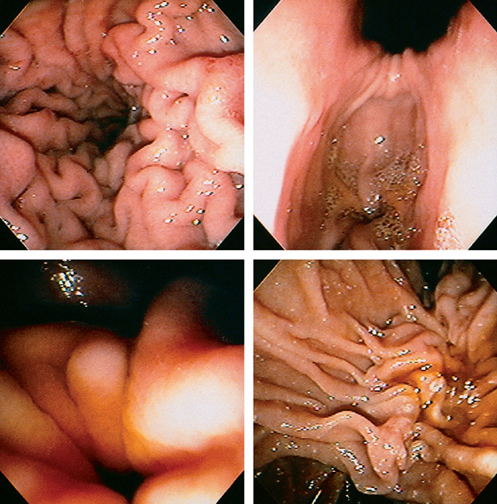
Figure 7.1 LANDMARKS
Typical view of the mid and distal stomach, with the duodenoscope tipped down and the patient prone. The lesser curvature is at the top (posterior) and the greater curvature is at the bottom (anterior; top left). With advancement of the duodenoscope to the antrum, the angularis is directly above, with the pylorus in the 6 o’clock position in the distance (top right). To advance the endoscope into the duodenum, the pylorus should be in the 6 o’clock position (bottom left). On entering the duodenal bulb, the endoscope is deflected to the right, advanced, and then withdrawn, revealing the normal position of the major papilla. In this patient, the papilla cannot be directly visualized, but its normal position can be ascertained by the presence of the longitudinal fold, which leads proximally to the papilla, as well as by the presence of bile. The papilla appears to sit on a ledge (bottom right).
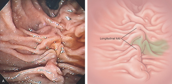
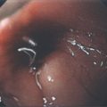
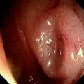
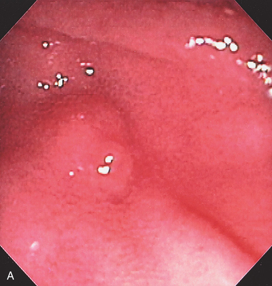
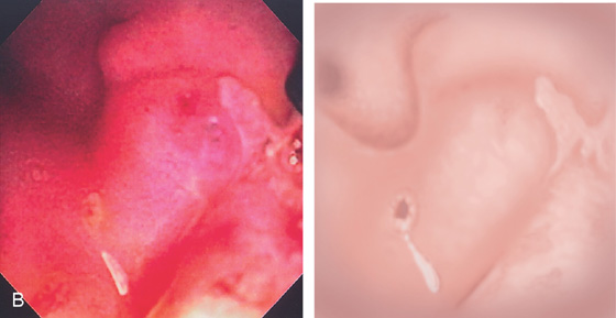
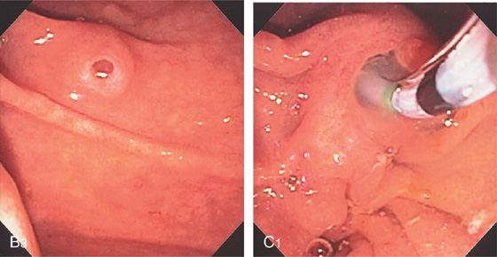
Figure 7.2 HIDDEN AMPULLA
Bile can be seen draining from the middle of this longitudinal structure, with no ampullary orifice identified (A).
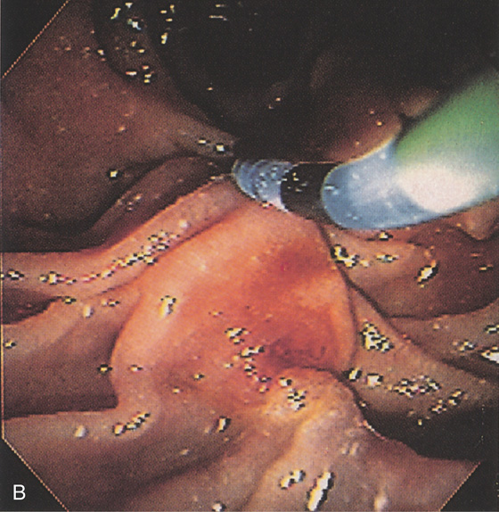
The hooded fold is lifted by the diagnostic catheter, demonstrating the pinkish color of the ampullary orifice (B). The longitudinal fold is a landmark to the papilla.
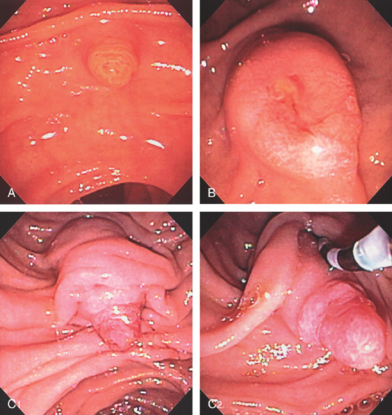
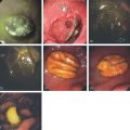
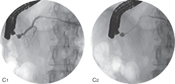
Figure 7.3 THE MANY FACES OF THE MAJOR PAPILLA
A, Small papilla in a jaundiced patient. B, The papilla is more bulbous with exudate and erythema at the papilla. This patient had gallstone pancreatitis. C1, More pronounced major papilla. When the hooded fold is moved with the catheter, the intraduodenal segment with protruding epithelium is appreciated (C2).
D1, The papilla is situated under duodenal folds with ampullary tissue visible. When viewed in the appropriate position, the biliary sphincter can be seen in the ampullary orifice (D2).
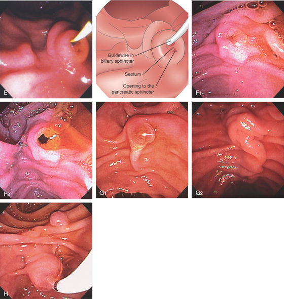
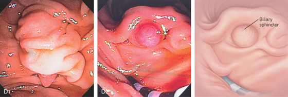
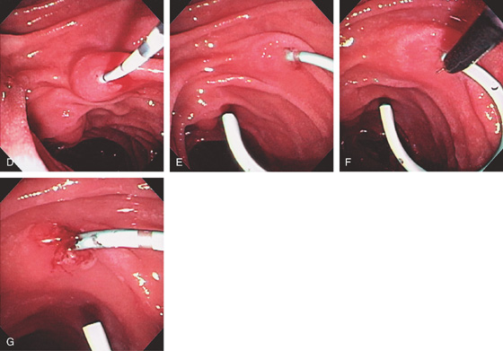
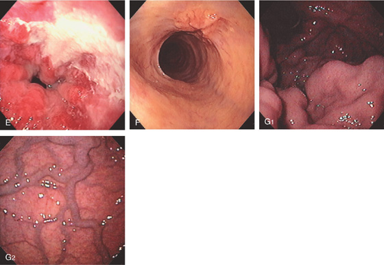
Figure 7.3 THE MANY FACES OF THE MAJOR PAPILLA
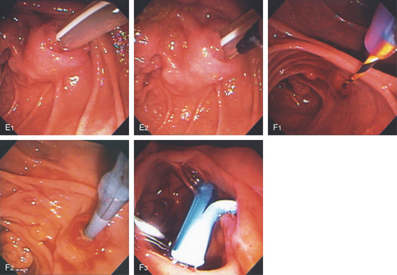
E, A guidewire is present in the biliary sphincter, and the opening to the pancreatic sphincter is shown inferiorly. The septum between the two ducts is also apparent. F, The major papilla is normal, and the biliary sphincter relaxes with flow of bile (F1, F2). G, Variable length of the longitudinal fold leading to the ampulla (G1, G2). H, The minor papilla is often visible in a lateral superior orientation.
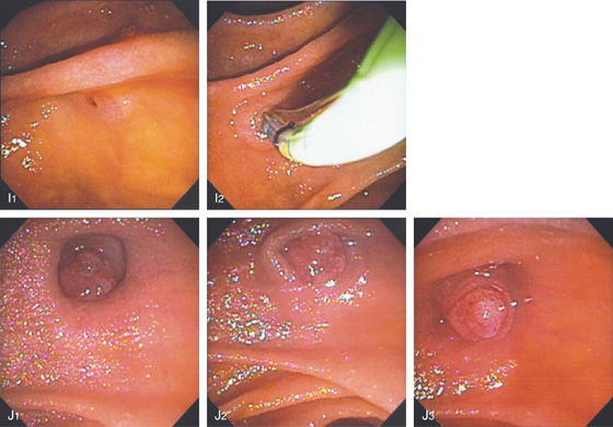
Figure 7.3 THE MANY FACES OF THE MAJOR PAPILLA
I1, I2, Major papilla is in a small diverticulum and is flat, but with cannulation the papilla becomes more pronounced. J1-J3, The papilla is situated in a diverticulum but is seen to prolapse out.
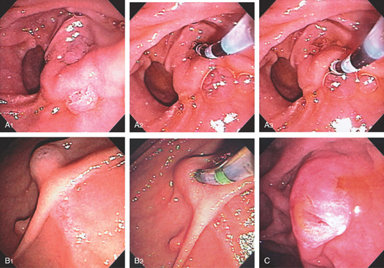
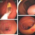
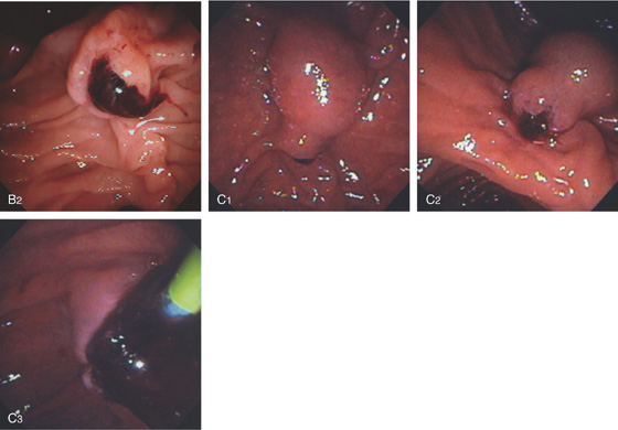
Figure 7.4 SEPARATE OPENINGS FOR THE BILE AND PANCREATIC DUCTS
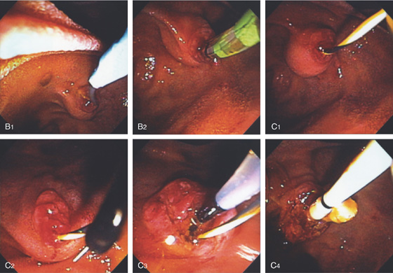
A1, Major papilla alongside a diverticulum with fleshy tissue both above and below a fold. A2, The bile duct is selectively cannulated. A3, The fleshy tissue inferiorly is cannulated confirming the pancreatic segment. B1, A structure resembling the ampulla is seen above a longitudinal fold with ampullary tissue. Underneath the fold, typical ampullary epithelium is also shown. B2, A sphincterotome is used to selectively cannulate the bile duct. C, Bile exits from an opening on the superior surface of the ampulla. A slitlike area in the middle of the papilla represents the pancreatic segment. The patient has previously undergone biliary sphincterotomy.
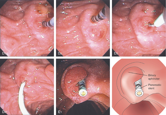
Figure 7.4 SEPARATE OPENINGS FOR THE BILE AND PANCREATIC DUCTS
D, A manometry catheter is in the pancreatic sphincter(D1). The manometry catheter is in the biliary sphincter (D2). D3, D4, A pancreatic stent is deployed in the pancreatic duct. E1, The patient has previously undergone pancreatic sphincterotomy, and a pancreatic stent is visible. The biliary sphincter is at the 11 o’clock position.
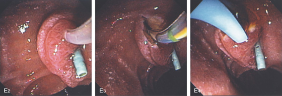
E2, The bile duct is selectively accessed. E3, Biliary sphincterotomy is performed. E4,A bile duct stent is now present.
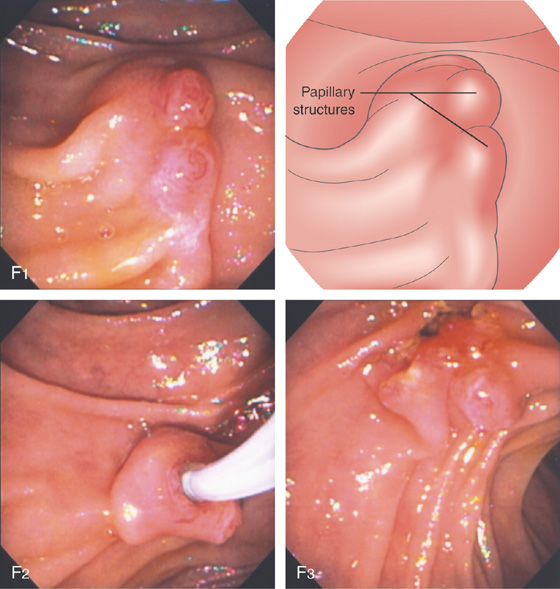
Figure 7.4 SEPARATE OPENINGS FOR THE BILE AND PANCREATIC DUCTS
F1, Two distinct papillary structures. The bile duct has been cannulated (F2) and sphincterotomy performed. Note the opening to the bile duct and the papillary structure inferiorly representing the pancreatic sphincter (F3).
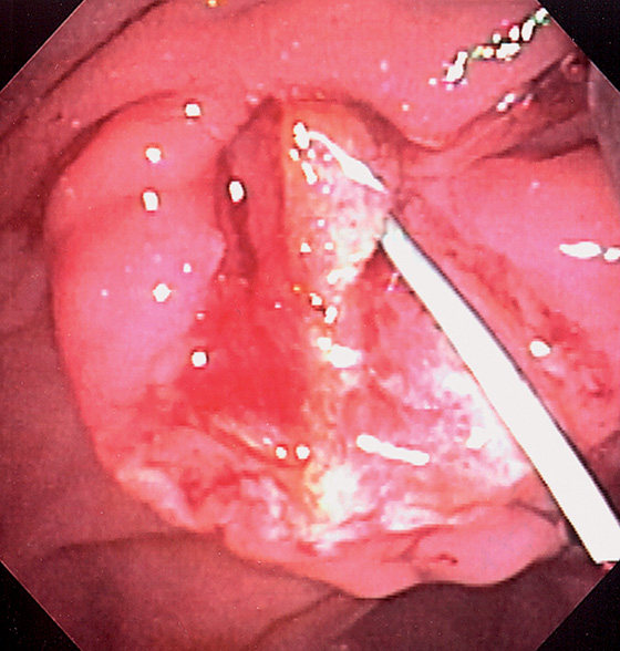
Figure 7.5 INTRAAMPULLARY SEPTUM
Both biliary and pancreatic sphincterotomies were performed with a pancreatic stent in place. Note the thick septum dividing the two openings.
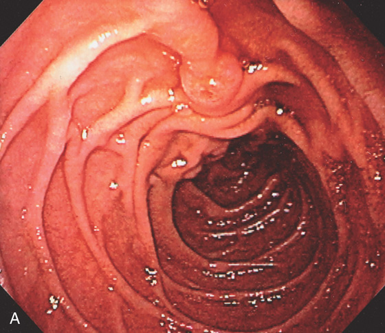
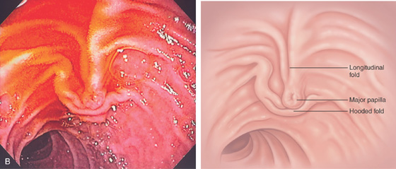
Figure 7.6 POSITION OF MAJOR PAPILLA WITH BILLROTH II ANATOMY
Note the inverse relation of the longitudinal fold to the hooded fold over the major papilla (A, B).
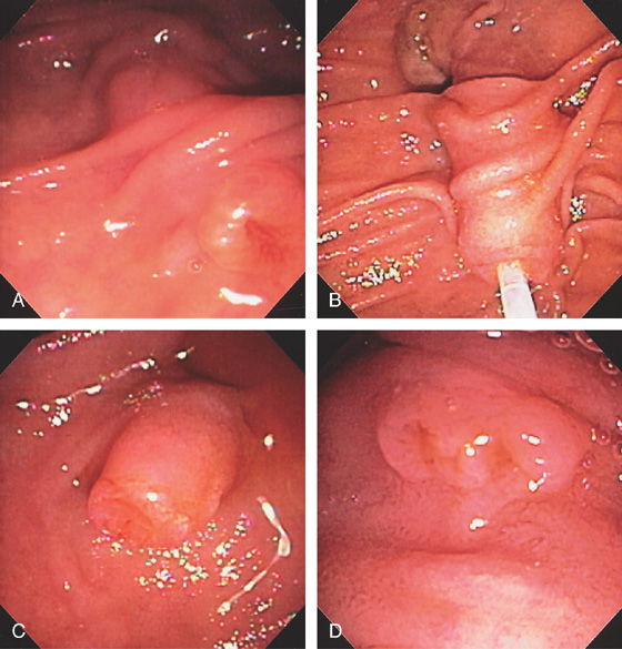
Figure 7.7 INTRADUODENAL SEGMENT OF COMMON BILE DUCT
A, Note the long intraduodenal segment. The length of the intraduodenal segment dictates the length of the sphincterotomy incision. B, Catheter in bile duct. C, Intraduodenal segment easy to identify as it appears separate from the duodenal wall. D, Very small segment.
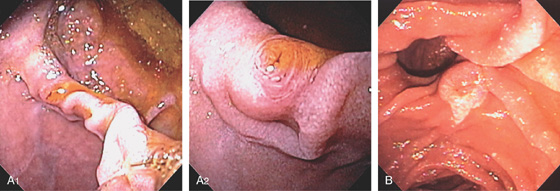
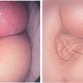
Figure 7.8 POSITION OF AMPULLA ON DIVERTICULUM
A1, Ampulla residing on the diverticular ridge. A2, Close-up shows the small ampullary structure. B, Ampullary structure at the 5 o’clock position.
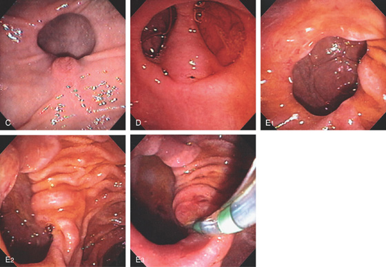
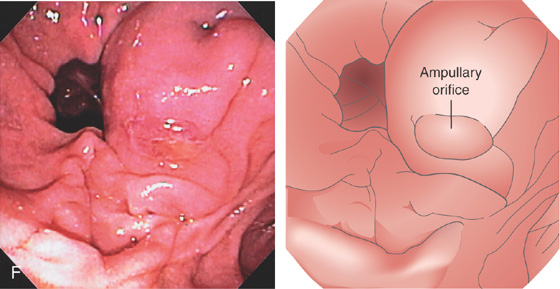
Figure 7.8 POSITION OF AMPULLA ON DIVERTICULUM
C, Ampullary structure at the 6 o’clock position. D, Large intraduodenal segment occupying the center of the diverticulum. E1, Diverticulum with no ampullary structure visible. E2, View of the diverticulum from a distance shows a small area compatible with the papilla on the inside lip at the 5 o’clock position. E3, A sphincterotome has been used to move the ampullary tissue toward the lumen. F, Bulbous ampulla occupying the inferior lip of a diverticulum. Cannulation confirmed an impacted stone.
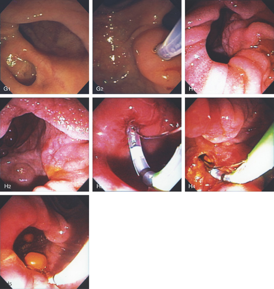
Figure 7.8 POSITION OF AMPULLA ON DIVERTICULUM
G1, The ampulla is located in a small diverticulum inferior to a larger diverticulum. G2, After selective biliary cannulation, the ampulla appears to be withdrawn from the diverticulum. H1, The ampullary orifice is on the 3 o’clock position deep inside a large diverticulum. H2, The diverticulum had to be entered for selective cannulation. H3, The diverticulum is gently entered and sphincterotome used for selective bile duct access. H4, Biliary sphincterotomy performed and a solitary stone removed (H5).
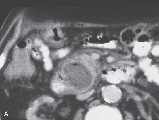
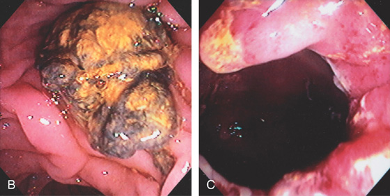
Figure 7.9 DIVERTICULUM WITH DEBRIS
A, Large duodenal diverticulum with amorphous debris and air. This patient had a bile duct obstruction. B, Mass of debris obscures the ampulla. C, The debris was ultimately removed, exposing a large periampullary diverticulum. Bile duct obstruction in this setting has been termed Lemmel syndrome. In this patient, jaundice resolved after removal of the debris.
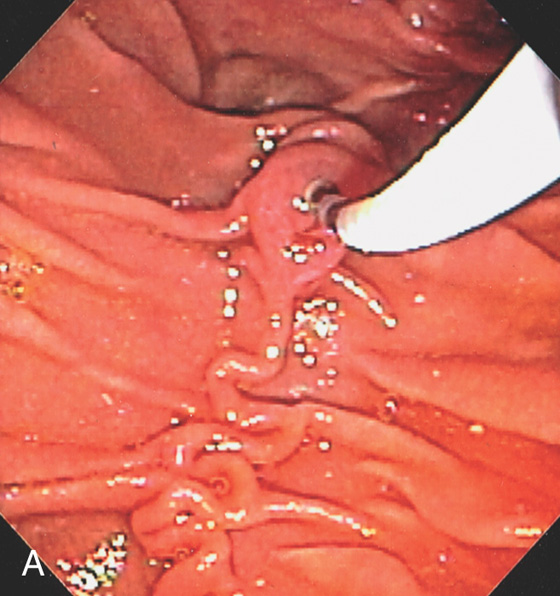
Figure 7.10 BILIARY CANNULATION TECHNIQUES
A, The bile duct was selectively cannulated from a distance that takes advantage of the curve in the catheter. Note the direction toward the 11 o’clock position. A tortuous longitudinal fold leads to the ampulla.
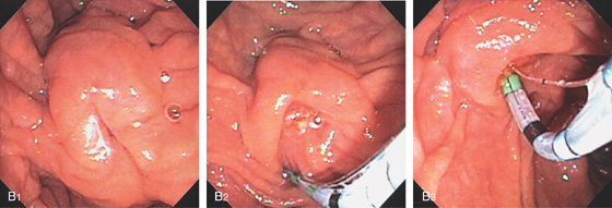
B1, The major papilla is bulbous, and overlying duodenal mucosa hides the ampullary orifice. B2, A sphincterotome is used to push away duodenal mucosa, exposing the ampullary structure. B3, Given the more en face position and need for biliary cannulation, a bowed sphincterotome was used for selective cannulation.
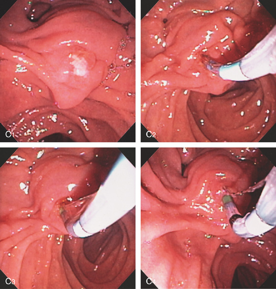
Figure 7.10 BILIARY CANNULATION TECHNIQUES
C1, Exudate covers the ampullary tissue resulting from recent previously failed cannulation. C2, A sphincterotome is placed just inside the ampullary structure toward the 11 o’clock position. C3, C4, The sphincterotome is slowly bowed, the elevator dropped, and the sphincterotome slowly advanced, which helps orient to the 11 o’clock position.
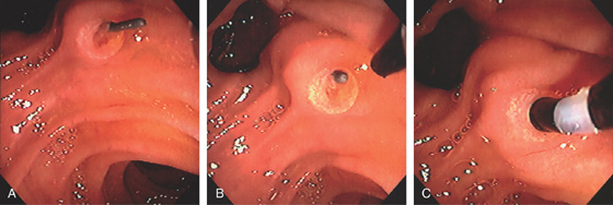
Figure 7.11 RENDEZVOUS FOR BILIARY CANNULATION
A, This patient has a T-tube in place. A wire is passed through the T-tube and out of the ampulla. B, A diagnostic catheter is placed toward the wire. C, The wire is fed into the catheter, and the catheter is then advanced into the bile duct.
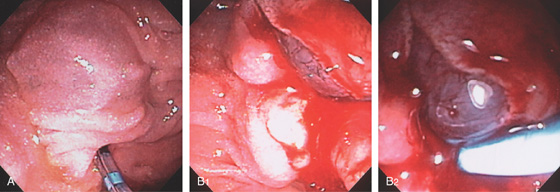
Figure 7.12 INTRAMUCOSAL CONTRAST INJECTION
A, Purplish hue to the ampullary structure. B, After biliary sphincterotomy, the underlying mucosa is hemorrhagic. A biliary stent was inserted.
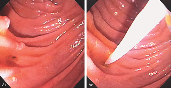
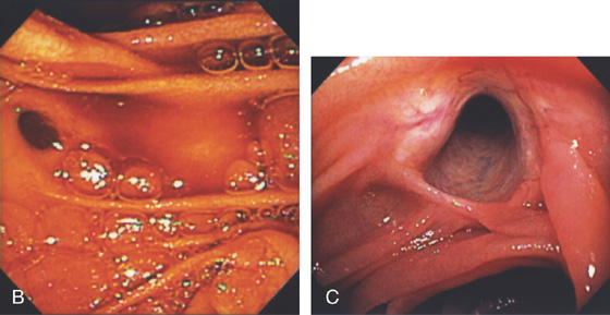
Figure 7.13 BILIARY OPENING AFTER WHIPPLE PROCEDURE
A1, Biliary anastomosis after Whipple procedure. Note the small subtle opening to the bile duct. A2, A biliary catheter has been placed into the duct. B, Distinct orifice draining bile. C, Large anastomosis with the bile duct easily visible.
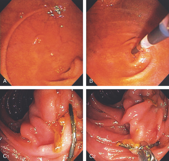
Figure 7.14 TERMINATION OF AFFERENT LIMB AFTER WHIPPLE PROCEDURE
A, Termination of the afferent limb. B, The ECRP catheter is pointing to the entrance to the pancreatic duct. The pancreatic duct is anastomosed in variable positions (see below). C1, In this patient, the pancreatic duct was anastomosed more distally. A stent is present. C2, The stent is grasped with forceps. Note a small suture is present superiorly.
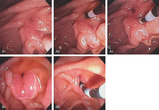
Figure 7.15 POSITION OF PANCREATIC DUCT AFTER BILIARY SPHINCTEROTOMY
A1, Note the opening of the biliary duct in relation to the pancreatic sphincter. A2, The diagnostic catheter is placed in the biliary tree. A3, The catheter is placed in the pancreatic duct. B1, Patulous biliary opening. Note the small defect immediately inferior representing the pancreatic duct. B2, The catheter is entering the pancreatic duct.
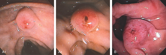
Figure 7.16 PAPILLA AFTER PASSAGE OF A STONE
A, The periampullary area is hemorrhagic, and the ampulla itself appears open. B, Hemorrhagic edematous papilla from stone passage.
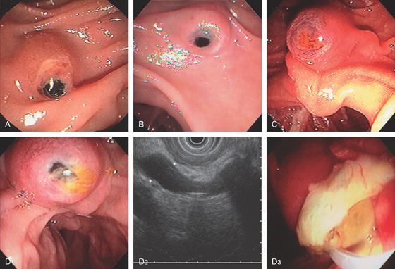
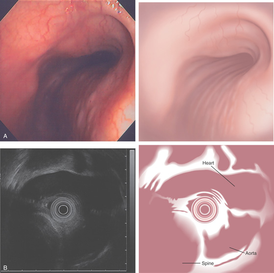
Figure 7.17 IMPACTED STONE
A-E, In each case, a bilirubinate stone is impacted at the ampulla. D1, Stone impacted in ampulla. D2, Endoscopic ultrasonography (EUS) image shows dilated bile duct with large impacted stone. Note the shadowing. D3

E2, After cannulation, a large amount of pus spontaneously passed. E1, Bilirubinate stone seen in ampullary orifice. F, Ulceration from impacted stone with impending fistula. G, Small stone in the ampullary orifice.
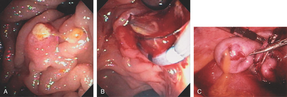
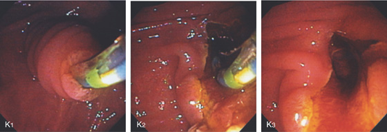
Figure 7.18 OBSTRUCTION FROM PUS
A, Yellow material obstructs the ampulla. B, With sphincterotomy, only pus passes from the obstructed duct. C, At laparoscopic cholecystectomy, thick yellow pus exudes from the gallbladder.
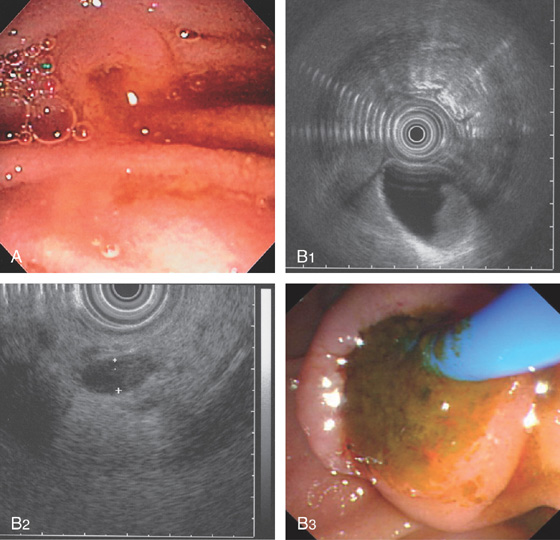
Figure 7.19 PASSAGE OF SLUDGE
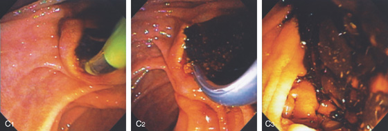
Figure 7.19 PASSAGE OF SLUDGE
C1-C3, After biliary sphincterotomy, a large amount of sludge is seen to pass.
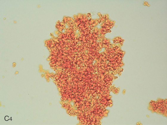
C4, Bile aspirate shows debris.
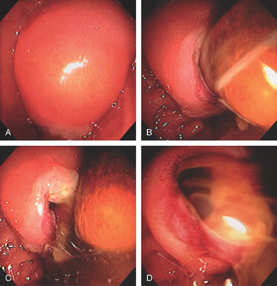
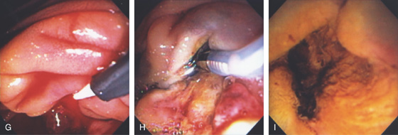
Figure 7.20 SPONTANEOUS PASSAGE OF LARGE IMPACTED STONE
A, Markedly enlarged ampulla. B, With observation, a large stone was seen to spontaneously pass, leaving a tear (C). Bile and pus now spontaneously pass from this large opening (D).
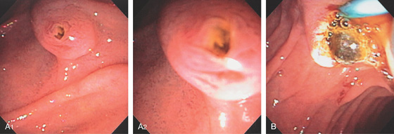
Figure 7.21 AMPULLARY STONE
A1, The ampulla is open, and on close-up (A2) a stone is visible. B, After sphincterotomy, a balloon is being withdrawn delivering a calculus.
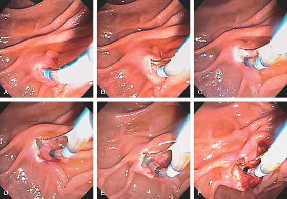
Figure 7.22 BILIARY SPHINCTEROTOMY
A, The bile duct has been selectively cannulated with a sphincterotome. B, The wire is slightly bowed. Note the length of the intraduodenal segment proximal to the large duodenal fold. C, The incision is slowly made. D, The incision is extended close to the overlying fold. E, The fold is now being incised again, noting the length of the intraduodenal segment. F, The fold is being incised.
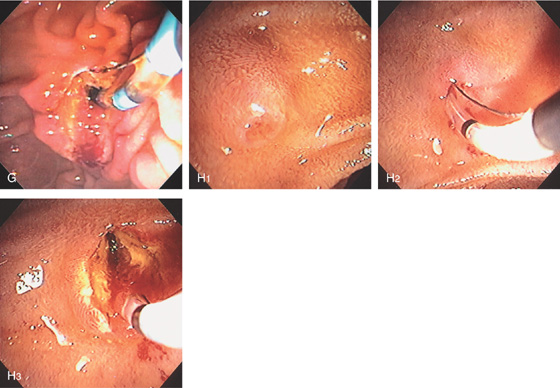
G, A small incision is made just proximal to the fold, which is the full extent of the intraduodenal segment. H1, Small papilla and intraduodenal segment. H2, A sphincterotome is bowed in the papilla. H3, Complete biliary sphincterotomy performed. Note the incision was made to the most proximal portion of the bulge in the duodenum.
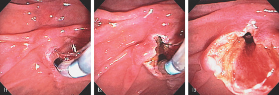
Figure 7.22 BILIARY SPHINCTEROTOMY
I1, Sphincterotome in the ampulla with selective biliary cannulation. I2, Note the incision was made over the duodenal fold and to the duodenal wall (I3).
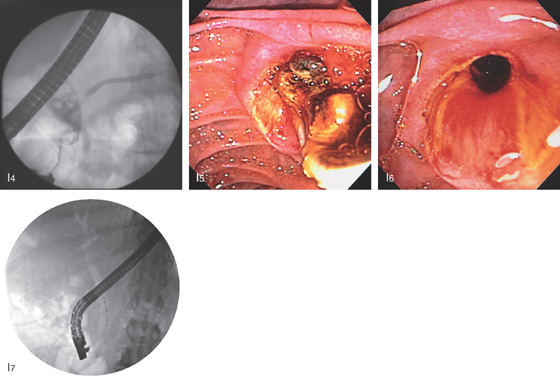
I4, Dilated bile duct with multiple stones. Contrast fills a normal distal pancreatic duct. I5, A balloon catheter is removing a large number of stones. I6, The bile duct is easily seen through the wide sphincterotomy. I7, At fluoroscopy air was now seen to outline the biliary tree, suggesting complete incision.
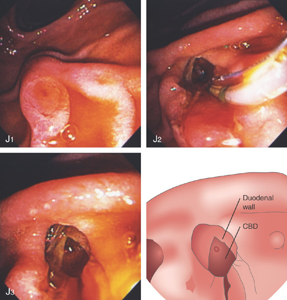
Figure 7.22 BILIARY SPHINCTEROTOMY
J1, Normal major papilla. J2, Biliary sphincterotomy is carried out to the duodenal wall just distal to the overlying fold. J3, The duodenal wall itself is now visible overlying the exposed common bile duct (CBD).
K1, Long intraduodenal bile duct segment. The sphincterotome is in the bile duct. K2, Biliary sphincterotomy performed. K3, A small portion of the duodenal wall is shown.
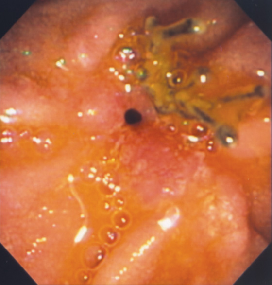
Figure 7.23 SUTURE ALONGSIDE BILIARY SPHINCTEROTOMY
Suture material is present at the site of prior sphincterotomy. This patient had duodenal oversew after duodenal perforation at the time of biliary sphincterotomy and stone removal.
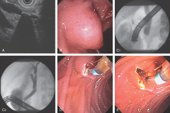
Figure 7.24 BILIARY SPHINCTEROTOMY WITH STONE REMOVAL
A, Common bile duct stone with shadowing on EUS. B, Bulbous-appearing ampulla. C1, Solitary stone on cholangiography. C2, The more proximal biliary tree is normal. Note the large number of filling defects representing gallbladder stones. D, The biliary sphincter is incised. E, The incision is performed to the duodenal wall.
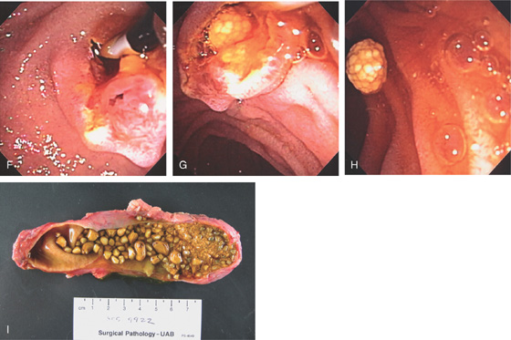
F, A balloon catheter is placed in the bile duct. Note the pancreatic sphincter is easily seen inferiorly. G, The balloon catheter is slowly removed, delivering a cholesterol mulberry-like stone. H, The stone is now completely removed and resides in the duodenum. I, The surgical specimen shows a large number of similar-appearing stones with debris.
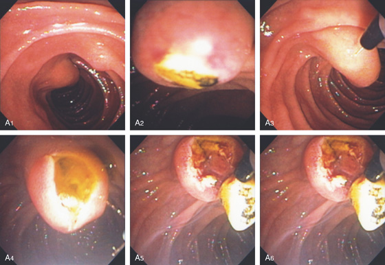
Figure 7.25 IMPACTED STONE REMOVAL
A1, A2, The major papilla is bulbous and a stone is present. A3-A5, The needle knife is used to incise the ampulla, resulting in a gush of bile and a stone. A6, The sphincterotome is used to complete the sphincterotomy.
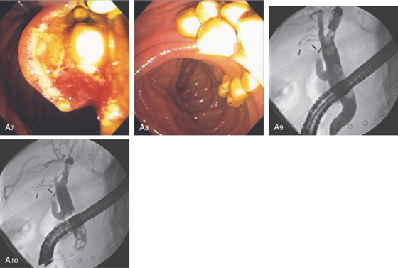
A7, A8, Multiple stones delivered. A9, Multiple large bile duct stones as shown on retrograde cholangiogram. A10, As shown on fluoroscopy, the stones are being removed with a balloon catheter.
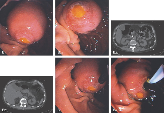
Figure 7.25 IMPACTED STONE REMOVAL
B1, B2a, Markedly enlarged papilla with impacted cholesterol stone. B2b, CT shows large stone at ampulla (arrow). A similar stone is present in the gallbladder (B2c). B3, A needle knife is used and an incision is made over the stone. B4, A large amount of dark bile passes when the biliary segment is entered.
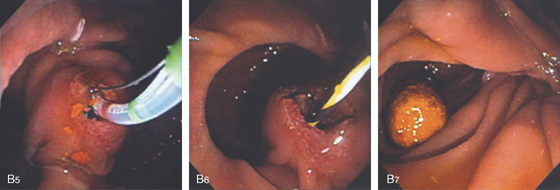
B5, B6, A sphincterotome is used to complete the incision. B7, A solitary stone is removed.
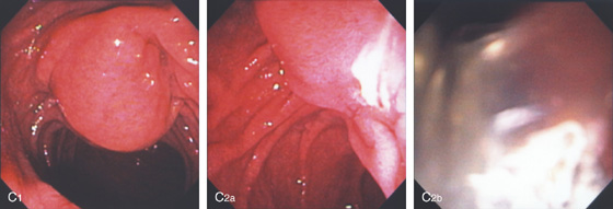
Figure 7.25 IMPACTED STONE REMOVAL
C1, The major papilla is bulbous, suggesting an impacted stone. C2a, C2b, Pus spontaneously passes from the papilla.
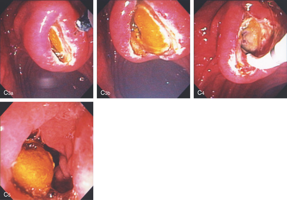
C3a, C3b, A needle knife is used and an incision is made in the ampulla revealing a stone. C4, A sphincterotome is used to complete the incision and a balloon inserted to retrieve the stone. C5, A large cholesterol stone is present.
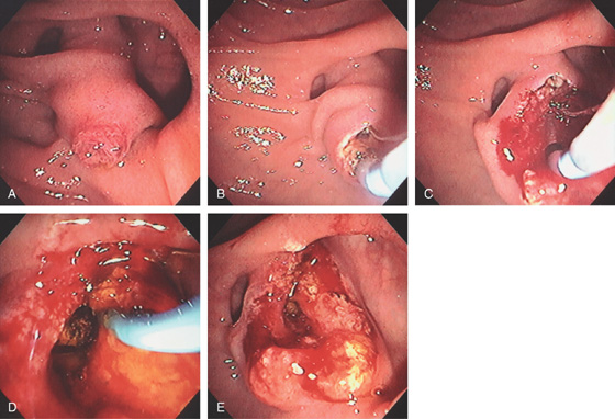
Figure 7.26 BILIARY SPHINCTEROTOMY IN DUODENAL DIVERTICULUM
A, Large intraduodenal segment extending through the diverticulum. B, The sphincterotome is placed in the ampulla and cutting begun. C, The incision is made toward the top of the intraduodenal portion. D, A stone is being removed using a balloon catheter. E, The appearance of the papilla after stone removal.
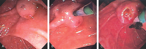
Figure 7.27 STONE IN BILIARY OPENING
A, The ampullary tissue is shown, as well as a slitlike dark opening superiorly. B, The sphincterotome is placed in the superior opening, and injection confirms the bile duct. This anatomy could be because of a separate opening of the biliary tree or a fistula from stone disease. C, After sphincterotomy, a small bilirubinate fragment can be seen.
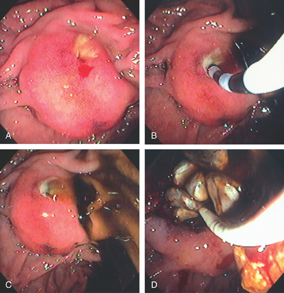
Figure 7.28 FISTULOUS OPENING ON PAPILLA FROM STONE
A, Enlarged hemorrhagic papilla with an opening on the superior portion covered with exudate. B, Cannulation of the biliary tree is performed through the fistulous opening, confirming the bile duct with multiple stones. C, After catheter removal, dark bile passes. D, Sphincterotomy was performed through the fistulous tract and numerous pearl-like stones delivered.
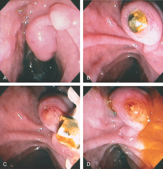
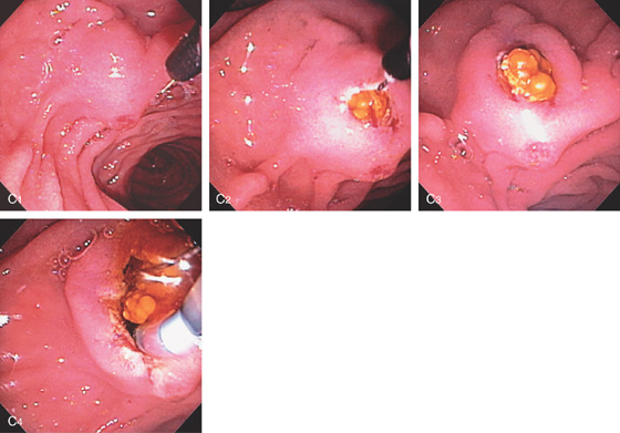
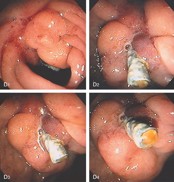
Figure 7.29 BULBOUS MAJOR PAPILLA SECONDARY TO GALLSTONE
A, The minor papilla is proximal and superior to the major papilla. B, A gallstone is impacted in the ampullary orifice. C, The stone spontaneously passes. D, Bile now exits freely. A sphincterotomy was then performed, with removal of other stones.
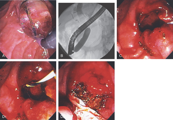
Figure 7.30 BALLOON DILATATION OF AMPULLA FOR STONE EXTRACTION
A, After biliary sphincterotomy, a 12-mm balloon is used to dilate the ampulla. B, A 12-mm balloon is placed through the ampulla and inflated, revealing a waist that was effaced. C, A large defect is shown. D1, D2, The stone is extracted.
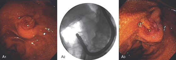
Figure 7.31 ENDOSCOPIC THERAPY IN BILLROTH II ANATOMY
A1, Note the reverse orientation of the ampulla and the duodenoscope (A2). A3, Exudate is present in the ampullary orifice.
B1, B2, Note the use of the sphincterotome and the downward orientation of the guidewire for biliary access. C1, C2, Over the wire, the needle knife is used to incise the ampulla. C3, C4, The biliary opening is now shown. The balloon is used to remove several small stones.
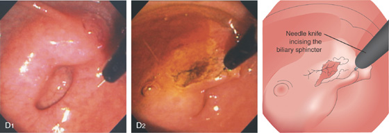
Figure 7.31 ENDOSCOPIC THERAPY IN BILLROTH II ANATOMY
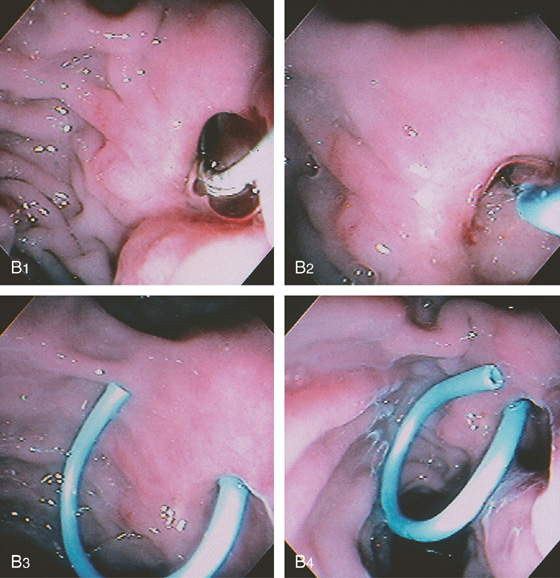
D1, The major papilla is bulbous and is located alongside a diverticulum. D2, A needle knife is used to incise the biliary sphincter.
E1, E2, A large tube is in the ampulla. The tube itself is used as a guide for needle knife biliary sphincterotomy. F1, The bile duct is selectively accessed. Note the orientation downward of the guidewire. F2, The introducer tube is placed. F3, A plastic stent is deployed.
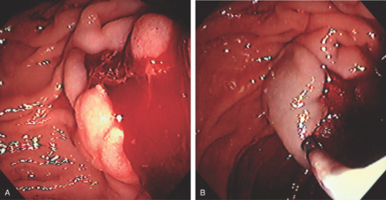
Figure 7.32 IMMEDIATE POSTSPHINCTEROTOMY BLEEDING
A, Biliary sphincterotomy has been performed with subsequent continuous stream of bright red blood. B, Dilute epinephrine is injected into the superior margin of the papilla beginning at the duodenal wall, resulting in enlargement of the papilla from the submucosal injection and marked blanching caused by ischemia.
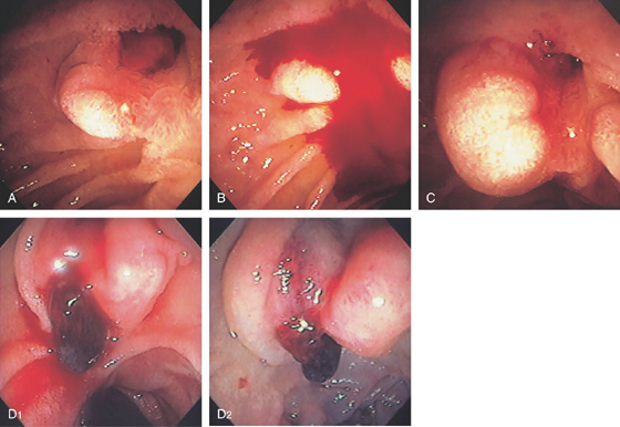
Figure 7.33 DELAYED POSTSPHINCTEROTOMY BLEEDING
A, Note the reddish visible vessel at the site of the prior sphincterotomy. B, The area was touched with the injection catheter provoking active bleeding. C, Epinephrine injection results in edema and blanching of the area with hemostasis. D1, Active oozing from a clot at the site of prior sphincterotomy. D2, After large-volume epinephrine injection, bleeding stops and there is edema and blanching of the duodenal mucosa.
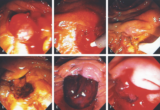
Figure 7.34 DELAYED POSTSPHINCTEROTOMY BLEEDING
A, A large, bulbous, visible vessel at the site of a prior sphincterotomy. B, Epinephrine is first injected using a standard injection needle. C, The 10-French heater probe was used to ablate the vessel (coaptive coagulation), ultimately resulting in a black eschar and hemostasis (D). E, Large blood clot occupying the ampulla. F, After clot removal, active oozing is seen.
G, Epinephrine is used to inject the area. H, The 7-French heater probe is used to ablate the vessel, resulting in hemostasis (I).
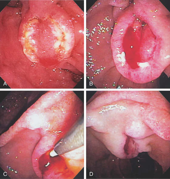
Figure 7.35 DELAYED POSTSPHINCTEROTOMY BLEEDING
A, Papilla immediately after biliary sphincterotomy. B, Patient presents with melena 1 week later. Note the postsphincterotomy appearance of the papilla with active oozing from the 11 o’clock position. C, Epinephrine injected into the area with a sclerotherapy needle. D, Note the marked blanching of the ampulla and the periampullary tissue with permanent hemostasis achieved.
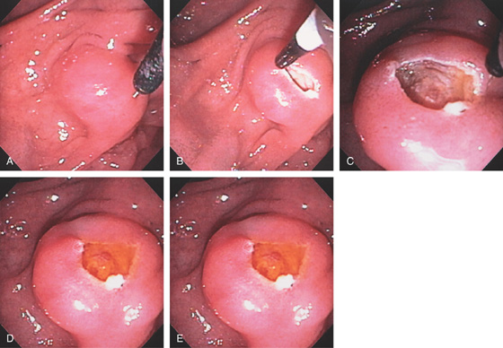
Figure 7.36 PRECUT BILIARY FISTULOTOMY
A, Note the bulbous papilla with a left-to-right orientation. A small amount of the needle knife is exposed. B, The needle is placed into the papilla and an incision made superiorly. C, The biliary sphincter has been exposed. Note the onion skin appearance of the muscle fibers. D, Bile is now shown to spontaneously flow from this area. E, The diagnostic catheter is placed into the duct and bile withdrawn, confirming selective cannulation.
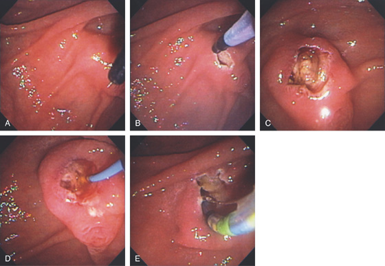
Figure 7.37 PRECUT BILIARY FISTULOTOMY
A, After failed cannulation, the needle knife is over a slightly bulbous papilla. B, The initial incision is made. C, After an additional incision, bulbous tissue is now present representing the biliary sphincter. D, E, The sphincterotome now easily enters the bile duct over a wire, and sphincterotomy is performed.
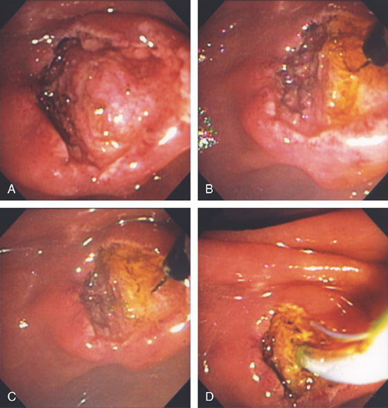
Figure 7.38 EXPOSED BILIARY SPHINCTER AFTER NEEDLE KNIFE FISTULOTOMY
A, Note the bulbous tissue underneath the duodenal mucosa after precut fistulotomy. B, The needle knife incises the tissue, resulting in drainage of bile indicative of the biliary sphincter. C, Further incision is made. D, Completion of sphincterotomy with a standard sphincterotome.
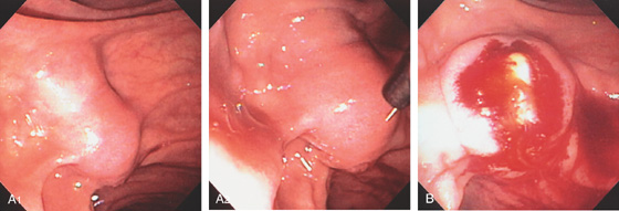
Figure 7.39 PRECUT SPHINCTEROTOMY EXPOSING AN OBSTRUCTING STONE
A1, Bulbous major papilla with long intraduodenal segment. A2, The needle knife is in the appropriate orientation. B, After incision superiorly, a stone is identified.
C1, A small portion of the needle is exposed toward the major papilla in an appropriate orientation for fistulotomy. C2, With initial small incision, yellow material is visible. C3, With further incision, a stone is visible. C4, The stone spontaneously passed, and the sphincterotomy is now extended toward the duodenal wall to remove the remaining fragments.
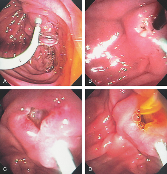
Figure 7.40 PRECUT FISTULOTOMY WITH PANCREATIC DUCT STENT
A, 5-French stent was placed into the pancreatic duct to assist in biliary fistulotomy because the papilla was small. Note the clear drainage of pancreatic juice from the stent. B, A small incision is made proximal to the stent in the location of the bile duct. C, Exposure of biliary muscle fibers. D, A diagnostic catheter is placed through the fibers and aspiration confirms selective cannulation of the biliary system.
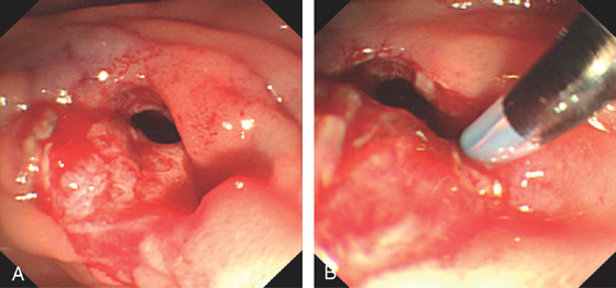
Figure 7.41 PRECUT PERFORATION
A, Large opening created by precut technique. B, Probing with a catheter exposes a large defect representing perforation.

Figure 7.42 PRIOR FAILED PRECUT FISTULOTOMY
A, Appearance of the papilla after prior attempt at fistulotomy. B, Close-up shows an area compatible with biliary muscle fibers. C, The diagnostic catheter is placed into the area and bile aspirated. D, A sphincterotomy is now performed.
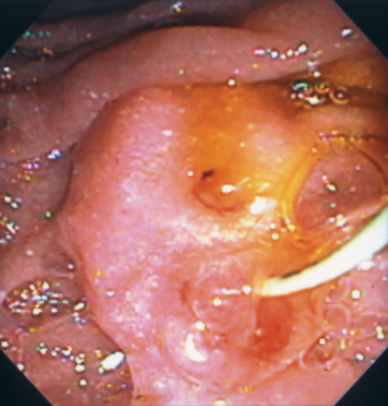
Figure 7.43 PRIOR PRECUT FISTULOTOMY
The biliary sphincter is superior to the pancreatic sphincter, where a wire is present in the pancreatic duct.
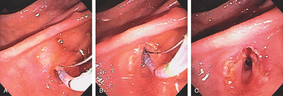
Figure 7.44 PANCREATIC SPHINCTEROTOMY
A, After selective pancreatic duct cannulation, the sphincterotome is bowed. Note the orientation toward the 1 o’clock position. B, The incision is extended to the top of the bulge in the duodenum representing the intraduodenal pancreatic duct segment. C, Appearance after complete incision of the pancreatic sphincter.
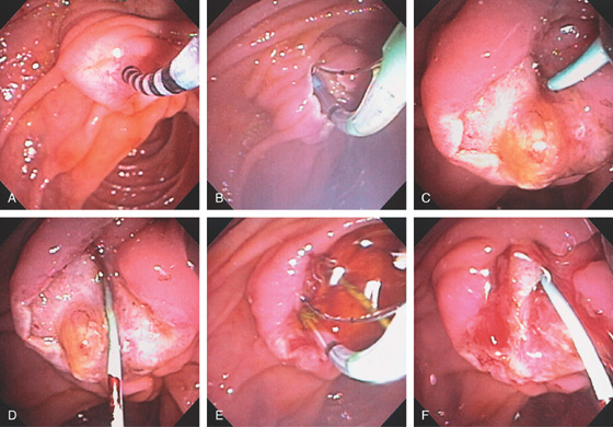
Figure 7.45 PANCREATIC AND BILIARY SPHINCTEROTOMIES
A, A manometry catheter is in the pancreatic sphincter. High pressures were documented; pancreatic and biliary sphincterotomies will be performed. B, Pancreatic sphincterotomy being performed with the pull-type sphincterotome. C, A 3-French stent is placed in the pancreatic duct. D, Note the biliary sphincter is now exposed inferiorly on close-up. E, Biliary sphincterotomy being performed. F, After biliary sphincterotomy, the intraampullary septum is now visible.
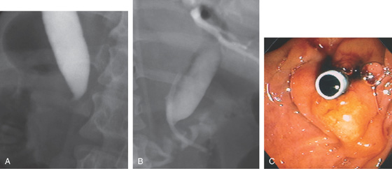
Figure 7.46 COMMON BILE DUCT STRICTURE WITH STENT PLACEMENT
A, Cholangiogram demonstrates a dilated common bile duct, which ends abruptly in the intrapancreatic portion of the common bile duct. Note the distance from the contrast in the common bile duct to the duodenal wall, demarcated by the air in the duodenum. This patient had pancreatic adenocarcinoma, resulting in a biliary stricture. B, Appropriate position of the stent in the common bile duct, with the end of the stent in the duodenum. C, The stent is observed in the prior sphincterotomy orifice. Bile is now draining freely.
D, Jaundice recurred 2 months later. The papilla appears enlarged (D1). Tissue surrounding the stent has an erythematous and villous appearance (D2, D3). Biopsy results of these abnormalities demonstrated pancreatic carcinoma. The stent is occluded (D4).
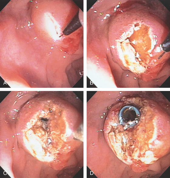
Figure 7.47 MIGRATED BILE DUCT STENT REMOVAL WITH PRECUT FISTULOTOMY
A, Selective cannulation could not be achieved as the stent was seen in the ampulla fluoroscopically. The stent is not visible in the duodenum. A needle knife was used to create a fistulotomy. B, The biliary sphincter is now visible, but no stent is shown. C, With further incision, dark material is visible, and with a complete incision, the bile duct stent is now visible (D).
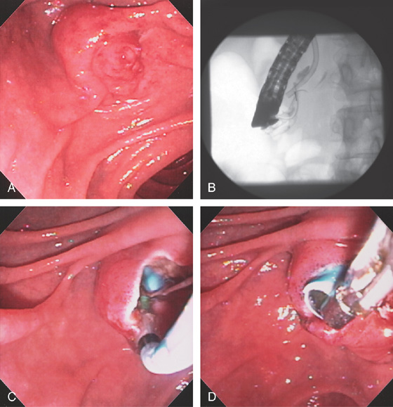
Figure 7.48 MIGRATED BILE DUCT STENT REMOVAL
A, The major papilla appears normal. B, Fluoroscopy shows the stent inside the papilla. C, A sphincterotome is used for cannulation and sphincterotomy performed exposing the stent. D, The stent is grasped with forceps and removed.
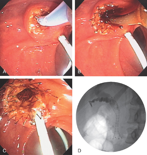
Figure 7.49 BILIARY METALLIC STENT PLACEMENT
A, Precut fistulotomy was required to access the bile duct. A pancreatic duct stent is shown. The 10-French metal stent is placed into the bile duct. Note that a small portion of the metal stent is at the level of the ampulla. B, The stent is slowly deployed, and with full deployment note that it is just at the level of the papilla. C, Note the wide opening through the metallic stent. D, Fluoroscopic image shows the location of the stent and the intrapancreatic common bile duct stricture.
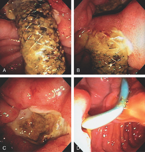
Figure 7.50 ULCER RELATED TO BILIARY METALLIC STENT
A, A significant amount of the metallic stent, placed percutaneously, resides in the duodenum. B, The distal end of the stent was impacted into the duodenal wall. C, The stent was moved from the wall with the endoscope revealing a large ulcer on the contralateral wall. D, 10-French plastic stent exiting the papilla. A large amount of the stent resides in the duodenum and is impacted in the duodenal wall, causing an ulcer crater on the lateral wall. The pancreatic stent has been removed.
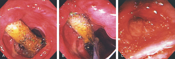
Figure 7.51 ULCER RELATED TO MIGRATED COVERED METAL BILIARY STENT WITH STENT REMOVAL
A, The coated stent has slightly migrated, resulting in ulceration in the contralateral wall. B, The stent is grasped with a standard snare and removed, resulting in a large mucosal defect (C).
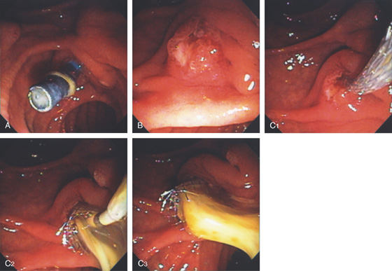
Figure 7.52 OCCLUDED PLASTIC BILIARY STENT
A, Note the absence of bile in the duodenum and the presence of debris in the stent. B, The appearance of papilla after stent removal. C1, A metallic stent has been deployed. C2, C3, Note the large amount of spontaneous passage of pus.
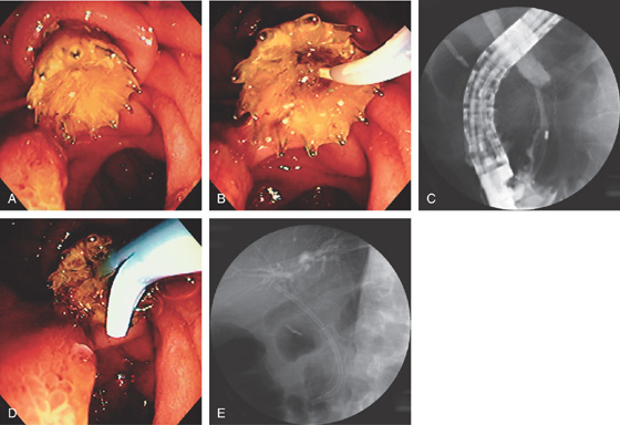
Figure 7.53 OCCLUDED METALLIC STENT
A, Debris fills the metallic stent in a patient with recurrent jaundice. B, The catheter is placed through the metallic stent. C, Injection shows tumor ingrowth with a thin stream of contrast passing proximally. D, A plastic stent is placed through the metallic stent. E, A plastic stent is placed to the common hepatic duct.
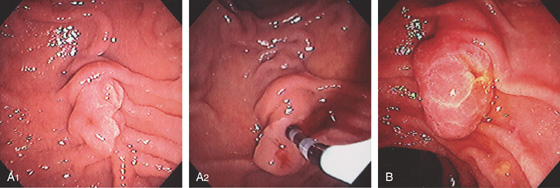
Figure 7.54 AMPULLARY ADENOMA
A1, Small adenoma of the ampulla. A2, With the catheter in the bile duct, the demarcation between the adenomatous tissue and normal ampulla is evident. B, Adenoma occupying the major papilla. Note the spontaneous passage of bile.
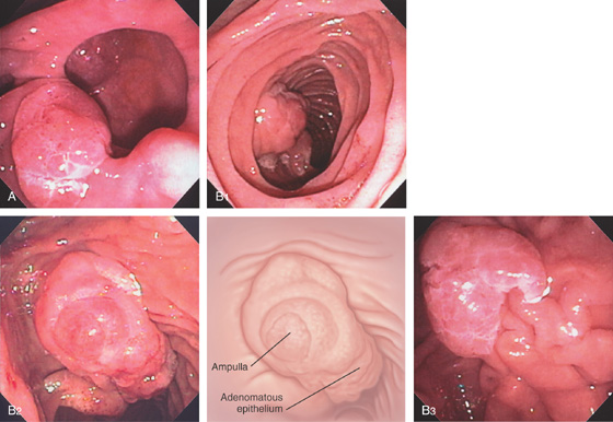
Figure 7.55 LARGE AMPULLARY ADENOMA
A, Adenoma of the papilla on the 7 o’clock position of a diverticulum. B1, Large adenoma can be seen entering the second duodenum. B2, En face view shows typical adenomatous epithelium. B3, Demarcation of the adenoma with normal duodenal mucosa is visible inferiorly.
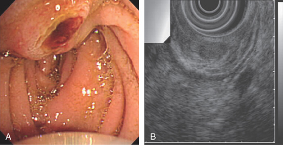
Figure 7.56 PROMINENT PAPILLA FROM ADENOMA
A, Prominent papilla. B, EUS shows an intrapapillary structure with a filling defect.
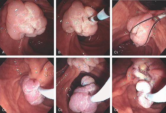
Figure 7.57 AMPULLECTOMY FOR ADENOMA
A, Characteristic-appearing adenoma occupying the ampulla. The adenoma has a typical whitish verrucous appearance. B, With probing of the lesion, the sphincter cannot be localized. C1-C4, A snare is used, and the adenoma removed in a piecemeal fashion.
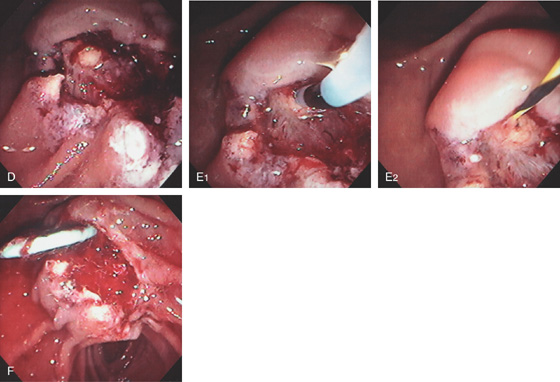
D, After removal of the adenoma, a round yellow structure is exposed representing the pancreatic sphincter. E1, The yellowish structure representing the pancreatic sphincter is now selectively cannulated, and a wire is placed (E2). F, A pancreatic duct stent is placed to prevent pancreatitis.
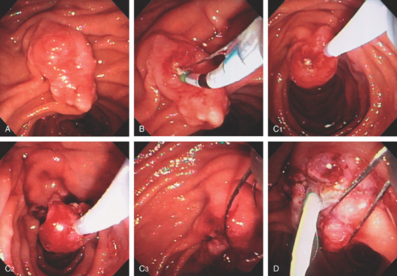
Figure 7.58 AMPULLECTOMY FOR ADENOMA
A, Adenoma occupying the major papilla. Ampullary tissue is visible. B, The pancreatic duct is selectively cannulated and pancreatic duct sphincterotomy performed for later stent placement. C1-C3, The ampullary adenoma is removed using snare techniques. D, A pancreatic duct stent is placed and additional polyp removed with a snare.
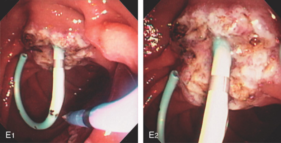
E1-E2, Additional adenomatous tissue is ablated by argon plasma coagulation.
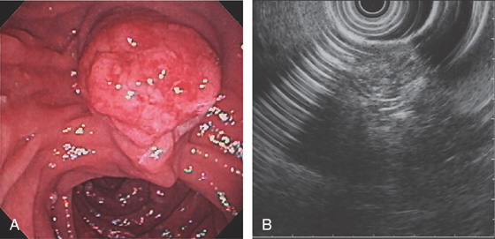
Figure 7.59 AMPULLARY ADENOMA IN FAMILIAL ADENOMATOUS POLYPOSIS SYNDROME
A, Adenoma involving the ampulla. Additional small adenomas are in the descending duodenum. B, EUS shows a lesion indistinguishable from the surrounding structures. A Whipple pancreaticoduodenectomy was performed.
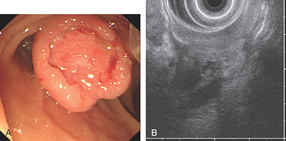
Figure 7.60 AMPULLARY CANCER
A, Enlarged ulcerated ampulla. B, The tumor is locally advanced invading the pancreas as shown by EUS.
A1, Prominent papilla resembling a thumb. A2, The ampullary tissue appears prominent. A3, A biliary brush was used to diagnose malignancy.
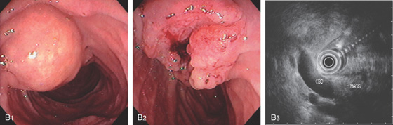
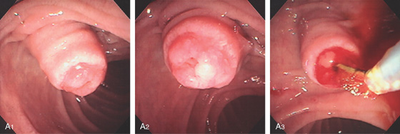
Figure 7.61 AMPULLARY CANCER
B1, The major papilla appears enlarged. Note the location of the adjacent minor papilla. B2, En face view shows the ampulla to be ulcerated, which is characteristic of carcinoma. B3, EUS shows a dilated bile duct ending in a mass lesion.
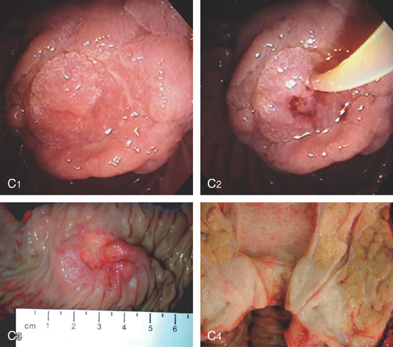
C1, Ulceration at the ampulla. C2, The bile duct was cannulated as shown by aspiration of bile. An attempt should be made to localize the bile duct because multiple cannulation attempts will induce bleeding. C3, Surgical specimen shows the large ulcerated papilla. C4, Ampullary tumor in cross sections shows the short segment of tumor and the marked dilatation of the more proximal biliary tree.
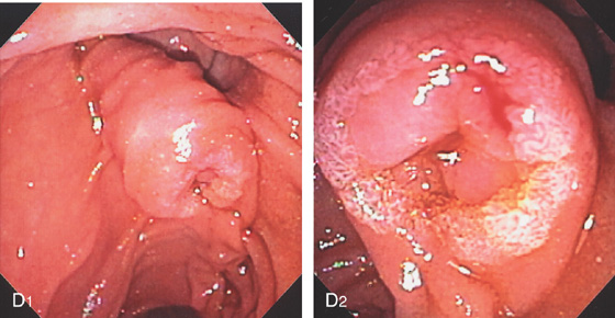
Figure 7.61 AMPULLARY CANCER
D1, Markedly enlarged intraduodenal segment of the bile duct. D2, The ampullary orifice is prominent and friable, suggestive of underlying tumor.
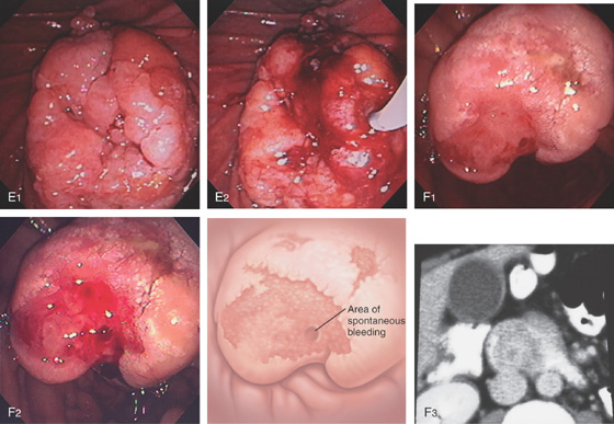
E1, Polypoid mass of the ampulla. E2, Identifying the ampulla was challenging and found on the lateral margin. F1, The ampulla is enlarged and ulcerated. F2, With observation, spontaneous bleeding was apparent. F3, The ampullary mass occupies a majority of the duodenal lumen, as shown on CT scanning. Note the dilated gallbladder.
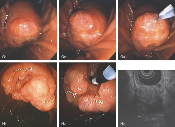
Figure 7.61 AMPULLARY CANCER
G1, Note the bulbous papilla. G2, The ampullary orifice itself is ulcerated. G3, A glidewire is used to access what appears to be the biliary sphincter. H1, Large, bulbous, ulcerated ampulla. H2, Biliary orifice is identified and selective cannulation achieved. H3, The ampullary cancer as shown on EUS.
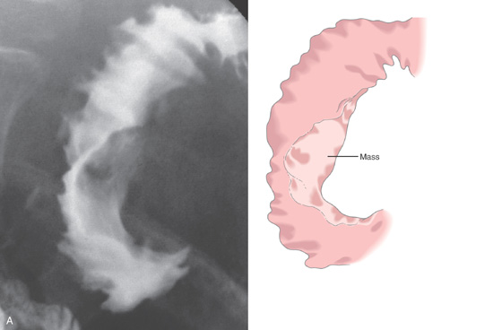
Figure 7.62 AMPULLARY CARCINOMA
A, Barium study demonstrates a mass lesion on the medial wall of the second duodenum, extending into the lumen.
B, Contrast in the second duodenum is displaced by the mass.
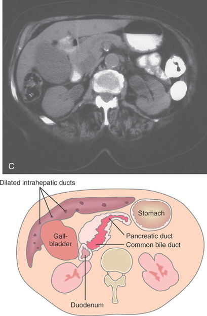
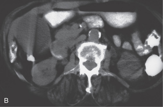
C, The pancreatic duct and common bile duct are dilated, suggesting distal obstruction. The gallbladder is also large, with dilation of the intrahepatic ducts.
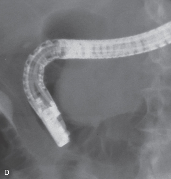
Figure 7.62 AMPULLARY CARCINOMA
D, With the duodenoscope in the standard position, a mass is clearly seen compromising the duodenal lumen.
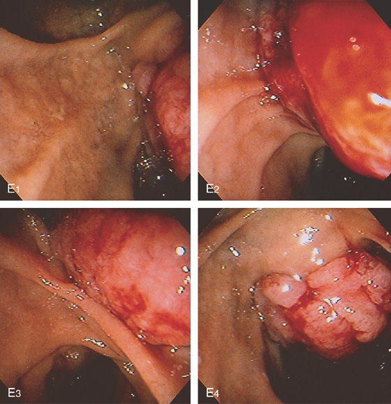
E, A large cancer is on the medial wall at the level of the normal papilla.
F, A pigtail catheter is placed percutaneously for drainage. The common bile duct is dilated.
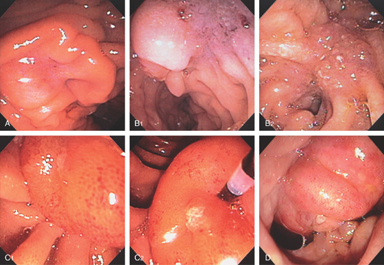
Figure 7.63 ABNORMAL PAPILLA CAUSED BY PANCREATIC CANCER
A, Purplish hue with retraction on the superior portion of the ampulla. B1, Purplish hue superior to the ampulla. B2, On close-up, there is villous-appearing tissue more superiorly with narrowing of the duodenum. This patient had jaundice and a pancreatic duct stricture. Biopsy of the area showed adenocarcinoma. C1, Large bulging ampulla. C2, The diagnostic catheter is used to expose the ampulla. D, Masslike appearance of the papilla. Note the ampulla distally with protruding tissue.
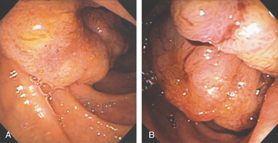
Figure 7.64 DUODENAL CANCER INVOLVING THE AMPULLA
A, B, Hemicircumferential ulcerated mass lesion involving the medial wall of the duodenum. Note the villous appearance of the tumor.
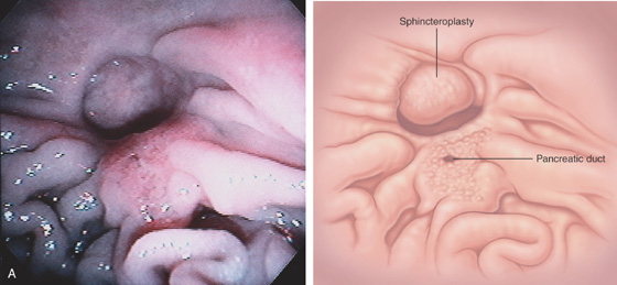
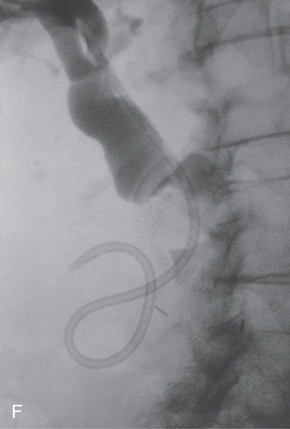
Figure 7.65 SURGICAL SPHINCTEROPLASTY AND PLACEMENT OF A PIGTAIL STENT
A, The opening to the common bile duct is to the left. The pancreatic sphincter is demarcated by the slitlike opening, with surrounding villous-appearing tissue.
B, The diagnostic catheter is removed over a guidewire (B1), and a 7-French pigtail stent is advanced over the wire (B2). The guidewire is removed with the stent in place, assuming its pigtail shape (B3, B4).
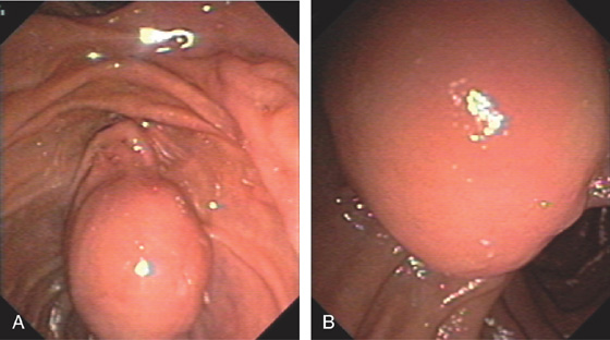
Figure 7.66 AMPULLARY GASTROINTESTINAL STROMAL TUMOR
A, B, Large bulging ampulla.
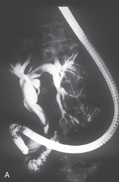
Figure 7.67 ASCARIS LUMBRICOIDES
A, A long filling defect in the bile duct on cholangiogram.
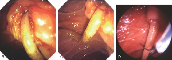
B, C, Worm exposed after sphincterotomy exiting the duct. D, Worm removed from the bile duct with a snare. (Courtesy J. L. Vazquez-Iglesias, MD, La Coruña, Spain.)
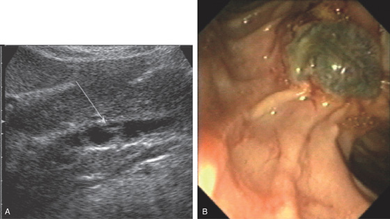
Figure 7.68 FASCIOLA HEPATICA (LIVER FLUKE)
A, Filling defect in common bile duct. B, The flat worm is on the ampulla after removal. (Courtesy J. Jimenez-Perez, MD, Pamplona, Spain.)
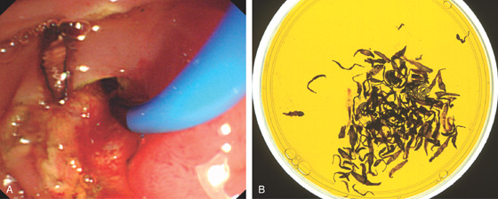
Figure 7.69 CLONORCHIS SINENSIS (LIVER FLUKE)
A, A small, flat worm is apparent after sphincterotomy. B, Multiple worms removed from the bile duct.
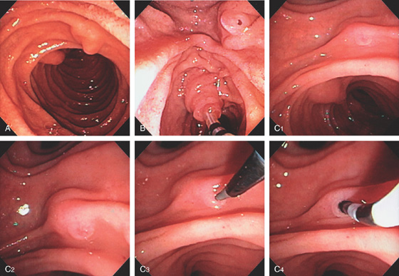
Figure 7.70 MINOR PAPILLA
A, On entering the second duodenum, the major papilla can be seen on the medial wall (left) with the minor papilla, superior and lateral. B, The minor papilla is superior and lateral to the papilla. The papilla is captured open. C1, C2, The minor papilla is prominent. The major papilla is shown distally. C3, C4, Cannulation was achieved using a standard catheter and guidewire.
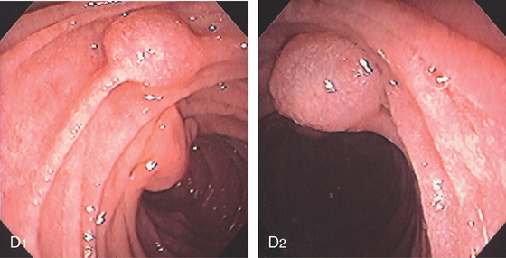
D1, Bulbous dilatation of the minor papilla as shown entering the second duodenum and on close-up (D2).
A, The minor papilla is slightly bulbous, with an area suggestive of the orifice.
B, After several failed attempts at cannulation, secretin was given. The opening is now visible, with marked flow of clear pancreatic juice.
C1, Cystic dilation at the minor papilla diagnostic of a santorinicele. C2, Contrast has drained from the dorsal duct with residual contrast in the santorinicele.
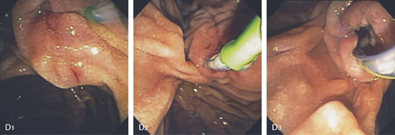
Figure 7.71 SANTORINICELE
D1, The minor papilla is exposed. D2, A small guidewire is used for cannulation followed by a standard sphincterotome. D3, Note the size of the distal pancreatic duct after sphincterotomy.
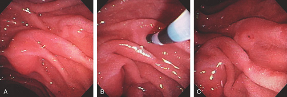
Figure 7.72 MINOR PAPILLA SPHINCTEROTOMY
A, Both the major and minor papilla are visible. B, A metal-tipped catheter is used for cannulation, and injection confirms the dorsal duct. C, After catheter removal, the sphincter is seen to open with drainage of pancreatic juice.
D, A stiff guidewire is placed in the dorsal duct. E, A 5-French single pigtail stent has been placed. F, A needle knife is exposed. G, The knife is used to incise the minor papilla, now exposing the stent.
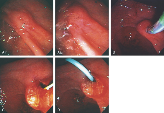
Figure 7.73 MINOR PAPILLA SPHINCTEROTOMY WITH A STANDARD PULL SPHINCTEROTOME
A, The minor papilla ampullary orifice is identified. A2, After secretin injection, pancreatic juice gushes from the orifice. B, A sphincterotome is used to cannulate the papilla. C, Sphincterotomy is performed. D, After wire placement, a 5-French single pigtail stent is placed.
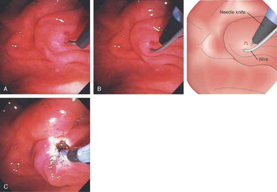
Figure 7.74 INCISION OF MINOR PAPILLA OVER AN INSERTED WIRE
A, Neither the standard catheter nor the 5-4-3 catheter entered the strictured orifice over a small wire. B, A needle knife was placed alongside the wire and incision performed. C, The catheter now enters the duct, and a stent is deployed.
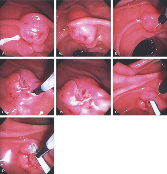
Figure 7.75 MINOR PAPILLA PRECUT FISTULOTOMY
A1, A2, The minor papilla is bulbous and selective cannulation could not be achieved. Because of its large size, the minor papilla resembles a major papilla. B1-B3, A needle knife is used to incise the papilla, exposing the duct. C, Selective cannulation is achieved and a stent ultimately deployed. D, The incision is completed with a needle knife incision made over the stent.
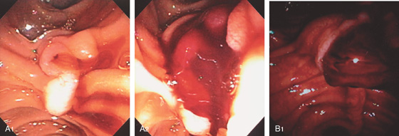
Figure 7.76 HEMOBILIA
A1, A2, Fresh blood emanating from the major papilla. B1, Large blood clot emanating from the papilla with fresh blood in the duodenum.
B2, The periampullary area was washed, revealing thick fresh clot on the papilla. C1. C2, The papilla is bulbous with clot in the orifice. C3, A small sphincterotomy is performed and a large blood clot passes spontaneously.
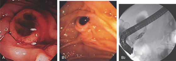
Figure 7.77 HEMOSUCCUS PANCREATICUS
A, The minor papilla is gaping with mucus, blood clot, and fresh bleeding. This patient has IPMN (intrapancreatic mucinous neoplasm), and fine needle aspiration biopsy of a lesion was performed, which precipitated the bleeding as shown 1 hour later. B1, Clot overlying the ampulla. B2, Clot fills the pancreatic duct.
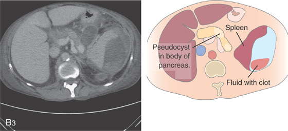
B3, A pseudocyst in the pancreatic body with clot. Note there is also fluid with clot surrounding the spleen.
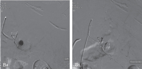
B4, Arteriogram demonstrates the cystic structure (pseudoaneurysm), which is embolized (B5).
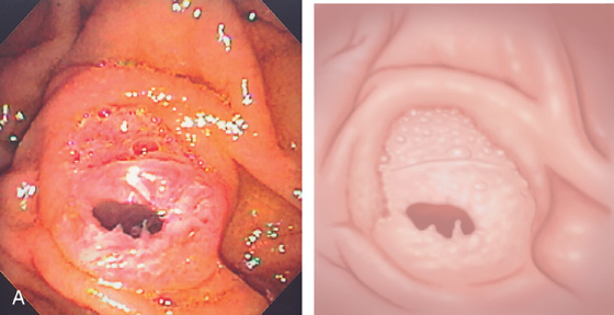
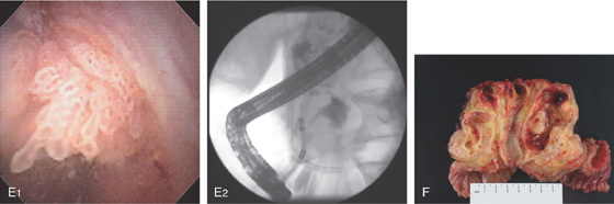
Figure 7.78 INTRADUCTAL PAPILLARY MUCINOUS NEOPLASM
A, Fish mouth appearance of the major papilla with the presence of gelatinous mucus.
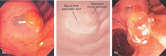
B1, Papilla is bulbous with a large amount of mucus and displacement of the biliary sphincter. B2, Spontaneous gush of a large quantity of mucus.
B3, Note that mucus is also passing from the minor papilla. C1, The pancreatic duct is easily cannulated with a sphincterotome.
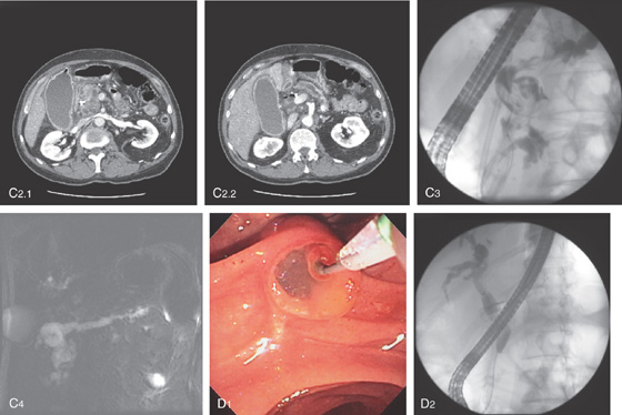
Figure 7.78 INTRADUCTAL PAPILLARY MUCINOUS NEOPLASM
The pancreatic duct is grossly dilated in the head (C2.1) and body (C2.2). C3, Dilated mucus-filled pancreatic duct. Note the biliary stent. C4, Dilated pancreatic duct as shown on magnetic resonance cholangiopancreatography. D1, The bile duct sphincter, pushed laterally from the mucus, is selectively cannulated with a wire. D2, Stricture of the intrapancreatic bile duct.
E1, Pancreatoscopy shows the frondlike projections representing the papillary tumor. E2, The small endoscope shown fluoroscopically in the duct. F, Whipple resection shows dilated pancreatic duct with a mucosal nodule. Adenocarcinoma was found histologically.
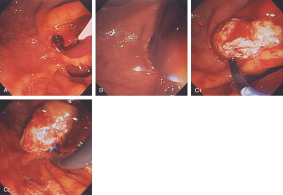
Figure 7.79 INTRADUCTAL NEOPLASM
A, A small amount of blood is alongside the wire in the bile duct. B, Sphincterotomy is performed followed by a gush of bile mixed with blood. C1, C2, A balloon is used to remove a large fragment of tissue confirmed to be hepatocellular cancer.
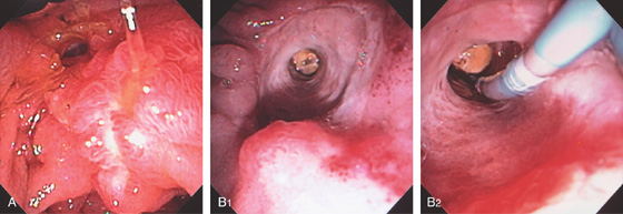
Figure 7.80 SURGICAL SPHINCTEROPLASTY
A, Recent sphincteroplasty performed showing edema around the biliary opening. B1, A large defect with an impacted stone. B2, A balloon is used to remove a stone.
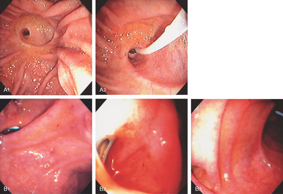
Figure 7.81 CHOLEDOCHODUODENOSTOMY
A1, Large defect in the duodenal wall just lateral to the ampulla. A2, Close-up shows a catheter in the bile duct. B1, Stent in the duodenal wall at the site of side-to-side choledochoduodenostomy. B2, Close-up of the defect shows the top-most portion of the bile duct stent with the stent exiting the ampulla in the distance (B3).
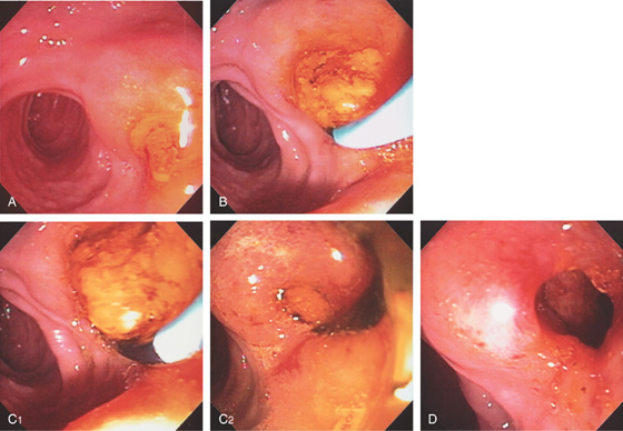
Figure 7.82 CHOLEDOCHODUODENOSTOMY WITH STONES
A, Bulging defect in duodenum covered with sludge. B, Cannulation with a balloon catheter. C1, C2, A large stone is removed. D, Large opening apparent after the stone and sludge were removed.
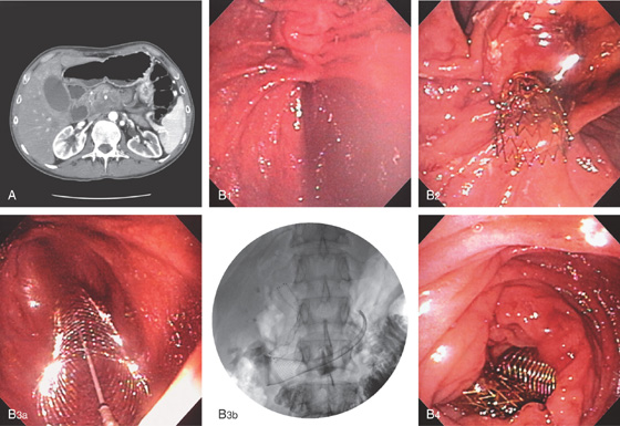
Figure 7.83 DUODENAL OBSTRUCTION FROM PANCREATIC CANCER
A, Large, hyperdense pancreatic mass with arterial encasement. Note the dilated stomach and duodenum to the level of the tumor, as well as dilated gallbladder. B1, Dilated duodenum with marked amount of retained fluid from the distal duodenal obstruction. B2, Biliary metal stent has been deployed. B3, Both metal prostheses are shown (B3a). The distal end of the duodenal stent has not yet fully deployed (B3b). B4, Both metal stents are visible in duodenum.
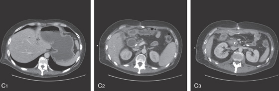
Figure 7.83 DUODENAL OBSTRUCTION FROM PANCREATIC CANCER
C1, Markedly dilated stomach with air in the biliary tree from prior percutaneous transhepatic cholangiogram. C2, The duodenum is also markedly dilated to the level of the percutaneously placed stent. C3, Large pancreatic mass lesion encases the stent.
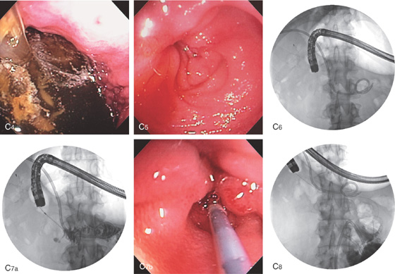
C4, The stomach is filled with fluid and debris. C5, In the proximal duodenum, a pinhole area is identified representing the point of obstruction, C6, Scout image shows the stent at the level of obstruction and the percutaneous placed biliary pigtail catheter. Note the markedly dilated stomach. C7a, C7b, After guidewire placement, the catheter is advanced to the level of obstruction. C8, Injection confirms the level of obstruction, as well as a normal-appearing distal duodenum.
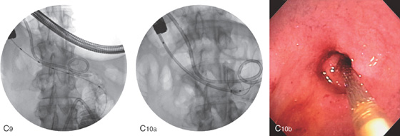
Figure 7.83 DUODENAL OBSTRUCTION FROM PANCREATIC CANCER
C9, A guidewire is passed distally followed by the catheter, and again injection is performed to confirm a normal distal bowel. C10a, C10b, The prosthesis is advanced over the wire fluoroscopically to the distal duodenum.
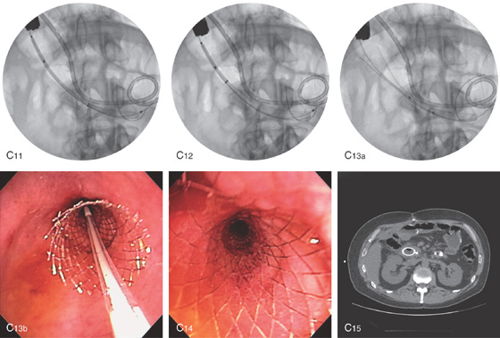
The stent is then slowly deployed (C11-C13b). C14, The stent has been fully deployed. C15, CT image following stent placement. The percutaneous catheter is still in place.
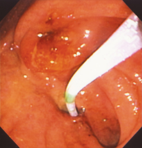
Figure 7.84 FISTULOUS OPENING INTO THE URETER
ERCP catheter in an opening inferior to the papilla that enters the ureter confirmed by injection of contrast.
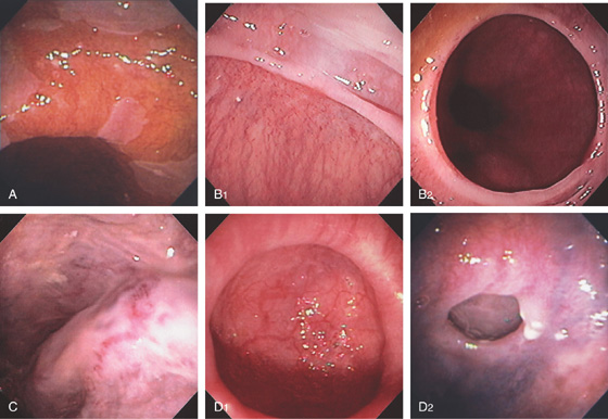
Figure 7.85 ENDOSCOPIC FINDINGS AT ERCP
At the time of ERCP, the side viewing endoscope can be used to examine the distal esophagus, stomach, and duodenum. The accuracy is quite high, and the opportunity should be utilized for a complete examination. A, Barrett’s esophagus. B1, B2, Nonobstructing Schatzki’s ring. C, Esophageal varices with red color signs. D1, D2, Epiphrenic diverticulum.
E, Cytomegalovirus (CMV) esophagitis. F, Squamous cell cancer of the esophagus. G1, G2, Gastric varices.
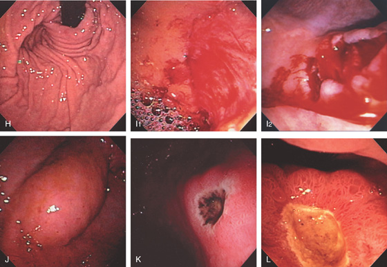
Figure 7.85 ENDOSCOPIC FINDINGS AT ERCP
H, Intact Nissen fundoplication. I1, I2, Proximal gastric tear on lesser curvature. J, Extrinsic compression from a dilated gallbladder in the antrum anteriorly. K, Antral ulcer with a black base. L, Duodenal ulcer (as shown from the pyloric canal).
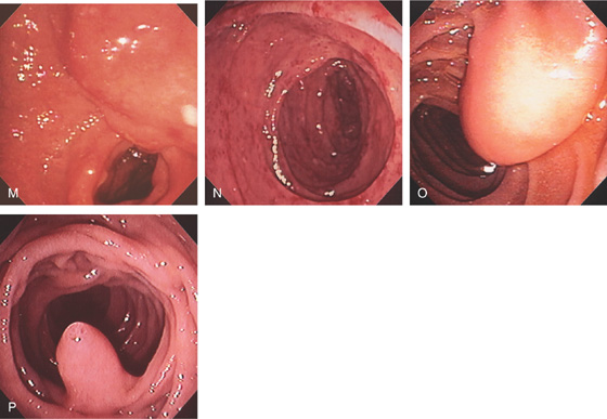
M, Extrinsic compression posteriorly in the duodenal bulb from cholangiocarcinoma. N, CMV duodenitis. O, Lipoma just distal to ampulla. P, Second ampulla.
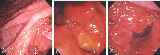
Figure 7.85 ENDOSCOPIC FINDINGS AT ERCP
Q, Scalloped duodenal folds in patient with celiac sprue. R, Ulcer underneath papilla caused by pancreatic cancer. S, Large, masslike lesion of the second duodenum resulting in obstruction.