CHAPTER 256 Gamma Knife Radiosurgery
Professor Lars Leksell first coupled an orthovoltage x-ray tube with his first-generation guiding device to focus radiation on the gasserian ganglion for the treatment of facial pain. He subsequently investigated cross-fired protons, as well as x-rays, from an early-generation linear accelerator for radiosurgery. In the 1960s, he became dissatisfied with the cumbersome nature of cross-fired proton beams and the poor reliability and wobble of then existing linear accelerators. Leksell and Larsson finally selected cobalt 60 as the ideal photon radiation source and developed the Gamma Knife.1 They placed 179 60Co sources in a hemispherical array so that all gamma rays (radiation from the decay of 60Co) focused to a single point, thereby producing cumulative radiation isocenters of variable volume depending on the beam’s diameter. The first Gamma Knife created a discoid-shaped lesion suitable for neurosurgical treatment of movement disorders and intractable pain.
Clinical work with the Gamma Knife began in 1967.2 In the early 1970s, a series of surgical pioneers at the Karolinska Hospital, Stockholm, began to use a re-engineered Gamma Knife (which created an oblate spheroidal isocenter) for the treatment of intracranial tumors and vascular malformations.3–6 Units 3 and 4 were placed in Buenos Aires and Sheffield, England, in the early 1980s. Lunsford and colleagues introduced the first clinical 201-source Gamma Knife unit to North America (the fifth gamma unit worldwide). Lunsford and associates first performed Gamma Knife radiosurgery in August 1987 at University of Pittsburgh Medical Center.7 In the United States, based on the available published literature, arteriovenous malformations (AVMs) and skull base tumors that failed other treatments were considered the initial indications for radiosurgery. A cautious approach was adopted while waiting for increased scientific documentation. The encouraging results of radiosurgery for benign tumors8 and vascular malformations9 led to an exponential rise in radiosurgery cases and sales of radiosurgical units (Tables 256-1 and 256-2). In recent years, metastatic brain tumors have become the most common indication for radiosurgery. Brain metastases now constitute 30% to 50% of radiosurgery cases at busy centers.10
TABLE 256-1 Numbers of Active Gamma Knife Units Worldwide by December 2006
| CONTINENT | COUNTRY | ACTIVE UNITS |
|---|---|---|
| Asia | China | 17 |
| Hong Kong | 1 | |
| India | 5 | |
| Japan | 51 | |
| Korea | 11 | |
| Philippines | 1 | |
| Singapore | 1 | |
| Taiwan | 6 | |
| Thailand | 1 | |
| Vietnam | 1 | |
| North America | Canada | 4 |
| Mexico | 2 | |
| United States | 115 | |
| Europe and Middle East | Austria | 2 |
| Belgium | 1 | |
| Croatia | 1 | |
| Czech Republic | 1 | |
| Egypt | 2 | |
| France | 3 | |
| Germany | 5 | |
| Greece | 1 | |
| Iran | 1 | |
| Italy | 5 | |
| Jordan | 1 | |
| The Netherlands | 1 | |
| Norway | 1 | |
| Romania | 1 | |
| Spain | 1 | |
| Sweden | 2 | |
| Switzerland | 1 | |
| Turkey | 3 | |
| United Kingdom | 3 | |
| Latin America | Argentina | 1 |
| Brazil | 1 | |
| Total units | 257 |
TABLE 256-2 Brain Disorders Treated Worldwide With Gamma Knife Radiosurgery by December 2006
| BRAIN DISORDER | INDICATIONS | NUMBER OF PATIENTS TREATED |
|---|---|---|
| Vascular disorders | Arteriovenous malformation | 48,407 |
| Aneurysm | 270 | |
| Cavernous malformation | 1,887 | |
| Other vascular disorders | 3,777 | |
| Benign tumors | Vestibular schwannoma | 36,843 |
| Trigeminal schwannoma | 2,312 | |
| Other schwannomas | 1,005 | |
| Meningioma | 49,558 | |
| Pituitary adenoma | 31,901 | |
| Pineal region tumor | 3,150 | |
| Craniopharyngioma | 3,397 | |
| Hemangioblastoma | 1,656 | |
| Hemangiopericytoma | 946 | |
| Chordoma | 1,619 | |
| Glomus tumor | 1,107 | |
| Other benign tumors | 3,490 | |
| Malignant tumors | Glial tumors (grades I-II) | 2,169 |
| Glial tumors (grades III-IV) | 23,610 | |
| Metastatic tumor | 141,210 | |
| Chondrosarcoma | 520 | |
| Nasopharyngeal carcinoma | 1,277 | |
| Other malignant tumors | 5,609 | |
| Functional targets | Trigeminal neuralgia | 25,198 |
| Parkinson’s disease | 1,309 | |
| Pain | 566 | |
| Epilepsy | 2,243 | |
| Obsessive-compulsive disorder | 140 | |
| Other functional targets | 867 | |
| Ocular disorders | Uveal melanoma | 1,354 |
| Glaucoma | 210 | |
| Other ocular disorders | 65 | |
| Total indications | 397,672 |
Evolution of the Gamma Knife
Models A, B, and C
The Gamma Knife has evolved steadily since 1967.11–13 In the first models (Model U or A), 201 cobalt sources were arranged in hemispherical array. However, these units present challenging cobalt 60 loading and reloading issues. To eliminate this problem, the unit was redesigned so that sources were arranged in a circular (O-ring) configuration (Models B, C, and 4C). Gamma Knife radiosurgery usually involves multiple isocenters with different beam diameters to achieve a treatment plan that conforms to the irregular three-dimensional (3D) volumes of most lesions. The total number of isocenters may vary depending on the size, shape, and location of the target. Each isocenter has a set of three x, y, and z stereotactic coordinates corresponding to its location in 3D space as defined with a rigidly fixed skull stereotactic frame. In terms of actual dose delivery, this means several changes in the patient’s head position within the helmet. In 1999 the Model C Gamma Knife was introduced. The first Model C in the United States was installed at the University of Pittsburgh Medical Center in March 2000. This technology combined advances in dose planning with robotic engineering and used a submillimeter-accuracy automated positioning system (APS). It obviated the need to manually adjust each set of coordinates in a multiple-isocenter plan. The robotic positioning system moved the patient’s head to the target coordinates defined in the treatment plan. The robot eliminated the time spent removing the patient from the helmet, setting the new coordinates for each isocenter, and repositioning the patient in the helmet. This advance significantly reduced the total time spent to complete the treatment and also increased accuracy and safety. Because treatment time was shortened, a precise 3D plan could be generated by using multiple smaller beams to enhance volumetric conformality. Such an approach results in a steeper dose falloff extending beyond the target (higher selectivity). Other features of the Model C unit included an integral helmet changer, dedicated helmet installation trolleys, and color-coded collimators.14–23 In 2005, the fourth-generation Leksell Gamma Knife (LGK) Model 4C was introduced. The first unit was installed at the University of Pittsburgh in January 2005. Model 4C was equipped with enhancements designed to improve workflow, increase accuracy, and provide integrated imaging capabilities. The integrated imaging, powered by Leksell GammaPlan (LGP), offered the ability to fuse images from multiple sources. These images can also be exported to a CD-ROM, so the referring physician could receive preoperative or postoperative images for reference and follow-up. The planning information could be viewed on both sides of the treatment couch. The helmet changer and robotic APS were faster and reduced total treatment time.
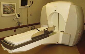
Leksell Gamma Knife PERFEXION
In 2002, Elekta Instrument AB, Stockholm, assembled a group of experts, including neurosurgeons, radiation oncologists, medical physicists, and engineers, who were assigned the task of defining specifications for the new LGK system. The group agreed on five critical features for the future system: (1) best dosimetry performance, (2) unlimited cranial reach, (3) best radiation protection for patient and staff, (4) full automation of the treatment process, and (5) patient and staff comfort. As a result of this development, a new system eventually called the LGK PERFEXION was officially introduced in 2006 (Fig. 256-1).24 The radiation unit was redesigned with beam geometry entirely different from that of the previous Gamma Knife Models U, B, C, and 4C. A total of 192 60Co sources were arranged in a cylindrical configuration in five concentric rings. This differed substantially from the previous hemispherical arrangements and resulted in a different source-to-focus distance for each ring that varied from 374 to 433 mm. The primary and secondary collimators were replaced by a single large 120-mm-thick tungsten collimator array ring (Fig. 256-2). Consequently, no external collimator helmets were needed for the PERFEXION system.
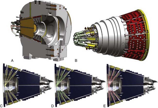
The range of collimators (beam size) was also changed from previous Gamma Knife models. Only three collimators are available for the PERFEXION system. The 4- and 8-mm collimators remain, but the 14- and 18-mm collimators were replaced with a 16-mm collimator. The tungsten collimator array is subdivided into eight identical but independent sectors, each containing 72 collimators (24 collimators for 4 mm, 24 collimators for 8 mm, and 24 collimators for 16 mm). Collimator size for each sector is changed automatically by moving 24 sources over the selected collimator set. A sector with 24 sources can be moved independently of other sectors to obtain five different positions: (1) home position when the system is standby, (2) 4-mm collimator, (3) 8-mm collimator, (4) 16-mm collimator, and (5) sector-off position, defined as a position between the 4- and 8-mm collimators that provides blocking of all 24 beams for the sector (see Fig. 256-2). Sector movement is performed by servo-controlled motors with linear scales located at the rear of the radiation unit.
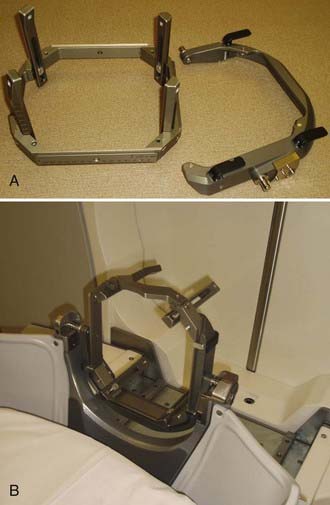
The APS responsible for setting the stereotactic coordinates was replaced by the bed patient positioning system (PPS). Instead of patient head movement in the Model C and 4C units, the whole patient couch now moves into preselected stereotactic coordinates in the PERFEXION model. This provides better patient comfort and facilitates completion of treatment in just a single run. Docking of the patient into the PPS is done by means of an adaptor that attaches to the standard stereotactic Leksell G frame with three clips. The adapter is then directly docked to the PPS (Fig. 256-3). The patient can be locked into three different neck positions, gamma angles of 70 (extension), 90 (neutral), or 110 (flexion) degrees. The gamma angle is the only treatment parameter that requires manual setup. The PPS replaces the APS and manual trunnion stereotactic coordinate setup and has repeatable accuracy in excess of 0.05 mm.
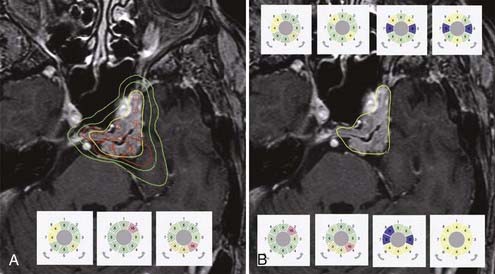
The entirely redesigned hardware of PERFEXION also has a significant impact on the treatment planning performed by the LGP PFX, which is a new version of the LGP running on a personal computer platform with a Linux operating system. In principle, there are three possible approaches for treatment planning: (1) the classic approach using a combination of 4-, 8-, and 16-mm isocenters (shots), as has been used for other models; (2) the use of composite shots containing a combination of 4-, 8-, and 16-mm or blocked sectors; and (3) the use of dynamic shaping, which automatically blocks selected sectors to protect volumes defined as critical structures (Fig. 256-4). The most revolutionary change in treatment planning is the ability to generate isocenters composed of different beam diameters. Such composite shots can optimize dose distribution shapes for each individual shot (see Fig. 256-4). The setup for any sectors, combination of different collimators, or blocking is free of time penalty because all sector position changes are done automatically and take less than 5 seconds.
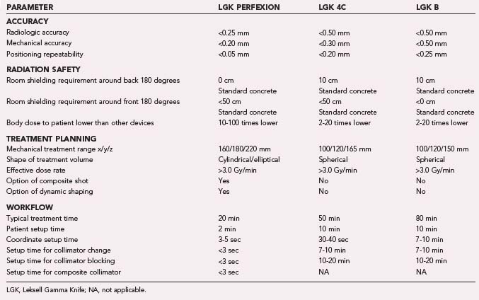
The new PERFEXION system provides better patient and staff shielding. Sectors are always in the off position (blocked) during patient transportation in the treatment position, transition into new stereotactic coordinates, pause, or emergency interrupt. This results in significantly (about 5 to 10 times) reduced extracranial radiation delivered to the patient in comparison to Models B and C. Because the PERFEXION system is fully automatic, it provides high efficiency during treatment, especially for multiple brain metastases. Our preliminary comparison study showed that when compared with other systems, an average 1.5 to 2.0 hours is saved in treating a patient with 10 brain lesions. The new LGK PERFEXION provides excellent dosimetry performance, unlimited cranial reach, enhanced radiation protection for the patient and staff, full automation of the treatment process, and better patient and staff comfort in comparison to previous models (Table 256-3). The PERFEXION system certainly has the potential to increase the spectrum of treatable indications, including multiple brain metastases, upper cervical spine lesions, and pathologies of the cranial base or head and neck. However, applications such as the upper cervical spine will require the development of a special fixation device and new dose-planning algorithm.
The Radiosurgical Procedure
The following are the basic steps for Gamma Knife radiosurgery with the LGK 4C and PERFEXION:
Application of the Stereotactic Guiding Device
Techniques of Stereotactic Imaging
Techniques of Conformal Dose Planning
Leksell Gamma Knife PERFEXION
Three different approaches to treatment planning can be applied when using the LGK PERFEXION. The first is to use the same strategy as described for the 4C system. Because just 4-, 8-, and 16-mm collimators are available, only a combination of these three different collimators can be used to cover the entire target volume. The second approach is to use dynamic shaping, a new feature in treatment planning introduced for the PERFEXION system. This automatic procedure will provide solutions to block selected sectors for protection of volumes defined as critical structures (see Fig. 256-4). Different levels to reduce the dose delivered to critical structures can be selected. The treatment planning system then automatically calculates which sectors should be blocked for each individual shot. One should be aware that each blocking will significantly increase total exposure time. The third approach is to use isocenters composed of different beam diameters, sectors, and blocked sectors. Any pattern of sectors, including 4-, 8-, and 16-mm collimators and blocks, can be generated. This can help significantly in shaping the dose distribution, especially for irregular volumes. For example, it is very easy to design an elongated dose distribution by using a combination of small and large collimators. Composite shots can also reduce the dose delivered to critical structures in close proximity to the treated target volume. Use of composite shots consisting of any sectors, a combination of different collimators, or blocking is free of time penalty because all sector position changes are done automatically and take less than 5 seconds.
Bradford CD, Morabito B, Shearer DR, et al. Radiation-induced epilation due to couch transit dose for the Leksell gamma knife model C. Int J Radiat Oncol Biol Phys. 2002;54:1134-1139.
Chiou TS. Patients treated by Model-C Gamma Knife with APS are less exposed to non-therapeutic irradiation. Minim Invasive Neurosurg. 2008;51:47-50.
Goetsch SJ. Risk analysis of Leksell Gamma Knife Model C with automatic positioning system. Int J Radiat Oncol Biol Phys. 2002;52:869-877.
Horstmann GA, Schopgens H, van Eck AT, et al. First clinical experience with the automatic positioning system and Leksell gamma knife Model C. Technical note. J Neurosurg. 2000;93(suppl 3):193-197.
Horstmann GA, Van Eck AT. Gamma knife model C with the automatic positioning system and its impact on the treatment of vestibular schwannomas. J Neurosurg. 2002;97(suppl):450-455.
Kondziolka D, Lunsford LD, Flickinger JC, et al. Emerging indications in stereotactic radiosurgery. Clin Neurosurg. 2005;52:229-233.
Kondziolka D, Maitz AH, Niranjan A, et al. An evaluation of the Model C gamma knife with automatic patient positioning. Neurosurgery. 2002;50:429-431.
Kuo JS, Yu C, Giannotta SL, et al. The Leksell gamma knife Model U versus Model C: a quantitative comparison of radiosurgical treatment parameters. Neurosurgery. 2004;55:168-172.
Leksell L. A note on the treatment of acoustic tumours. Acta Chir Scand. 1971;137:763-765.
Leksell L. Sterotaxic radiosurgery in trigeminal neuralgia. Acta Chir Scand. 1971;137:311-314.
Leksell L. Cerebral radiosurgery. I. Gammathalamotomy in two cases of intractable pain. Acta Chir Scand. 1968;134:585-595.
Leksell L. The stereotaxic method and radiosurgery of the brain. Acta Chir Scand. 1951;102:316-319.
Lindquist C, Paddick I. The Leksell Gamma Knife Perfexion and comparisons with its predecessors. Neurosurgery. 2007;61(3 suppl):130-140.
Lunsford LD, Flickinger J, Lindner G, et al. Stereotactic radiosurgery of the brain using the first United States 201 cobalt-60 source gamma knife. Neurosurgery. 1989;24:151-159.
Lunsford LD, Kondziolka D, Flickinger JC. Radiosurgery as an alternative to microsurgery of acoustic tumors. Clin Neurosurg. 1992;38:619-634.
Lunsford LD, Kondziolka D, Flickinger JC, et al. Stereotactic radiosurgery for arteriovenous malformations of the brain. J Neurosurg. 1991;75:512-524.
Niranjan A, Gobbel GT, Kondziolka D, et al. Heritage of radiosurgical research, current trends and future perspective. Prog Neurol Surg. 2007;20:359-374.
Niranjan A, Lunsford LD, Gobbel GT, et al. Brain tumor radiosurgery: current status and strategies to enhance the effect of radiosurgery. Brain Tumor Pathol. 2000;17:89-96.
Niranjan A, Maitz AH, Lunsford A, et al. Radiosurgery techniques and current devices. Prog Neurol Surg. 2007;20:50-67.
Regis J, Hayashi M, Porcheron D, et al. Impact of the model C and Automatic Positioning System on gamma knife radiosurgery: an evaluation in vestibular schwannomas. J Neurosurg. 2002;97(suppl):588-591.
Steiner L, Leksell L, Forster DM, et al. Stereotactic radiosurgery in intracranial arterio-venous malformations. Acta Neurochir (Wien). suppl 21. 1974:195-209.
Steiner L, Leksell L, Greitz T, et al. Stereotaxic radiosurgery for cerebral arteriovenous malformations. Report of a case. Acta Chir Scand. 1972;138:459-464.
Tlachacova D, Schmitt M, Novotny JJr, et al. A comparison of the gamma knife model C and the automatic positioning system with Leksell model B. J Neurosurg. 102 suppl. 2005:25-28.
Yu C, Jozsef G, Apuzzo ML, et al. Fetal radiation doses for model C gamma knife radiosurgery. Neurosurgery. 2003;52:687-693.
1 Leksell L. The stereotaxic method and radiosurgery of the brain. Acta Chir Scand. 1951;102:316-319.
2 Leksell L. Cerebral radiosurgery. I. Gammathalamotomy in two cases of intractable pain. Acta Chir Scand. 1968;134:585-595.
3 Steiner L, Leksell L, Forster DM, et al. Stereotactic radiosurgery in intracranial arterio-venous malformations. Acta Neurochir (Wien). suppl 21. 1974:195-209.
4 Steiner L, Leksell L, Greitz T, et al. Stereotaxic radiosurgery for cerebral arteriovenous malformations. Report of a case. Acta Chir Scand. 1972;138:459-464.
5 Leksell L. A note on the treatment of acoustic tumours. Acta Chir Scand. 1971;137:763-765.
6 Leksell L. Sterotaxic radiosurgery in trigeminal neuralgia. Acta Chir Scand. 1971;137:311-314.
7 Lunsford LD, Flickinger J, Lindner G, et al. Stereotactic radiosurgery of the brain using the first United States 201 cobalt-60 source gamma knife. Neurosurgery. 1989;24:151-159.
8 Lunsford LD, Kondziolka D, Flickinger JC. Radiosurgery as an alternative to microsurgery of acoustic tumors. Clin Neurosurg. 1992;38:619-634.
9 Lunsford LD, Kondziolka D, Flickinger JC, et al. Stereotactic radiosurgery for arteriovenous malformations of the brain. J Neurosurg. 1991;75:512-524.
10 Kondziolka D, Lunsford LD, Flickinger JC, et al. Emerging indications in stereotactic radiosurgery. Clin Neurosurg. 2005;52:229-233.
11 Niranjan A, Gobbel GT, Kondziolka D, et al. Heritage of radiosurgical research, current trends and future perspective. Prog Neurol Surg. 2007;20:359-374.
12 Niranjan A, Lunsford LD, Gobbel GT, et al. Brain tumor radiosurgery: current status and strategies to enhance the effect of radiosurgery. Brain Tumor Pathol. 2000;17:89-96.
13 Niranjan A, Maitz AH, Lunsford A, et al. Radiosurgery techniques and current devices. Prog Neurol Surg. 2007;20:50-67.
14 Bradford CD, Morabito B, Shearer DR, et al. Radiation-induced epilation due to couch transit dose for the Leksell gamma knife model C. Int J Radiat Oncol Biol Phys. 2002;54:1134-1139.
15 Chiou TS. Patients treated by Model-C Gamma Knife with APS are less exposed to non-therapeutic irradiation. Minim Invasive Neurosurg. 2008;51:47-50.
16 Goetsch SJ. Risk analysis of Leksell Gamma Knife Model C with automatic positioning system. Int J Radiat Oncol Biol Phys. 2002;52:869-877.
17 Horstmann GA, Schopgens H, van Eck AT, et al. First clinical experience with the automatic positioning system and Leksell gamma knife Model C. Technical note. J Neurosurg. 2000;93(suppl 3):193-197.
18 Horstmann GA, Van Eck AT. Gamma knife model C with the automatic positioning system and its impact on the treatment of vestibular schwannomas. J Neurosurg. 2002;97(suppl):450-455.
19 Kondziolka D, Maitz AH, Niranjan A, et al. An evaluation of the Model C gamma knife with automatic patient positioning. Neurosurgery. 2002;50:429-431.
20 Kuo JS, Yu C, Giannotta SL, et al. The Leksell gamma knife Model U versus Model C: a quantitative comparison of radiosurgical treatment parameters. Neurosurgery. 2004;55:168-172.
21 Regis J, Hayashi M, Porcheron D, et al. Impact of the model C and Automatic Positioning System on gamma knife radiosurgery: an evaluation in vestibular schwannomas. J Neurosurg. 2002;97(suppl):588-591.
22 Tlachacova D, Schmitt M, Novotny JJr, et al. A comparison of the gamma knife model C and the automatic positioning system with Leksell model B. J Neurosurg. 2005;102(suppl):25-28.
23 Yu C, Jozsef G, Apuzzo ML, et al. Fetal radiation doses for model C gamma knife radiosurgery. Neurosurgery. 2003;52:687-693.
24 Lindquist C, Paddick I. The Leksell Gamma Knife Perfexion and comparisons with its predecessors. Neurosurgery. 2007;61(3 suppl):130-140.