The cervical spine is the most mobile section of the whole spinal column; it is also the most vulnerable. This region is the richest in afferent proprioceptive nerves, which exercise an effect on the entire locomotor system. Dysfunctions here are therefore particularly important, and their treatment is correspondingly rewarding.
3.5.1. X-ray technique
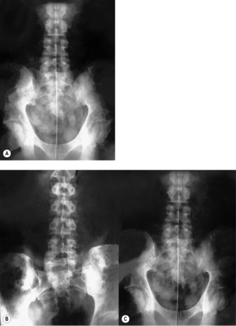
A suitable and effective technique is essential in order to obtain pictures that can be evaluated for function. The usual technique, which usually produces very poor visualization of the upper portion of the cervical spine in the lateral view and does not visualize it at all in the AP one, is not even adequate for morphological diagnosis and is completely useless for the evaluation of function.
The
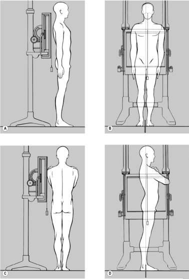
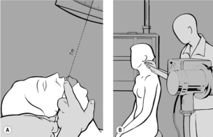
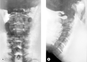
Sandberg–Gutmann technique (
Sandberg 1955) (see
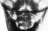
Figure 3.23 A) best meets the requirements for a successful image in the
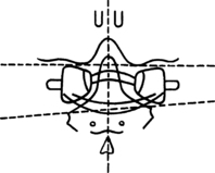
AP projection. For this, the patient is supine. Positioning is done using the following technique, so as to represent the patient’s posture accurately: the patient begins by sitting on the X-ray table, intergluteal cleft exactly on the midline of the table and legs extended, symmetrically side by side. Only then is the patient requested to lie down. Ask your patient to do so without use of the arms, looking straight ahead and in a completely natural manner. To check that the finding is representative rather than chance, this procedure may be repeated. If the head regularly deviates to one side, this must not be corrected; instead you should adjust the cassette and the X-ray tube accordingly. If you correct the head position you might either correct or artificially produce cervical scoliosis and at the same time induce axis rotation and lateral deviation of the atlas.
The film format used is either 18×24cm or 15×40cm; it can be helpful to include the upper thoracic spine as well. Position the cassette so as to be able to assess the upper margin of the foramen magnum, the front incisors and, caudally, at least T1. This is usually achieved when the upper edge of the cassette is aligned slightly craniad to the patient’s external ear.
Ask the patient to open her mouth as wide as possible and place a cork between her front teeth. The patient should then draw in her chin until the forehead (glabella) and upper lip (filtrum) are on the same horizontal plane. For this, a pillow beneath the head is often necessary, except when the patient is a child.
Now the X-ray tube can be centered. The central ray must be aligned through a point one finger’s breadth below the upper premolars to a point one finger’s breadth above the palpable inferior border of the occiput (posterior margin of the foramen magnum) in the midline. Either a light field indicator or a piece of string running from the center of the focal spot to the appropriate position on the patient’s face can be used for this alignment. The X-ray tube is then aligned so that the line of the central ray is an extension of that of the string (or light) (see
Figure 3.23 A). For edentulous patients, the central ray is aligned through a point one finger’s breadth below the maxilla to the border of the occipital squama, and in infants who do not yet have teeth, from the inferior border of the maxilla to the border of the occipital squama. Finally, correct any rotation of the patient’s head since this would make the film hard to evaluate.
This projection can also be taken with the patient seated, aligning the beam in an analogous manner. This approach is slightly more difficult but has the advantage of being performed under static conditions. Nevertheless, there can be an advantage in having taken the AP projection with the patient supine and the lateral one with the patient seated, if the findings reveal discrepancies. It is always possible then to perform an additional AP view taken in the sitting position.
One objection to the open-mouth technique is that the mandible is superimposed on the mid-cervical spine. This problem can be avoided if the patient rapidly opens and shuts her mouth while the film is being taken; in this way the shadow of the mandible is blurred. The risk in this case is that there will be slight associated movement of the head, which might cause blurring of the image at the craniocervical junction.
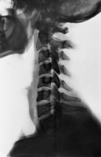
For the
lateral view the patient is seated relaxed in front of a vertical stand (see
Figure 3.23 B). The film may be 18
×24cm or 24×30cm, and must be placed so that the image demonstrates the cranial base as far as the sella turcica, and the cervical spine down to the cervicothoracic junction. In subjects with very tapering shoulders it will also be possible to include the first thoracic vertebra. The patient’s gaze should be fixed on a distant object at eye level, maintaining the hard palate horizontal. Take care that there is no inclination or rotation of the patient’s head, so that the two mandibles are exactly superimposed. This is necessary for accurate assessment of the film.Do not align the central ray on the mid-cervical region as is usually done, but on the tip of the mastoid process. The light field indicator can be used for this. It is best to use a film-focus distance of 1.5 meters or more. This produces an undistorted image of the cranial base and the entire cervical spine and also evens the exposure; the density of the cranial base means that it demands more irradiation than the cervical spine.
X-ray films of the cervical spine that do not provide good visualization of the atlanto-occipital and atlantoaxial joints and cranial base and of the cervicothoracic junction are inadequate for the evaluation of function.
3.5.2. Assessment of X-ray films
The position of the mastoid processes should also be symmetrical. In order to evaluate the inferior part of the cervical spine, it is necessary to ensure that the superior thoracic spine is not rotated.
In the
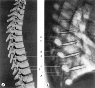
lateral projection (see
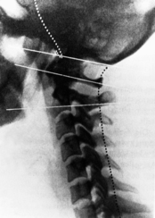
Figure 3.25), first ensure that the cranial base, including the sella turcica and hard palate, can all be seen. If possible the cervical spine should be shown as far down as C7, although this is often not possible in heavily built patients or those with high shoulders. Check that the alignment is perfect before beginning to evaluate the findings on the film. It is particularly important that the line of the hard palate should be horizontal.
Fineman et al (1963) showed that a difference of only 10° in inclination of the head is sufficient to change lordotic to linear posture, or even to change it to the extent that lordosis becomes kyphosis. It is important that the two halves of the mandible should overlie each other exactly. If the vertical borders of the rami appear projected side by side, the head is rotated to one side. Projection of the horizontal line of the mandible one above the other indicates that the head is inclined to one side. Another sign of rotation is if the shoulders are projected apart.
The
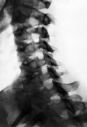
oblique projection (for which the patient adopts a position turned at an angle of 45°) gives the clearest imaging of the intervertebral foramina. This projection is indicated especially for radicular syndromes and vertebral artery syndrome. As recommended by
Gutmann (1956), this projection should be taken with the patient’s head in retroflexion, because this more clearly displays any narrowing of the intervertebral foramen. It is also recommended to take it not with the patient’s back to the cassette, but with the patient facing toward it (see
Figure 3.26).
3.5.3. Functional anatomy of the cervical spine
The cervical spine has two distinct sections: the atlanto-occipital and atlantoaxial joints, and the rest of the cervical spine from C3 to C7; nevertheless it is a functional unity, since all the movements it performs originate at the atlanto-occipital and atlantoaxial joints, these movements being anticipated by eye movements. The anatomical description will accordingly be treated in separate sections. The function of the cervical spine will then be dealt with as a whole.
Functional anatomy of C3–C7
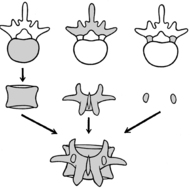
As in other parts of the spinal column, the degree of mobility in the cervical spine corresponds to the thickness of the intervertebral disk, which is greatest in the segments C3/C4 and C4/C5. The characteristic feature of the cervical spine is the raised lateral margins of the vertebral bodies, the uncinate processes. The disk therefore thins laterally, with the consequence that thinning of the disk brings about contact in this lateral region. This is where early degenerative changes occur, tending to form uncovertebral joints (neoarthroses). The position of these is very close to the intervertebral foramen. The significance for cervical function is that the shape of the vertebrae with their lateral margins limits side-bending and favors ante- and retroflexion.
The
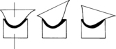
intervertebral joints are almost parallel, inclined at an angle of about 45° from ventrocranial to dorsocaudal. The angle is greatest at C2/C3. In this segment the joints are frequently not parallel but arranged as if on the circumference of a cylinder with its center behind the vertebra; it is therefore not pathological if the joint space at C2/C3 is less clearly delineated than in the other segments of the cervical spine in the lateral projection. As a general principle, laterally the joints in the lordotic section of the cervical spine are inclined slightly posteriorly and in the kyphotic section slightly anteriorly. According to
Janda (2002) the transition from the one to the other occurs roughly at C3/C4. The inclination of the intervertebral joints in the sagittal plane means that side-bending produces rotation, the two kinds of movement being coupled. Similarly, rotation brings about side-bending, always to the same side (see
Figure 3.30 A and B).
During
anteflexion, a slight ventral shift of the cranial partner vertebra relative to its caudal neighbor is often observed. In retroflexion there is a slight caudad shift. This too is associated with the inclination of the joints.
Penning (1968) describes this motion as a rotation of the upper vertebra relative to the lower one, around a frontal axis in the dorsal part of the vertebral body. Experience shows this motion to be physiological, as long as it occurs evenly in the motion segments of the cervical spine. It is regularly seen in young subjects with good mobility. If it is not observed in less mobile, older patients, this absence is not pathological. The shift is greatest between C2/C3 (see
Figure 3.32 B and D) where the range of motion is least in adulthood.
It is also important to note that the cervical spinal canal lengthens considerably during anteflexion, shortening during retroflexion. This produces a significant movement of the meninges and dural sheaths of the nerve roots relative to the spinal cord, which becomes longer and thinner in anteflexion and shorter and thicker in retroflexion.
The course of the vertebral artery also has an important role. This enters its bony canal at C6, passing upward through the intervertebral foramina in close contact with the intervertebral joints and uncinate processes almost at right angles to the course of the nerve roots. Therefore, as the intervertebral foramen (canal) narrows in retroflexion, this may affect both the nerve root and the vertebral artery.
Functional anatomy of the craniocervical junction
The
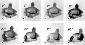
atlantoaxial joint is made up of the articulation between the anterior arch of the atlas and the dens of the axis, between the dens and the transverse ligament of the atlas with its articular cartilage, and between the lateral mass of the atlas and the body of the axis. Its main function is that of rotation, and it also performs ante- and retroflexion. All these articulations participate in rotation. On one side the lateral mass of the atlas glides ventrally on the body of the axis, rising as it does so, while on the other side the lateral mass of the atlas glides dorsally and downward. The rotation is limited by the joint capsules and the strong alar ligaments, which have their attachment to the margins of the foramen magnum. The average range of motion of this rotation (our own results) is 25° in each direction, although we have found a range of motion up to as much as 40° (see
Figure 3.28). Dvorák, using CT, even obtained average measurements of 41.1° to the right and 44° to the left. Huguenin, on the other hand, in measurements made using CT, obtained figures corresponding to our own.
Ante- and retroflexion between atlas and axis is considerable, amounting on average to 15°. The anterior arch of the atlas slides up and down on the dens of the axis, while the atlas itself performs a tipping motion (see
Figure 3.29).
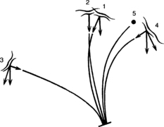
Kinematics of the cervical spine
Side-bending
Side-bending can be studied only by X-ray, hence the decision to deal with it under functional radiographic studies (see
Figure 3.30). Like rotation, it begins at the atlanto-occipital and atlantoaxial joints. This can be demonstrated by looking at the craniocervical region in passive side-bending (‘side-nodding’). This shows that side-bending starts with rotation of the axis relative to the atlas. At the same time we find a synkinesis in which the atlas shifts relative to the occipital condyles and C2 in the direction of the side-bending (see
Figure 3.30 C).
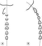
During this side-bending the cervical spine rotates, maximum rotation occurring at C2.
Jirout (1968) demonstrated that this
rotation is absent in the lower cervical spine during side-bending to the right, but during side-bending to the left it continues down into the upper thoracic spine. He explains this as being due to the stronger pull of the muscles of the shoulder girdle on the right side, whose attachment to the spinous processes exerts a pull to the right and so brings about left rotation. This combination of side-bending and rotation is consistent with the positioning of the intervertebral joints, although this cannot be the true cause, as is usually thought, because the side-bending originates at the axis. This rotates even with the slightest side-bending, followed by the other segments. If rotation of the axis does not take place, there is no rotation of the rest of the cervical spine (see
Figure 3.47 B).
According to
Jirout (1968), the forces that bring about
axis rotation are the product of side-bending of the head (see
Figure 3.31). Side-bending of the head involves rotation of the head about a sagittal axis at the level of the root of the nose. This creates a pull on the spinous process of the axis, which causes rotation of the axis with simultaneous tipping in the sagittal direction. This tipping motion in the sagittal plane, which takes place both in side-bending and in rotation, is, according to
Jirout (1968), the joint play of the cervical spine. The sideways shift of the spinous process can easily be palpated, and occurs as soon as the subject’s head inclines to the side even to a slight degree. Interestingly,
Gaymans (1973) demonstrated that a shifting of the spinous process of the axis (rotation of the axis) occurs even on mere leaning against slight resistance in the neutral position and with minimum pressure, thus simply through the pull of the muscles. He obtained radiological evidence of this.
Rotation of the axis on side-bending of the cervical spine is not simply the combined result of rotation movements of the individual vertebrae, due to the inclination of the zygapophysial joints of C7, C6, etc.; on the contrary it results from the inclination of the head itself, in which the head rotates about a sagittal axis and exerts a pull on C2. If there is no rotation of the axis, there is also no rotation of the other vertebrae of the cervical spine during side-bending. At the same time there is a tipping motion in the sagittal plane, so that the movement occurs in a coupled way in all three planes.
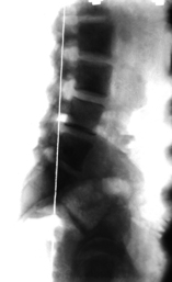
Anteflexion and retroflexion
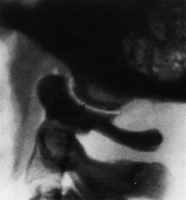
Two distinct kinds of anteflexion should be distinguished. The first is a nodding movement limited to the atlanto-occipital and atlantoaxial joints. The other is a forward flexion involving the entire cervical spine. This distinction does not exist for retroflexion. The two kinds of anteflexion of the head are to some extent mutually exclusive. If we draw the chin in toward the chest (forward nodding), this usually inhibits full anteflexion. If we drop the head far forward in anteflexion, this renders nodding more difficult except in hypermobile subjects. The explanation lies in the tipping mechanism of the atlas.
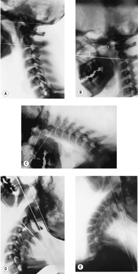
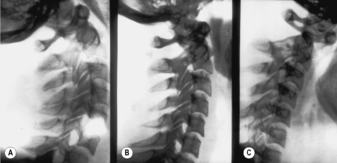
The following changes can be observed in X-ray studies of anteflexion and retroflexion (see
Figure 3.32):
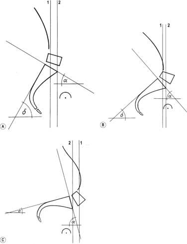
• In the
erect posture (see
Figure 3.32 A), the atlas is already in a position of slight retroflexion with an average angle of about 5°.
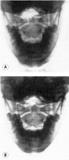
• During
forward nodding (see
Figure 3.32 B), anteflexion of the atlas increases only slightly. This movement causes an anteflexion of the head (the plane of the foramen magnum); in the erect posture the head had been in a position of anteflexion relative to the atlas. In this position the atlanto-occipital and atlantoaxial joints are in maximum anteflexion.
• In
maximum anteflexion (see
Figure 3.32 C), the cervical spine is almost horizontal; there is a proportional slight ventral shift of the individual cervical vertebrae up to C2. Anteflexion between C1 and C2 is at its maximum. In contrast to the situation in the erect posture and in forward nodding there is now retroflexion of the head relative to the atlas, which can be greater than in retroflexion with the subject seated. Anteflexion of the atlanto-occipital and atlantoaxial joints is thus reduced as compared to forward nodding, closer to the degree of anteflexion in the erect posture. Consequently the angle between the clivus and dens is usually the same with the head erect as during maximum anteflexion. There is also a forward shift of the clivus (basion), together with the atlas, relative to the tip of the dens.
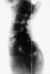
• In
maximum retroflexion with the subject seated (see
Figure 3.32 D), there is maximum retroflexion of the atlas (relative to the axis). Retroflexion of the cranium, on the other hand, is seldom at its maximum (it is usually very little greater than during anteflexion of the head). Here, too, we see a proportional dorsal shift of the individual cervical vertebrae from C7 to C2 and of the clivus and atlas relative to the tip of the dens.
• In
passive retroflexion with the subject side-lying and so without the effect of gravity (see
Figure 3.32 E), there is now maximum retroflexion of the head relative to the atlas, while retroflexion of the atlas relative to C2 is even less than in the erect posture. There is no dorsal shift of the basion with the atlas.
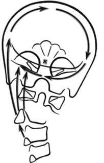
The mechanism underlying these processes, which appear paradoxical at first sight, has been termed the tipping of the atlas. It is based on the following (see Figure 3.33): in anteflexion with the subject sitting, as soon as the center of gravity of the head shifts ventrally, the occipital condyles exert pressure on the anterior, rising part of the concave articular surface of the atlas. This causes the atlas to tip forward and downward. There is an analogous process in retroflexion with the subject sitting: the atlas tips backward. This does not happen, however, with the subject lying on one side, which explains why in this case retroflexion of the occiput relative to the atlas attains its maximum.
3.5.4. X-ray anatomy of the cervical spine
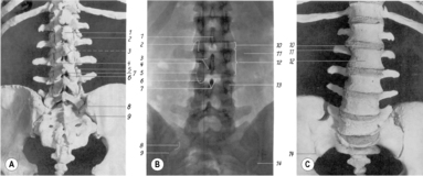
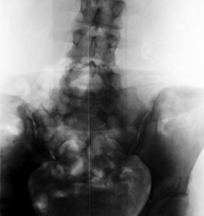
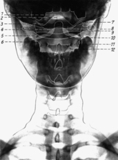
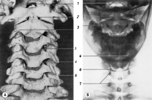
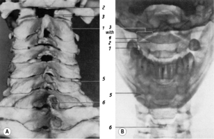
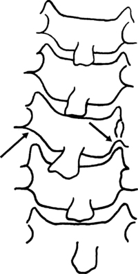
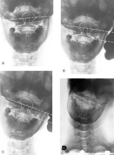
Anteroposterior view
The inferior contour of the lateral mass forms the superior articular surface of the joint between C1 and C2. At the medial border of the joint facet of the axis there is a tiny notch marking the border of the dens. The tip of the dens usually lies well below the superior border of the foramen magnum. Just below the lateral end of the superior joint facets of the axis is the foramen transversarium. Medial to this foramen, the point-like projection of the pedicles of the axis can be seen. From here can be traced the shadow of the arch of the axis on both sides, through to the spinous process. If there is hyperlordosis it is sometimes possible to see into the spinal canal above the arch of the axis.
Below the axis can be seen the typical cervical vertebrae with their characteristic uncinate process either side. This causes the intervertebral disk to be much higher medially than laterally. Beneath the unciform processes lies the shadow of the point-like pedicles. The spinous processes can be seen in the midline and the lateral contour is formed by the transverse processes. The intervertebral foramen is visible, but less clearly. Rarely, the intervertebral joint space can be seen.
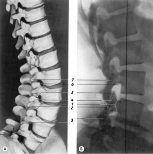
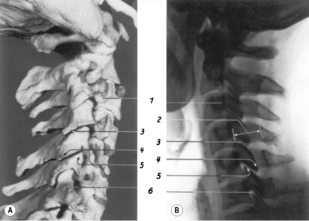
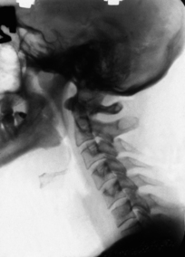
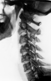
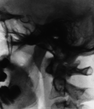
Lateral view
The lateral view (see
Figure 3.36) offers an undistorted image of the cranial base and the atlanto-occipital and atlantoaxial joints. The clivus can be followed in its entirety down from the sella turcica to the anterior margin of the foramen magnum (basion) which is situated directly above the tip of the dens. The posterior margin of the foramen magnum (opisthion) cannot always be clearly distinguished from the squama of the occipital bone; it helps to follow the posterior margin of the cervical spinal canal from caudad to craniad. Where the arc-shaped prolongation of this margin meets the occiput is the opisthion.
The mastoid process frequently overlaps the condyle and atlanto-occipital joint; therefore this joint is not always visualized in the lateral view, although it is often clearly seen (see
Figure 3.37).
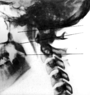
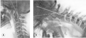
The
plane of the foramen magnum can be established by drawing a line from the basion to the opisthion on the posterior margin of the foramen magnum. The plane of the atlas corresponds to a straight line through the middle of the anterior and posterior arches of the atlas. The plane of the axis lies on a straight line linking the inferior border of the transverse processes and the inferior border of the spinous process. These lines are used to determine the ante- or retroflexion of the occiput, atlas, and axis (see
Figure 3.25 and
Figure 3.38).
The dens of the axis is projected just behind the anterior arch of the atlas. The tip of the dens is usually at the same level as the superior border of the anterior arch of the atlas. It should not be much above the palato-occipital line; this is the case in basilar impression.
In this section of the spinal column, unlike the others, the pedicles and transverse processes are projected onto the vertebral bodies in the lateral view but not in the AP view, because here the spinal canal is wider than the vertebral bodies. The superior border of the transverse processes lies slightly above the superior end-plate of the vertebral bodies, which can cause them to appear somewhat blurred. In the lower cervical spine the shadow of the transverse processes lies more in the dorsal direction and in the superior cervical spine more ventrally; at C2 the position of this shadow of the transverse process is such that its anterior border overlies the anterior border of the vertebral body.
The shadows of the articular processes and joint spaces are projected behind the vertebral bodies. If the projection is well executed, all that can be seen is a lucency, showing that the joints are essentially parallel. This need not be so at C2/C3, where it can be quite normal to see some fuzziness of outline. The posterior margin of the spinal canal corresponds to a line linking the bases of the spinous processes (posterior border of the vertebral arch) – a rule that thus also applies to the atlas, which does not have a spinous process. If, however, this shadow is absent at the atlas, this is a sign of spina bifida atlantis, a frequently-found anomaly.
3.5.5. Evaluation with respect to functional implications
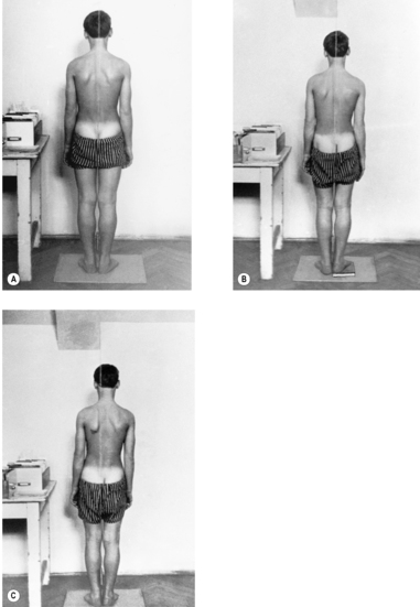
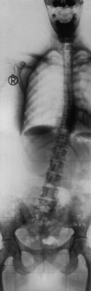
The most characteristic disturbance of statics in the cervical region is the
forward-drawn posture (see
Figure 3.39). Even when statics are normal, the centre of gravity of the head is slightly in front of its support, so that electromyographic studies reveal a slight degree of muscular activity in the nuchal muscles even with the subject in normal erect posture. As soon as there is any forward inclination (not flexion!), whether of the entire body or of the neck alone, tension can immediately be palpated in the muscles of the back of the neck. The forward-drawn position therefore creates overload of the cervical spine and compensatory hyperlordosis at the atlanto-occipital and atlantoaxial joints, and tension in the short extensor muscles of the neck.
In order to demonstrate the patient’s
natural posture radiographically, lateral projections should be taken with the subject seated in a relaxed manner, in a backless chair, as described by
Gaizler (1973). It is important to ensure that the patient remains relaxed, with gaze fixed on an object at eye level, so that there is no anteflexion of the head despite the natural posture. We took projections of a group of 50 patients with the patients in erect posture (kneeling), and sitting both upright and relaxed. Whereas with the subject sitting upright the external auditory meatus was projected almost exactly above the anterior border of C7, in the erect posture it was 7
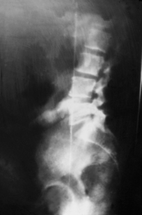
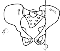
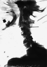
mm in front of C7, and sitting relaxed it was projected forward by 16mm; in individual cases even by 5cm. This was particularly the case where a patient’s relaxed sitting position involved lumbar kyphosis.Other frequent findings are the
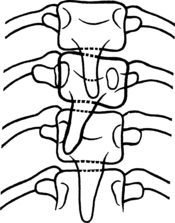
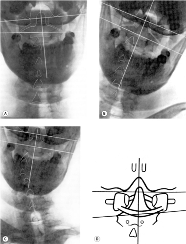
rotation of several vertebrae (see
Figure 3.46) and, in the region of the atlanto-occipital and atlantoaxial joints, lateral shifting, an asymmetrical position of the condyles relative to the atlas, and of the atlas in relation to the axis. This is often described as a shift of the atlas to one side relative to the condyles
and to the axis, which is not quite appropriate: the description should always be given in terms of the upper element relative to the lower. The description in this case would not be of the atlas to the right relative to the condyles and axis, but of the atlas to the right relative to the axis, and the condyles to the left relative to the atlas (see
Figure 3.41,
Figure 3.42 and
Figure 3.43).
Isolated rotation of the atlas in relation to both the occiput and the axis is fairly uncommon. The joint space between atlas and axis is narrower on the side of rotation, the lateral triangle of the lateral mass becomes larger, the center of the posterior arch is shifted in the opposite direction to the rotation, and the lateral mass becomes larger on the side opposite to rotation.
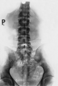
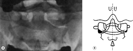
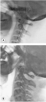
Much more frequent than rotation of the atlas is
axis rotation in neutral posture (see
Figure 3.44). A 5° or occasionally even 10° rotation of the axis is not unusual. Interestingly, the rotation of the axis is caudally transmitted, down to the rest of the cervical vertebrae and even down as far as the cervicothoracic junction, particularly when rotation is to the left. This can happen even in the simple case of lateral deviation of the spinous process. The mechanism clearly seems to be the same as that discussed in connection with side-bending, which brings about left rotation of the lower cervical spine and cervicothoracic junction.
The characteristic features of axis rotation in the AP view are the deviation and position of the pedicles and the spinous process to that of rotation. The foramen transversarium widens on the side of rotation and the joint space narrows on the opposite side.
Rotation of the other cervical vertebrae is characterized not only by the deviation of the spinous process and rotation of the pedicles to the opposite side, but also by distortion of the unciform processes (see
Figure 3.45). In the lateral view, the structures that usually overlap are projected apart. This applies particularly to the joint spaces, together with the articular processes and transverse processes. At C2 one transverse process is projected in front of the vertebral body (see
Figure 3.46).
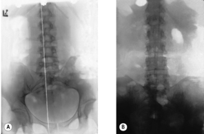
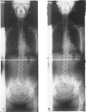
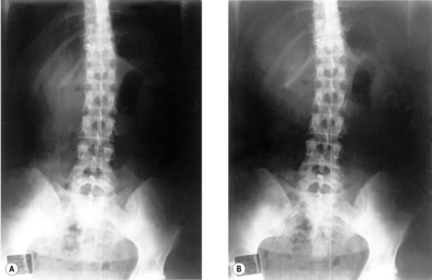
An important sign of static disturbance is discrepancy between the AP view taken with the patient supine and the lateral view with the patient sitting, in particular if there is rotation in the view taken sitting and none at all in the AP view with the patient supine. The cause may be an oblique plane below the cervical spine.
3.5.6. Movement studies
Radiographic movement studies are used to investigate
restrictions and
hypermobility. X-rays are taken in ante- and retroflexion and side-bending. Rotation is less studied by this method because interpretation is difficult.
Although lateral shifting of the atlas occurs in side-bending, this shifting can sometimes be absent without implying any movement restriction, especially if there is marked asymmetry. More importantly, the shifting may still be seen in the radiographic image even in cases where there is restriction. If there is restriction blocking axis rotation, no side-bending occurs at the atlanto-occipital and atlantoaxial joints (see
Figure 3.49). This is in keeping with the fact that in cases of atlas assimilation, side-bending at the craniocervical junction occurs in the normal way.
This raises the question as to whether
restriction between occiput and atlas on side-bending can be demonstrated radiographically at all. We have shown this to be possible (
Lewit & Krausová 1967) with the head rotated to the side, locking the atlas/axis motion segment. This is necessary to obtain an accurate diagnosis.
It is not usually difficult to demonstrate a restriction of side-bending between the atlas and axis. When this is done, rotation is (also) seen to be blocked (see
Figure 3.47 and
Figure 3.49). The radiological evidence of restriction in the other motion segments of the cervical spine is much more difficult to achieve. According to
Jirout (1971) side-bending is accompanied by slight synkineses in the sagittal plane, consisting of ante- and retroflexion movements that can be recognized by a change in the position of the spinous processes relative to the vertebral bodies. Comparison of the films taken before and after manipulation found a more marked reaction of these synkineses in restrictions than actual side-bending as seen radiographically.
To summarize:
• Lateroflexion of the head against the cervical spine (side-bending; ‘side-nodding’) is mainly performed by means of rotation of the axis relative to the atlas. Normalization of side-bending at the atlanto-occipital and atlantoaxial joints also normalizes this rotation.
• Lateroflexion between occiput and atlas can be established radiographically and clinically only if the more mobile segment (C1/C2) is locked, that is if the head and atlas are rotated by at least 45°. The movement restriction between occiput and atlas does not affect side-bending in the frontal plane or the synkinesis between occiput and atlas during side-bending in the sense of a lateral shift accompanied by simultaneous rotation of the axis.
• Ante- and retroflexion is the movement most frequently examined by X-ray. The disadvantage of this examination from the point of view of manipulation therapy is that this is the movement most frequently and preferentially performed and so the least susceptible to dysfunction. Hypermobility, on the other hand, is more readily revealed here. This can reveal increased shift between neighboring vertebrae, increased lordosis or kyphosis between neighboring vertebrae, and the following signs of hypermobility at the craniocervical junction:
– Laxity of the transverse ligament of the atlas and a widening of the joint space between the anterior arch of the atlas
and the dens of the axis, especially the superior part (see Figure 3.50). As a consequence the basion also shifts anteriorly. During anteflexion the distance between the anterior arch of the atlas and the dens and the angle between the clivus and the dens decreases. This happens not only on forward-nodding, but also anteflexion (see
Figure 3.51).
– Hypermobility between the occipital condyles and the atlas without laxity of the transverse ligament of the atlas can be recognized by a shift of the basion and opisthion in relation to the dens of the axis (see
Figure 3.52).
3.5.7. Morphological changes
It is not the task of this book to deal in detail with morphological and structural changes; nor is it necessary to do so, since this field forms the subject of textbooks of radiology and orthopedics. Therefore only certain aspects, the limited number of those that are particularly important from the point of view of manual medicine, are touched on here.
Anomalies
Block vertebrae
Block vertebrae lead to a compensatory hypermobility in the neighboring segments. The coalescence may be complete or partial, or sometimes simply consist of a hypoplastic intervertebral disk, in which case the vertebral bodies adjacent to the hypoplastic disk are narrower (see
Figure 3.53). This occurs because the adjacent end-plates – between which the hypoplastic disk lies – are also the zone of growth. This anomaly could easily be confused with the consequences of childhood rheumatoid arthritis (Still’s disease). The difference lies in the obliteration of the joints, while the vertebral arches and spinous processes are normally developed.
Cervicothoracic transitional vertebra
A transitional C7 cervicothoracic vertebra with a very large transverse process or with a cervical rib is another frequent anomaly. There may also be an absence of the unciform process on one or both sides. A transitional T1 vertebra is however rare.
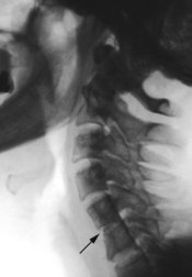
Spinal canal stenosis
A narrow spinal canal is particularly important clinically, because it is the most important cause of cervical myelopathy. From the practical point of view in diagnosis it is more helpful to look at the change in the proportions of the individual anatomical structures than to measure the sagittal diameter of the spinal canal; the proportions of the structures can be seen at first glance. Normally, in the cervical spine, the spinal canal is wider than the vertebral bodies. In spinal canal stenosis this is not so; also (if there is no rotation in the radiograph) the articular processes overlie the entire width of the spinal canal (see
Figure 3.54).
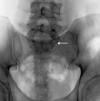
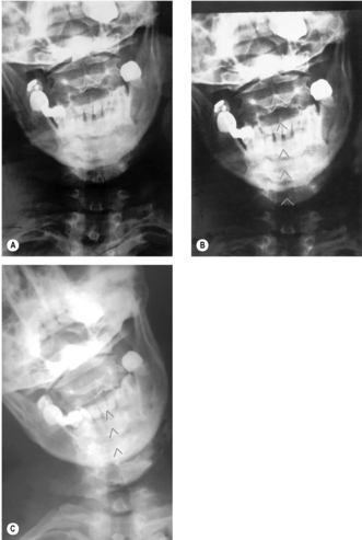
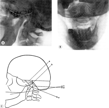
Basilar impression
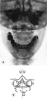
As a region of transition, the craniocervical junction, the region of the atlanto-occipital and atlantoaxial joints, is the site of many anomalies. Probably the most important of these is basilar impression (see
Figure 3.55), which is the result of hypoplasia of the basiocciput. In this condition the occipital part of the clivus is shortened and therefore the dens axis appears as if shifted into the foramen magnum, so as to lie above the palato-occipital line in the lateral view (see
Figure 3.55 A). In the AP view the dens can be above the occipital condyles, placing it well above the line between the mastoid processes and digastric muscles (see
Figure 3.55 B). At the same time the foramen magnum may be narrower than usual, unless there is also an Arnold–Chiari malformation, in which case displacement of the tonsils of the cerebellum below the foramen magnum has the effect of widening it. These changes can cause syndromes associated with compression of the medulla oblongata, similar to those of spinal canal stenosis in the cervical region.
All the anomalies listed here are frequently asymmetrical, so that lateral displacement of the atlas and also rotated positions of the axis can be found simultaneously. In addition there can also be hyperlordosis. It is therefore little wonder that these anomalies often also lead to dysfunctions which in turn cause pain.
Hypoplasia of the dens of the axis
Hypoplasia of the dens or especially the os odontoideum leads to pathological instability (see
Figure 3.56). Another anomaly deserving of mention is reclination of the dens (Gutmann 1981), which results in retroflexion of the atlas and therefore places increased strain on the transverse ligament of the atlas during head anteflexion.
Degenerative changes
Degenerative changes can be of clinical significance, especially if they affect the intervertebral foramen, if they are closely associated with the nerve root and the vertebral artery, or if they cause additional narrowing of an already narrow spinal canal. These changes mainly develop in the region of the uncinate processes when there is thinning of the disk, bringing the uncinate processes into close contact with the body of the vertebra above. This can lead to the formation of uncovertebral joints (neoarthroses) and osteophytes.
Degeneration of the articular processes also has an effect on the intervertebral foramina.
Arthroses of the zygapophysial joints often occur as a consequence of their horizontal position, whether this has come about as an anomaly or in the case of hyperlordosis. In such cases the joint facets, rather than the end-plates of the vertebral bodies, become the weight-bearing structures. This causes a broadening and condensation of these joints, and they can therefore be clearly seen in the AP view (see
Figure 3.57) as well as the lateral view.
Finally, the significance of a
divergent course of the paired joints in the cervical spine needs to be highlighted. This change can clearly be seen in a well-centered lateral view. It causes rotation of the upper of two neighboring vertebrae, relative to the caudally adjacent one, during retroflexion, and consequent narrowing of the intervertebral foramen on the side of the rotation (see
Figure 3.58).