[level-membership-for-anesthesiology-category]
Chapter 7 Equipment for the inhalation of oxygen and other gasses
Introduction
The benefits of supplemental oxygen are:
• as a treatment for hypoxaemia due to hypoventilation, or due to gas transfer or ventilation/perfusion abnormalities (e.g. heart failure, anaesthesia)
• to improve oxygen supply to tissues, when a disease process causes oxygen demand to outstrip delivery (e.g. severe sepsis, malignant hyperpyrexia)
• as a specific treatment for certain conditions, e.g. carbon monoxide poisoning, postoperative nausea and vomiting
• to allow humans to survive at very low atmospheric pressure, e.g. mountaineering and high altitude flying.
Normobaric oxygen therapy
There are almost as many devices that deliver oxygen as there are indications for its use. These devices may be classified by the extent to which the patient relies upon them to correct any deficiency in oxygen delivery (Table 7.1).
Table 7.1 A classification of oxygen delivery devices by degrees of dependency
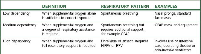
CPAP, continuous positive airway pressure; NIPPV, non-invasive positive pressure ventilation; IPPV, intermittent positive pressure ventilation
Low dependency systems
Variable performance devices
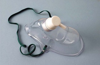
With these devices, the oxygen concentration delivered to the upper airway varies with the phase and pattern of respiration (as well as the selected oxygen flow rate). As an example, consider a standard oxygen mask applied to the face (Fig. 7.1). Oxygen flows into the facemask from a continuous supply and quickly fills the relatively small volume of the mask (approximately 200 ml) at the end of an exhaled breath. The oxygen then begins to escape through the mask’s vents and where the seal against the face is imperfect.
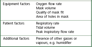
The complex interplay between the factors that determine FIO2 (Table 7.2) means that most oxygen delivery devices deliver a variable FIO2. The extent of this variability is difficult to quantify as normal methods of measuring breathing pattern are impractical in clinical practice. The latter require a mouthpiece that interferes with oxygen flow in the mask, and subjects are not able to breathe with a fixed respiratory pattern long enough for accurate measurements to be recorded. These difficulties explain why the factors most influential in determining FIO2 are still unclear.
No capacity oxygen delivery devices
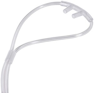
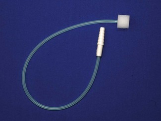
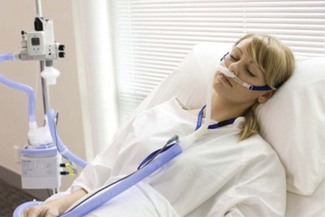
Traditionally, nasal cannulae (also known as nasal prongs or specs) deliver unhumidified oxygen to the nasopharynx (Fig. 7.2). They are more comfortable and less claustrophobic than facemasks, allowing talking, eating and drinking, and making them the most suitable means of delivering long-term oxygen therapy for chronic conditions, especially at home. The main drawback is that an unhumidified oxygen flow greater than 2 L min−1 can cause discomfort and drying of the nasal mucosa. Thus unhumidified oxygen therapy in association with the tiny capacity of the nasal cannulae leads to variable FIO2. Clinical and laboratory studies in this context have shown an enormous variability with respiratory pattern, FIO2 ranging between 0.26 and 0.90.2,3 A further design is the nasal sponge (tipped) catheter, which is lodged in one nostril and again effectively uses the nasopharynx as a small reservoir during the respiratory pause (Fig. 7.3). Devices permitting humidified oxygen therapy via nasal cannulae are now available (Fig. 7.4), allowing oxygen flow rates up to 60 L min−1 to be tolerated for long periods. As a result, consistently higher, more reliable FIO2 can be achieved with this form of high flow humidified oxygen therapy.4 However, warm humidified gas is a good medium for bacterial growth; therefore, it is mandatory that any disinfection and infection control procedures deemed necessary by manufacturers and regulatory authorities are adhered to. The other point to note is that delivering high flows into the nasopharynx generates a small amount of positive end expiratory pressure (PEEP) depending on the flow used and if the mouth is open or closed. Pharyngeal pressures of up to 4 cm H2O have been recorded with a flow of 60 L min−1 with the mouth open, increasing to nearly 10 cm H2O with the mouth closed.5 As such, high flow humidified oxygen therapy delivered via nasal cannulae should be regarded as a medium dependency device (see below). Its role in the management of acutely breathless patients is becoming increasingly appreciated.
Low capacity oxygen delivery devices (capacity <100 ml)
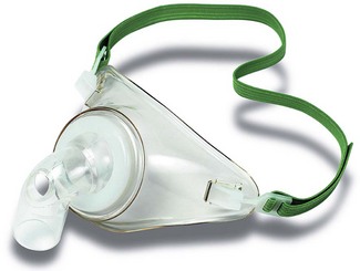
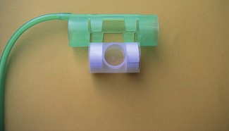
Facemasks for children, or tracheostomy masks (Fig. 7.5) have a volume of approximately 70–100 ml. Tracheostomy masks, especially, do not provide humidification without extra equipment, and so are best suited for short-term use. In long-term use, oxygen may be humidified by using a ‘Swedish nose’ device (Fig. 7.6) (see also Chapter 11, Humidifiers). This is a small, light heat and moisture exchanger that connects to the tracheostomy tube by means of a 15 mm International Organization for Standards (ISO) connector. Supplemental oxygen can be administered into this via a clip-on device. A ‘Swedish nose’ may also provide 2.5–5 cm H2O of PEEP.
Medium capacity oxygen delivery devices (capacity 100–250 ml)
Standard adult facemasks are designed to cover the nose and mouth and have a capacity of approximately 175–200 ml (Fig. 7.1); there are a multitude of different designs. They are, almost without exception, made of transparent soft plastic with an elastic strap to secure the mask in place. Some incorporate a short deformable metal bar allowing the mask to be shaped around the nose to achieve a closer fit. Oxygen flow rates of 2–15 l min−1 result in a highly variable and unpredictable FIO2. Rebreathing of CO2 can occur with O2 flow rates of less than 2 L O2 min−1 or if minute ventilation is very high.6 A more recent design (Intersurgical, UK) fits filters in the expiratory ports, in an attempt to reduce infection risk from aerosolized pathogens emitted from the patient’s airway.
High capacity oxygen delivery devices (capacity 250–2500 ml)
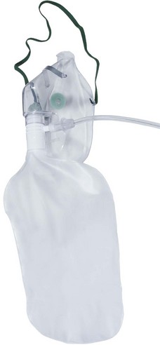
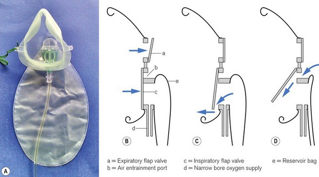
Air is only entrained into a facemask when the patient’s inspiratory flow rate exceeds the oxygen supply rate. To achieve a FIO2 near 1.0 (100% oxygen) by providing sufficient oxygen flow alone, rates in excess of 60 l min−1 would be required (in order to exceed the patient’s peak inspiratory flow rate) which is clearly impractical. Increasing mask size simply increases the risk of rebreathing CO2. However, a great deal of oxygen delivered to the facemask is lost to the atmosphere whenever the patient’s inspiratory flow rate is (a) less than the oxygen supply rate and (b) during exhalation. High-capacity masks are designed to store some of this wasted oxygen in a reservoir bag (usually of >1 litre volume) attached to the facemask, thus providing a higher FIO2 (Fig. 7.7). With these devices, oxygen flows directly into the reservoir bag, which fills during exhalation and whenever the patient’s inspiratory flow rate is less than the flow rate of delivered oxygen. The patient inhales oxygen preferentially from the reservoir bag: provided the mask makes a reasonable seal to the face. Expiratory flap valves are incorporated on the vents or in piping below the mask to prevent air entrainment from these sites. However, ambient air will still be entrained if there are leaks between the mask and the face.7 Some manufacturers include a one-way valve between mask and reservoir bag, reducing rebreathing of CO2. However, higher oxygen supply rates are required as oxygen in the exhaled dead space of the mask, pharynx and upper trachea is prevented from entering the reservoir bag and is wasted. A valveless device is, therefore, most suitable when oxygen supplies are limited, but a valve is desirable if rebreathing of CO2 would be detrimental, for example after head injury.
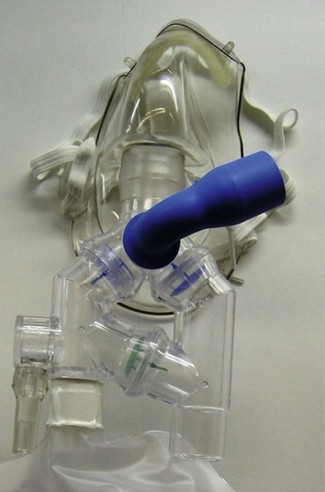
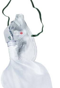
One example of a high-capacity mask (Fig. 7.8) uses a sequential gas delivery system incorporated in a small circuit below the mask with a one-way valve to prevent re-breathing, an expiratory valve and a third valve to allow entrainment of room air should the reservoir bag become exhausted. This design is reputed to allow FIO2 close to 1.0 to be given, although again attention to the seal between the mask and the face and the oxygen flow rate is required to achieve this.8 A more recent high capacity mask (Intersurgical, UK) again incorporates a one-way valve from the reservoir bag but designed such that it also allows entrainment of room air if the bag is emptied (Fig. 7.9). This and the expiratory one way valve are neatly arranged within the front of the mask itself. Additionally this device is made of non-PVC materials, in an attempt to reduce the impact on the environment during disposal.
Generally, it is accepted that facemasks with reservoir bags probably deliver an FIO2 between 0.6 and 0.8;9,10 however, in reality there is likely to be considerable variation around these values due to leak between the mask and face combined with variable respiratory patterns. Best results will be achieved by using an O2 flow rate adequate for the patient’s needs such that the reservoir bag empties by no more than a third during inspiration and by achieving the best seal possible between the mask and the face. Some masks incorporate additional features, for example a small chimney containing a red polystyrene ball that moves up and down with respiration so that a patient’s respiratory effort can be visualized and respiratory rate can easily be measured (Fig. 7.10).11
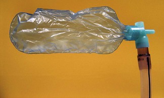
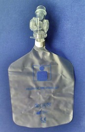
A reservoir bag may also be attached to airway maintenance devices to improve the FIO2 delivered during emergence from anaesthesia. The T-Bag (Ultimate Medical Pty Ltd, Australia) (Fig. 7.11) consists of a reservoir bag with a capacity of 300 ml, attached via a 15 mm internal diameter ISO connector to a laryngeal mask (LM) or endotracheal tube (TT). There is a 3 mm connector that feeds oxygen directly into the reservoir bag and also a 10 mm port, which is open to the atmosphere. During inspiration, the reservoir bag, with its 15 mm aperture, provides a greater proportion of inspiratory gas. A smaller amount is entrained through the 10 mm port, which has a higher resistance to flow. During exhalation, this process is reversed until the reservoir bag is full. Subsequent exhalate then leaves via the 10 mm port only. The T-Bag is light enough not to displace the LM, provides visual confirmation of spontaneous ventilation and supplies a FIO2 of up to 0.70 with an oxygen supply rate of 6 l min−1. It is also possible to ventilate patients briefly by occluding the 10 mm port with a digit, with additional volume being delivered by squeezing the bag.
Very high capacity oxygen delivery devices (capacity >2500 ml)
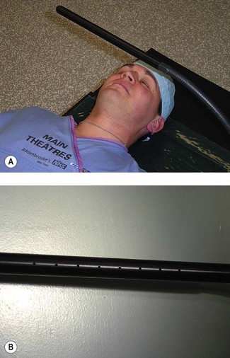
During ophthalmic surgery under local anaesthesia, oxygen is sometimes administered under the drapes using an eye surgery bar (Fig. 7.12A). The bar is hollow (Fig. 7.12B). Oxygen is fed into the bar at one end and escapes through perforations in the bar where it is in close proximity to the patient. There are many different designs and some are ‘home made’. Oxygen flow under the drapes (which acts as a large reservoir) increases the FIO2, helps reduce rebreathing of CO2, and provides a refreshing breeze on the patient’s face, when otherwise they may begin to feel hot and claustrophobic.12
Fixed performance devices
• when following guidelines for the management of patients with exacerbation of COPD, which state that a fixed FIO2 be employed13
• when administering supplemental oxygen to a critically ill patient for whom an accurate calculation of the PaO2 / FIO2 ratio is needed to guide decisions about intubation or diagnose acute respiratory distress syndrome.14
The Bernoulli effect and the Venturi principle
The Bernoulli effect (Fig. 7.13A) describes the change in pressure that occurs when a fluid flows through a constriction. The fluid accelerates, gaining kinetic energy at the expense of potential energy; as a result, the pressure distal to the constriction is reduced. The Venturi principle uses this phenomenon to allow a second fluid to be entrained into the stream of the first, either through a side arm that opens into the area of low pressure or via a co-axial arrangement (Fig. 7.13B).
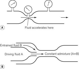
Referring to Fig. 7.13B, the degree of pressure drop and resultant entrainment is dependent on the flow rate of fluid A, the physical dimensions of the constriction and the density and viscosity of fluids A and B. Hence Venturis for oxygen delivery devices can be designed to entrain a known amount of air into a stream of oxygen at a specified flow rate, providing a fixed final FIO2 (Table 7.3).
Table 7.3 Fraction of inspired oxygen, oxygen flow rates and air entrainment of widely used Venturi devices
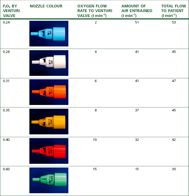
The performance of Venturi devices is less dependent on respiratory pattern as they use relatively high oxygen flow rates to which is added the flow rate of entrained air. The total flow rate is close to or exceeds the patient’s peak inspiratory flow rate, and is sufficient to flush away alveolar gas expired into the mask. The Venturi devices that entrain most air deliver a lower FIO2 and are thus most reliable, but those that deliver high FIO2, especially the 60% O2 device, entrain less air and also have a lower total flow rate into the mask, which may be inadequate in a patient breathing with a high peak inspiratory flow rate and can also result in rebreathing. Hence the highest FIO2 Venturi devices may underperform by 5–10%.15
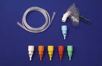
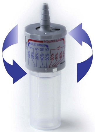
Numerous manufacturers produce single-use clear plastic oxygen masks which come prepacked with a number of different Venturi injectors (Fig. 7.14), typically giving overall flow rates of 30–60 l min−1, as detailed in Table 7.3. Adjustable Venturi devices are also available (Fig. 7.15), where the user can select the FIO2 required by adjusting the size of the air entrainment aperture, before the total fresh gas flow is passed through a humidifier.
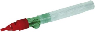
A Venturi can also be attached to a T-piece (Fig. 7.16) so that supplemental oxygen can be delivered to patients who are breathing spontaneously through a supraglottic airway or less commonly a tracheal tube.16 These devices are used on a short-term basis in recovery areas during emergence from anaesthesia. The segment of 22 mm diameter corrugated tubing has a volume of 56 ml, a compromise between oxygen enrichment and rebreathing. It provides a reservoir of oxygen-enriched air, which the patient inhales during the short period of the respiratory cycle in which peak inspiratory flow rate exceeds oxygen flow into the device. Pressure within the tubing is above atmospheric pressure as a result of the oxygen flow, creating a pressure gradient between the tubing and the room. Therefore, the presence of the tubing also provides 1–2 cm H2O of continuous positive airway pressure (CPAP).
Medium dependency systems
• to improve oxygenation during respiratory emergencies that result in impaired gas exchange
The continuous pressure increases functional residual capacity of the lungs and reduces airway collapse.18 CPAP may be applied by means of a tightly fitting mask, mouthpiece or helmet or else directly to an endotracheal or tracheostomy tube. Bi-level positive airway pressure (BiPAP) can also be applied in the same way, but requires an appropriate ventilator (see Chapter 10) and is mainly used in exacerbations of chronic obstructive pulmonary disease and acute cardiogenic pulmonary oedema.19
Many CPAP or BiPAP facemasks cover the mouth and nose. A variety of sizes are available as a good seal is essential; the mask is secured with a harness (Fig. 7.17). Because of the difficulty of achieving and maintaining a good seal, CPAP helmets have been developed to cover the entire head (Fig. 7.18).
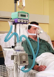
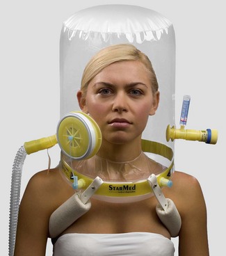
Figure 7.18 CaStar non-invasive ventilation/CPAP hood. StarMed SpA, Italy.
(Photograph courtesy of StarMed SpA).
Some designs of CPAP facemask have a 22 mm female taper inlet similar to anaesthetic facemasks. In this case, a ‘T’- or ‘Y’-shaped connector on the mask allows oxygen delivery to one limb with the CPAP valve situated on the other. Other designs have two taper inlets, one for oxygen delivery and the second to accommodate the CPAP valve directly. For greater comfort and better tolerance, CPAP may be applied only to the nose, for example in neonatal respiratory distress syndrome (by means of nasal cannulae) and in the treatment of obstructive sleep apnoea. Under such circumstances pharyngeal valve mechanisms, including the soft palate, prevent loss of airway pressure through the mouth. Commercial CPAP valves can provide 2.5–20 cm H2O of CPAP (Fig. 7.19).
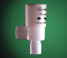
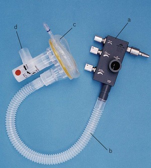
The fresh gas flow in the CPAP circuit must exceed maximal inspiratory gas flow in order to maintain the same positive pressure throughout the respiratory cycle. Some systems incorporate a spring loaded reservoir bag; otherwise a flow generator connected to the piped high pressure oxygen outlet (‘wall’ CPAP) is used (Fig. 7.20). The flow generator is a high-pressure oxygen-driven Venturi injector and most devices of this nature tend to be quite noisy. To ensure that CPAP is maintained during all phases of respiration, it is important to check that the CPAP valve is being kept open by an adequate flow throughout the respiratory cycle. Humidification and oxygen monitoring units can be added to the system (Fig. 7.17). Humidification is difficult, however, when using a CPAP helmet due to problematic steaming and condensation.
Intubated patients being weaned from a ventilator may receive oxygen and CPAP through a T-piece arrangement with a CPAP valve connected to the distal end. This has the advantage of doing away with the work of breathing necessary for triggering gas flow from a ventilator.
High-dependency systems
In addition to supplying supplemental oxygen, brief periods of low-level positive pressure ventilation may be applied by means of a nasal mask or facemask, avoiding the need for tracheal intubation. Non-invasive positive pressure ventilation (NIPPV or ‘NIPPY’) can be used electively to treat patients with central apnoea syndromes, neuromuscular or chest wall disease. It is increasingly used in acute respiratory failure and weaning.20 The equipment used is the same as that required for CPAP, with the addition of a sophisticated intensive care ventilator capable of providing synchronized intermittent mandatory bi-level ventilation. For home use, highly sophisticated CPAP and BiPAP equipment is available, including some that use microprocessor control to adjust their own settings and can be controlled by telemetry.21
Metered sources of oxygen and air
The high flow rates required for CPAP need a metered source of fresh gas. The flow generator in the CPAP equipment (Fig. 7.20) plugs into a terminal outlet for oxygen via a Schrader probe (a quick release, gas specific connector, Chapter 1), typically the hospital piped oxygen supply or, sometimes, an oxygen cylinder. It has an ‘on’ switch and adjustments for FIO2 and flow rate. Air is entrained into the device through an adjustable Venturi orifice to determine FIO2 and flow rate is adjusted by means of a variable pressure regulator. Flow generators such as these can also be used in conjunction with a humidifier to provide high flow oxygen therapy delivered through a conventional loose fitting mask (aerosol mask) or high flow nasal cannulae systems (Fig. 7.4).
The administration of oxygen in a mixture of gasses
Entonox
The physical properties, storage and supply of this 50 : 50 mixture of oxygen and nitrous oxide (N2O) are described in Chapter 1. This chapter will describe the equipment used for the self-administration of Entonox during labour and for short painful procedures such as fracture reduction, drain removal or dressing changes.
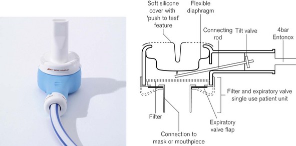
The BOC Entonox valve
The original valve (Fig. 7.21) is no longer manufactured, but is described here as many are still in use. It clamps directly to a pin-index Entonox cylinder and is composed of a first-stage pressure regulator and second-stage demand valve. The demand valve consists of a sensitive rubber diaphragm that is deformed by negative pressure generated when a patient begins to inhale. The diaphragm operates a push rod that in turn tilts a flap to open the valve. A corrugated hose carries the Entonox to a facemask or mouthpiece, which contains an exhalation valve. The sensing diaphragm can be manually depressed to test the integrity of the system.
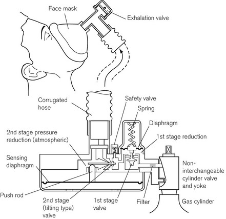
The successor to this valve is shown in figure 7.22. Note that like the Pneupac valve below it relies on a separate and remote first stage pressure reduction valve to deliver gasses at 4 bar to the valve.
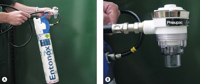
The Pneupac Entonox valve
This valve is shown in figure 7.23 connected to a lightweight Entonox cylinder with an integral pressure reducing valve. The advantage of this system compared to the original BOC valve in figure 7.21 is that the high pressure hose may be several metres long so that the Entonox cylinder can be stored remotely from the facemask. This allows the cylinder to be kept warm inside the ambulance when administering Entonox at the roadside in cold conditions. This model also incorporates a ‘push to test’ feature that can be used for manual insufflation if desired.
Heliox
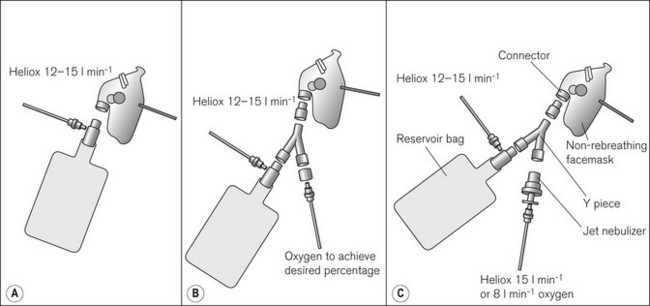
Heliox is presented in the UK as Heliox21 – a mixture of 21% oxygen and 79% helium. Helium is less dense than oxygen and nitrogen, and hence is more likely to flow in a laminar fashion in narrow airways, reducing the amount of less efficient turbulent flow (and the majority of transitional flow states). Additionally, this allows faster diffusion of oxygen and carbon dioxide in the distal parts of the lung. Published literature describes the use of Heliox in acute asthma, chronic obstructive pulmonary disease (COPD) exacerbation, croup, bronchiolitis, post extubation stridor, as well as upper airway obstruction.22 Whilst there is little doubt of its usefulness in upper airway obstruction, the evidence for its use in lower airway obstruction is less convincing, leading Cochrane reviewers to conclude that Heliox therapy has little to offer in the initial treatment of acute exacerbations and routine treatment of all acute asthma episodes.23 Whilst a more pronounced effect has been noted in more severe acute asthma, it is still unclear whether Heliox can avert tracheal intubation, or reduce intensive care and hospital admission rates, duration of stay or mortality.1,23 However, failure to exclude room air dilution of the Heliox mixtures used in many asthma studies may partly explain some disappointing results.1,7 Supplemental oxygen can easily be added to Heliox using a Y-piece in the delivery circuit (Fig. 7.24), although it should be remembered that like diluting Heliox with room air, admixture of greater quantities of oxygen will increase the density of the gas mixture and increase the work of breathing. Additionally, nebulized drugs can be added to Heliox and, using helium as the carrier gas for nebulized drug delivery (Fig. 7.24C), may allow for better drug delivery to the lung periphery due to increased flows through the upper generations of the bronchial tree. However, Heliox reduces the efficiency of the nebulizer and so increased flows are required (compared to oxygen or air nebulizer flows).24 Because of the need to rigidly exclude room air from the inhaled Heliox mixture, it is best to use a gas-tight delivery system with an adequate reservoir combined with a leak-free interface to the patient’s face.7,24 This type of breathing system must incorporate an entrainment valve, so that the patient can breathe room air in the event of fresh gas flow failure. Humidification of Heliox may also be important for longer-term use. A recently introduced breathing system (BOC Medical) aims to meet the needs of a specific Heliox administration system. The device consists of a 2L reservoir bag attached to the inlet of an angle piece that houses a unidirectional inspiratory valve, the entrainment valve, an expiratory valve and an inlet for the Heliox. The outlet has a 22 mm male ISO connector that can be attached to an anaesthetic or CPAP/BiPAP facemask (Fig. 7.25).
Heliox is sometimes administered to ventilated patients, especially children, via the air inlet of a ventilator. The altered density of the fresh gas within the ventilator has a significant and unpredictable effect on delivered FIO2 and tidal volume.25 Extra care should be taken in these circumstances to avoid barotrauma and detect over- or under-ventilation.
Oxygen delivery at high or low atmospheric pressures
Hyperbaric medicine
Hyperbaric oxygen is most commonly used to treat decompression sickness and carbon monoxide poisoning.26 Breathing oxygen at three times normal atmospheric pressure (absolute pressure) increases the amount of dissolved oxygen in plasma from a maximum of 2 ml 100 ml−1 to 6 ml 100 ml−1, resulting in an extra 200 ml min−1 of oxygen delivery. As a result of this perceived physiological benefit, the US Food and Drug Administration (FDA) has approved 11 other application areas for hyperbaric oxygen, including the treatment of gas gangrene, necrotizing fasciitis, osteoradionecrosis, skin flaps and grafts, chronic refractory osteomyelitis, thermal burns and compartment syndrome.27 However, the evidence for its efficacy in these latter conditions is unclear; most have not been investigated in clinical trials and many are based upon case reports or small series.
There are three types of hyperbaric chamber. Those in medical use tend to be divided into type A and type B on the basis of their size. The type A chamber (Fig. 7.26A and B) is large enough to accommodate one or more critically ill ventilated patients plus medical staff and equipment. The chamber shown was situated in the Hyperbaric Medicine Unit in the Royal Hospital, Haslar, UK. It could be adapted to accommodate ten or more sitting patients. Large chambers may have air conditioning and humidity control systems as the temperature of air rises as it is compressed. Hyperbaric chambers have multiple antistatic points to prevent build-up of electrical charge, an essential safety feature, as a spark in an enriched oxygen environment at 3 atm would result in a violent explosion. Compressing the chamber with air whilst the occupants breathe oxygen via a tightly fitting facemask (Fig. 7.26C) or head tent further reduces risk of explosion.
Figure 7.26 A. and B. The Type A hyperbaric chamber at the former Royal Hospital, Haslar
(courtesy of Royal Navy and Qinetiq Ltd).
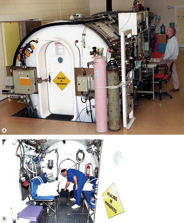
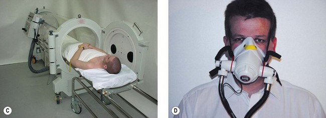
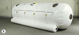
Type B chambers are smaller and less suitable for ventilated patients. In the UK, hyperbaric chambers are often situated in deep sea diving centres, although small, single-patient portable chambers are also available (Fig. 7.26D). Lightweight and portable equipment has been developed to treat acute life-threatening mountain sickness and decompression sickness on the scene, to transport patients suffering from decompression sickness and to pressurize patients during flight in non-pressurized aeroplanes.28 These are sometimes referred to as ‘mild chambers’ in reference to the much lower pressures achieved (1.3 atm absolute) with these soft-sided inflatable chambers (Fig. 7.26E).
Diving
Divers face several problems when breathing underwater at increased atmospheric pressure.29 Pressure increases by one atmosphere for every 10 m of descent:
• Nitrogen: this poorly soluble gas is thought to be physiologically inert, but at high pressure it is forced into solution in the tissues. If ascent is too rapid, bubbles of N2 form causing decompression sickness (’the bends’), which is potentially fatal. At depths of 50 m or more, N2 causes narcosis by an unknown mechanism (rapture of the deep).
• Oxygen: high concentrations of oxygen cause lung injury and are toxic to the central nervous system. Convulsions can occur after breathing O2 at 4 atm for 30 min.
To combat these problems divers use a variety of gas mixtures: to increase the amount of time that they may stay at depth without the need for decompression stops when ascending, to reduce the risk of decompression sickness by decreasing the amount of dissolved nitrogen in the body and to avoid oxygen toxicity. Nitrogen may be partially or completely replaced by helium, which is not narcotic and reduces the work of breathing at very high pressures. For very deep dives, the oxygen content of the diving gas may be as low as 1%.30
Most divers use an open-circuit self-contained underwater breathing apparatus (Scuba).30 The chosen gas is contained in steel, aluminium or titanium cylinders. Tank volume is normally about 10 L, but may be very small (‘bail out bottles’) or up to 15 L for deeper or longer exposures. A balanced first-stage regulator situated on the tank reduces gas pressure to 10 atm. Gas then passes through an intermediate hose to a second regulator on the mouthpiece where it is balanced to the pressure of the surroundings and the lungs. When the diver exerts a slight negative pressure on the regulator at the start of inspiration, a non-return valve between the hose and mouthpiece opens and initiates fresh gas flow. Expiration and positive pressure closes the valve and expired gas is lost to the open water. Scuba equipment allows easy breathing with little resistance to inhalation and expiration independent of tank pressure. Safety is of paramount importance: tanks are visually inspected annually and subjected to a hydrostatic test procedure every 5 years and the resistance offered by each regulator, accuracy of instruments and integrity of hoses are checked regularly. An additional safety feature is a pinhole orifice in the proximal end of the high-pressure hose, which prevents injury from a flailing hose should it rupture.
Military, cave and specialist divers may choose to use a closed circuit system in shallow dives when it is important not to produce bubbles.30 The diver typically breathes 100% oxygen via a reservoir bag, which is then exhaled via a non-return valve into a canister containing a CO2 absorber. The expired oxygen is recycled back into the reservoir bag, which is supplemented by additional oxygen from the high-pressure supply. Use of mixed gasses may allow deeper dives using a closed circuit system, with electronic monitoring of gas levels to ensure that their levels are maintained within safe ranges. A high degree of training and expertise is required to dive safely with such equipment. This system offers a higher resistance to breathing and CO2 is liable to accumulate due to absorber inefficiency in moist, cold environments.
Mountaineering
Mountaineers require oxygen to facilitate climbing at very high altitude or to manage medical emergencies.31 Closed circuit systems that use soda lime to absorb expired carbon dioxide have been used, but are unreliable, as internal valves tend to ice up before the soda lime begins to warm up and work. Constant-flow systems have become most popular, mainly because of their simplicity. Weighing 3–7 kg in total, they comprise light titanium cylinders containing special no water oxygen at 306 atm, pressure reducing valves and regulators. The regulator permits flow of 0.5–4 l min−1 into a rubber or plastic reservoir and facemask via light, non-kinking tubing. Finally, the mask is secured to the face in a helmet or with straps. All systems are checked and tested for several hours in a ‘cold room’ at −20°C before an expedition, paying particular attention to humidification, and the pooling of condensate or deposition of ice particles.32
1 Ho AM, Lee A, Karmakar MK, Dion PW, Chung DC, Contardi LH. Heliox vs air-oxygen mixtures for the treatment of patients with acute asthma: a systematic overview. Chest. 2003;123:882–890.
2 Collis JM, Bethune DW. Oxygen by face mask and nasal catheter. Lancet. 1967;1:787–788.
3 Ooi R, Joshi P, Soni N. An evaluation of oxygen delivery using nasal prongs. Anaesthesia. 1992;47:591–593.
4 Sim MA, Dean P, Kinsella J, Black R, Carter R, Hughes M. Performance of oxygen delivery devices when the breathing pattern of respiratory failure is simulated. Anaesthesia. 2008;63:938–940.
5 Groves N, Tobin A. High flow nasal oxygen generates positive airway pressure in adult volunteers. Aust Crit Care. 2007;20:126–131.
6 Campkin NT, Ooi RG, Soni NC. The rebreathing characteristics of the Hudson oxygen mask. Anaesthesia. 1993;48:239–242.
7 Standley TD, Smith HL, Brennan LJ, Wilkins IA, Bradley PG, Barrera Groba C, et al. Room air dilution of Heliox given by facemask. Intensive Care Med. 2008;34:1469–1476.
8 Slessarev M, Somogyi R, Preiss D, Vesely A, Sasano H, Fisher JA. Efficiency of oxygen administration: sequential gas delivery versus ‘flow into a cone’ methods. Crit Care Med. 2006;34:829–834.
9 Cairo JM. Administering medical gasses: regulators, flowmeters, and controlling devices. In: Cairo JM, Pilbeam SP, eds. Mosby’s respiratory care equipment. St. Louis: Mosby; 1999:62–88.
10 Branson RD. The nuts and bolts of increasing arterial oxygenation: devices and techniques. Respir Care. 1993;38:672–686. discussion 87–9
11 Breakell A, Townsend-Rose C. The clinical evaluation of the Respi-check mask: a new oxygen mask incorporating a breathing indicator. Emerg Med J. 2001;18:366–369.
12 Rayen AT. A device for oxygen administration during ophthalmic surgery under local anaesthesia. Anaesthesia. 2000;55:508–509.
13 O’Driscoll BR, Howard LS, Davison AG. BTS guideline for emergency oxygen use in adult patients. Thorax. 2008;63(Suppl 6):vi1–v68.
14 Bernard GR, Artigas A, Brigham KL, Carlet J, Falke K, Hudson L, et al. The American-European Consensus Conference on ARDS. Definitions, mechanisms, relevant outcomes, and clinical trial coordination. Am J Respir Crit Care Med. 1994;149:818–824.
15 Jones HA, Turner SL, Hughes JM. Performance of the large-reservoir oxygen mask (Ventimask). Lancet. 1984;1:1427–1431.
16 Campbell DJ, Fairfield MC. The delivery of oxygen by a Venturi T piece. Anaesthesia. 1996;51:558–560.
17 Duncan AW, Oh TE, Hillman DR. PEEP and CPAP. Anaesth Intensive Care. 1986;14:236–250.
18 Lindner KH, Lotz P, Ahnefeld FW. Continuous positive airway pressure effect on functional residual capacity, vital capacity and its subdivisions. Chest. 1987;92:66–70.
19 Nava S, Hill N. Non-invasive ventilation in acute respiratory failure. Lancet. 2009;374:250–259.
20 Brochard L, Mancebo J, Elliott MW. Noninvasive ventilation for acute respiratory failure. Eur Respir J. 2002;19:712–721.
21 Highcock MP, Morrish E, Jamieson S, Shneerson JM, Smith IE. An overnight comparison of two ventilators used in the treatment of chronic respiratory failure. Eur Respir J. 2002;20:942–945.
22 Ball JAS, Rhodes A, Grounds RM. A review of the use of helium in the treatment of acute respiratory failure. Clin Intensive Care. 2001;12:105–113.
23 Rodrigo G, Pollack C, Rodrigo C, Rowe BH. Heliox for nonintubated acute asthma patients. Cochrane Database Systematic Review 2006;4:CD002884.
24 Corcoran TE, Gamard S. Development of aerosol drug delivery with helium oxygen gas mixtures. J Aerosol Med. 2004;17:299–309.
25 Berkenbosch JW, Grueber RE, Dabbagh O, McKibben AW. Effect of helium-oxygen (Heliox) gas mixtures on the function of four pediatric ventilators. Crit Care Med. 2003;31:2052–2058.
26 Tibbles PM, Perrotta PL. Treatment of carbon monoxide poisoning: a critical review of human outcome studies comparing normobaric oxygen with hyperbaric oxygen. Ann Emerg Med. 1994;24:269–276.
27 Guo S, Counte MA, Romeis JC. Hyperbaric oxygen technology: an overview of its applications, efficacy, and cost-effectiveness. Int J Technol Assess Health Care. 2003;19:339–346.
28 Dubois C, Herry JP, Kayser B. Portable hyperbaric medicine, some history. J Wilderness Med. 1994;5:190–198.
29 Spira A. Diving and marine medicine review part I: diving physics and physiology. J Travel Med. 1999;6:32–44.
30 Egstrom GH. Diving equipment. In: Bove AA, ed. Bove and Davis’ Diving medicine. 3rd ed. London: Saunders; 1997:26–38.
31 West JB. Man at extreme altitude. J Appl Physiol. 1982;52:1393–1399.
32 Hendricks DM, Pollock NW, Natoli MJ, Vann RD. Mountaineering oxygen mask performance at 4572 m. Aviat Space Environ Med. 2000;71:1142–1147.
[/level-membership-for-anesthesiology-category][not-level-membership-for-anesthesiology-category]
Chapter 7 Equipment for the inhalation of oxygen and other gasses
Introduction
The benefits of supplemental oxygen are:
• as a treatment for hypoxaemia due to hypoventilation, or due to gas transfer or ventilation/perfusion abnormalities (e.g. heart failure, anaesthesia)
• to improve oxygen supply to tissues, when a disease process causes oxygen demand to outstrip delivery (e.g. severe sepsis, malignant hyperpyrexia)
• as a specific treatment for certain conditions, e.g. carbon monoxide poisoning, postoperative nausea and vomiting
• to allow humans to survive at very low atmospheric pressure, e.g. mountaineering and high altitude flying.
Normobaric oxygen therapy
There are almost as many devices that deliver oxygen as there are indications for its use. These devices may be classified by the extent to which the patient relies upon them to correct any deficiency in oxygen delivery (Table 7.1).
Table 7.1 A classification of oxygen delivery devices by degrees of dependency
CPAP, continuous positive airway pressure; NIPPV, non-invasive positive pressure ventilation; IPPV, intermittent positive pressure ventilation
Low dependency systems
Variable performance devices
With these devices, the oxygen concentration delivered to the upper airway varies with the phase and pattern of respiration (as well as the selected oxygen flow rate). As an example, consider a standard oxygen mask applied to the face (Fig. 7.1). Oxygen flows into the facemask from a continuous supply and quickly fills the relatively small volume of the mask (approximately 200 ml) at the end of an exhaled breath. The oxygen then begins to escape through the mask’s vents and where the seal against the face is imperfect.
The complex interplay between the factors that determine FIO2 (Table 7.2) means that most oxygen delivery devices deliver a variable FIO2. The extent of this variability is difficult to quantify as normal methods of measuring breathing pattern are impractical in clinical practice. The latter require a mouthpiece that interferes with oxygen flow in the mask, and subjects are not able to breathe with a fixed respiratory pattern long enough for accurate measurements to be recorded. These difficulties explain why the factors most influential in determining FIO2 are still unclear.
No capacity oxygen delivery devices
Traditionally, nasal cannulae (also known as nasal prongs or specs) deliver unhumidified oxygen to the nasopharynx (Fig. 7.2). They are more comfortable and less claustrophobic than facemasks, allowing talking, eating and drinking, and making them the most suitable means of delivering long-term oxygen therapy for chronic conditions, especially at home. The main drawback is that an unhumidified oxygen flow greater than 2 L min−1 can cause discomfort and drying of the nasal mucosa. Thus unhumidified oxygen therapy in association with the tiny capacity of the nasal cannulae leads to variable FIO2. Clinical and laboratory studies in this context have shown an enormous variability with respiratory pattern, FIO2 ranging between 0.26 and 0.90.2,3 A further design is the nasal sponge (tipped) catheter, which is lodged in one nostril and again effectively uses the nasopharynx as a small reservoir during the respiratory pause (Fig. 7.3). Devices permitting humidified oxygen therapy via nasal cannulae are now available (Fig. 7.4), allowing oxygen flow rates up to 60 L min−1 to be tolerated for long periods. As a result, consistently higher, more reliable FIO2 can be achieved with this form of high flow humidified oxygen therapy.4 However, warm humidified gas is a good medium for bacterial growth; therefore, it is mandatory that any disinfection and infection control procedures deemed necessary by manufacturers and regulatory authorities are adhered to. The other point to note is that delivering high flows into the nasopharynx generates a small amount of positive end expiratory pressure (PEEP) depending on the flow used and if the mouth is open or closed. Pharyngeal pressures of up to 4 cm H2O have been recorded with a flow of 60 L min−1 with the mouth open, increasing to nearly 10 cm H2O with the mouth closed.5 As such, high flow humidified oxygen therapy delivered via nasal cannulae should be regarded as a medium dependency device (see below). Its role in the management of acutely breathless patients is becoming increasingly appreciated.
Low capacity oxygen delivery devices (capacity <100 ml)
Facemasks for children, or tracheostomy masks (Fig. 7.5) have a volume of approximately 70–100 ml. Tracheostomy masks, especially, do not provide humidification without extra equipment, and so are best suited for short-term use. In long-term use, oxygen may be humidified by using a ‘Swedish nose’ device (Fig. 7.6) (see also Chapter 11, Humidifiers). This is a small, light heat and moisture exchanger that connects to the tracheostomy tube by means of a 15 mm International Organization for Standards (ISO) connector. Supplemental oxygen can be administered into this via a clip-on device. A ‘Swedish nose’ may also provide 2.5–5 cm H2O of PEEP.
Medium capacity oxygen delivery devices (capacity 100–250 ml)
Standard adult facemasks are designed to cover the nose and mouth and have a capacity of approximately 175–200 ml (Fig. 7.1); there are a multitude of different designs. They are, almost without exception, made of transparent soft plastic with an elastic strap to secure the mask in place. Some incorporate a short deformable metal bar allowing the mask to be shaped around the nose to achieve a closer fit. Oxygen flow rates of 2–15 l min−1 result in a highly variable and unpredictable FIO2. Rebreathing of CO2 can occur with O2 flow rates of less than 2 L O2 min−1 or if minute ventilation is very high.6 A more recent design (Intersurgical, UK) fits filters in the expiratory ports, in an attempt to reduce infection risk from aerosolized pathogens emitted from the patient’s airway.
High capacity oxygen delivery devices (capacity 250–2500 ml)
Air is only entrained into a facemask when the patient’s inspiratory flow rate exceeds the oxygen supply rate. To achieve a FIO2 near 1.0 (100% oxygen) by providing sufficient oxygen flow alone, rates in excess of 60 l min−1 would be required (in order to exceed the patient’s peak inspiratory flow rate) which is clearly impractical. Increasing mask size simply increases the risk of rebreathing CO2. However, a great deal of oxygen delivered to the facemask is lost to the atmosphere whenever the patient’s inspiratory flow rate is (a) less than the oxygen supply rate and (b) during exhalation. High-capacity masks are designed to store some of this wasted oxygen in a reservoir bag (usually of >1 litre volume) attached to the facemask, thus providing a higher FIO2 (Fig. 7.7). With these devices, oxygen flows directly into the reservoir bag, which fills during exhalation and whenever the patient’s inspiratory flow rate is less than the flow rate of delivered oxygen. The patient inhales oxygen preferentially from the reservoir bag: provided the mask makes a reasonable seal to the face. Expiratory flap valves are incorporated on the vents or in piping below the mask to prevent air entrainment from these sites. However, ambient air will still be entrained if there are leaks between the mask and the face.7 Some manufacturers include a one-way valve between mask and reservoir bag, reducing rebreathing of CO2. However, higher oxygen supply rates are required as oxygen in the exhaled dead space of the mask, pharynx and upper trachea is prevented from entering the reservoir bag and is wasted. A valveless device is, therefore, most suitable when oxygen supplies are limited, but a valve is desirable if rebreathing of CO2 would be detrimental, for example after head injury.
One example of a high-capacity mask (Fig. 7.8) uses a sequential gas delivery system incorporated in a small circuit below the mask with a one-way valve to prevent re-breathing, an expiratory valve and a third valve to allow entrainment of room air should the reservoir bag become exhausted. This design is reputed to allow FIO2 close to 1.0 to be given, although again attention to the seal between the mask and the face and the oxygen flow rate is required to achieve this.8 A more recent high capacity mask (Intersurgical, UK) again incorporates a one-way valve from the reservoir bag but designed such that it also allows entrainment of room air if the bag is emptied (Fig. 7.9). This and the expiratory one way valve are neatly arranged within the front of the mask itself. Additionally this device is made of non-PVC materials, in an attempt to reduce the impact on the environment during disposal.
Generally, it is accepted that facemasks with reservoir bags probably deliver an FIO2 between 0.6 and 0.8;9,10 however, in reality there is likely to be considerable variation around these values due to leak between the mask and face combined with variable respiratory patterns. Best results will be achieved by using an O2 flow rate adequate for the patient’s needs such that the reservoir bag empties by no more than a third during inspiration and by achieving the best seal possible between the mask and the face. Some masks incorporate additional features, for example a small chimney containing a red polystyrene ball that moves up and down with respiration so that a patient’s respiratory effort can be visualized and respiratory rate can easily be measured (Fig. 7.10).11
A reservoir bag may also be attached to airway maintenance devices to improve the FIO2 delivered during emergence from anaesthesia. The T-Bag (Ultimate Medical Pty Ltd, Australia) (Fig. 7.11
[/not-level-membership-for-anesthesiology-category]
