Chapter 26 Electrophysiological Evaluation of Recurrent Ventricular Tachycardia
Introduction
Ventricular tachycardia (VT) is typically an ominous sign in the setting of structural heart disease. Its evolution to ventricular fibrillation (VF) and sudden cardiac death (SCD) has become increasingly recognized. Patients at particularly high risk are those with chronic coronary artery disease (CAD) with prior myocardial infarction (MI) and marked left ventricular (LV) systolic dysfunction.1 In the post-thrombolytic era, the incidence of sustained VT after MI is still approximately 2% to 4% in the first 48 hours and then stabilizes to about 0.5% per year thereafter. As many as 5% to 10% of the patients will experience VF or SCD that is usually preceded by sustained VT.2,3 An estimated 40% of individuals who have an implantable cardioverter defibrillator (ICD) placed for an index event of sustained VT will have recurrent VT.4,5 However, all VTs are not equal by nature; some can occur in the absence of structural heart disease and have a very benign prognosis. The disease states associated with VT and the management of VT will be addressed in greater length in other chapters of this text. This chapter will delineate the approach to the electrophysiological evaluation of recurrent VT.
Mechanisms
Abnormal Automaticity
Normal automaticity refers to reliable depolarization and impulse formation of pacemaker cells. Such cells in the ventricle normally provide escape rhythms of less than 50 beats/min. VT caused by abnormal automaticity may occur when ventricular myocytes generate impulse formation at an accelerated rate compared with the normal rate because of an altered threshold for sodium (Na+) influx into the cells. This mechanism is thought to underlie accelerated idioventricular rhythms in the setting of acute hypokalemia, hypomagnesemia, cocaine intoxication, focal inflammation, acute myocarditis, or ischemia.5 In the absence of such derangements, VTs of this type typically are seen in children or young adults.
Triggered Activity
Action potentials may occasionally propagate afterdepolarizations caused by oscillations in the membrane potential. Such triggered activity may either occur as early afterdepolarizations (EADs) or delayed afterdepolarizations (DADs). EADs occur during phase II or III of the action potential, are more likely to occur during bradycardia, and are implicated in torsades de pointes induced by drugs or electrolyte abnormalities and in some variants of congenital long QT syndrome (LQTS). DADs occur during phase IV of the action potential, are more tachycardia dependent, and are believed to be responsible for ventricular arrhythmias occurring in digitalis intoxication and outflow tract VTs.5 The mechanism may also play a role in VT in the setting of acute MI.5
Re-entry
Re-entry is, by far, the most common mechanism of VT associated with structural heart disease. Clinical characteristics include spontaneous induction by premature ventricular complexes with usually abrupt initiation and termination. It requires tissue that can conduct unidirectionally with either fixed or functional block as well as a region of relatively slow conduction that permits recovery of previously depolarized tissue and a circus rhythm to propagate. The mechanism underlying most VTs in the setting of structural heart disease is re-entry caused by a scar. Although a myocardial scar or functional block caused by a nonischemic insult can serve as the pathophysiological substrate, chronic CAD with prior infarct, particularly in the setting of compromised LV function, is the most common underlying pathology.1
Noninvasive Assessment
Surface Electrocardiogram
As in the face of any wide-complex tachycardia, a supraventricular etiology, with intrinsic bundle branch block, aberrancy, or antegrade accessory pathway conduction, should first be ruled out. The baseline electrocardiogram (ECG) can be very helpful in the initial assessment of presumed VT.5 The presence of a bundle branch block or manifest pre-excitation at baseline that is identical to that seen during clinical tachycardia speaks against VT as a diagnosis. Importantly, even minor differences in the wide QRS complex tachycardia compared with the sinus rhythm recording suggest a ventricular origin. The presence of Q waves in contiguous leads or ST elevations in the absence of acute MI suggests prior MI and aneurysm with a scar, respectively, and strongly suggests VT, especially if the infarct site is consistent with the presumed VT exit (see below). The presence of a widened QRS at baseline, which is a marker of His-Purkinje disease, suggests a predisposition for bundle branch re-entrant or fascicular VT. If a 12-lead ECG of the clinical arrhythmia is available, the presence of ventriculoatrial dissociation or capture or fusion beats is diagnostic for VT. Additional axis and morphology characteristics may also be present that may point toward VT as the diagnosis.3,6
If a 12-lead ECG has been obtained during VT, much additional information may be gleaned from it. First, the “clinical” VT will be apparent, which will be of great assistance during electrophysiological study prior to ablation. Pacemapping strategies will be greatly assisted by this in the setting of poorly hemodynamically tolerated or noninducible VTs and substrate-based ablation (discussed in later chapters). Knowing which of many potentially inducible VTs during electrophysiological study are pertinent also will ensure that those VTs are targeted during the ablation procedure. Finally, a likely “site of origin,” or at least close approximation of the VT exit from a larger macro–re-entrant circuit, can often be determined.7
A general strategy should begin with determining the bundle branch morphology. A left bundle branch block (LBBB) pattern, defined by presence of a terminal S wave in the QRS complex in lead V1, indicates either a right ventricular (RV) origin or a septal LV origin. A right bundle branch block (RBBB) pattern, defined by the presence of a terminal R in V1 almost uniformly indicates an LV origin. The frontal plane axis should then be examined. In the inferior leads, a positive QRS axis will indicate a superior (thus inferiorly directed) VT exit, and a negative axis will indicate an inferior one. Transition in the precordial leads, defined by the first precordial lead where the R is greater than S, indicates how basal (transition ≤ lead V2) or apical (negative throughout precordium) is the VT circuit exit or focus.7 This strategy, coupled with intracardiac mapping (described below) works well in almost all cases except for VT occurring in the presence of a large apical infarction, in which septal versus lateral exits are difficult to distinguish.8 Assessing the timing of the surface QRS onset to the RV apical intracardiac recording during VT suggests a lateral origin if the time exceeds 100 ms.8
The above localization strategy was developed in patients with re-entrant VT caused by chronic CAD and prior infarction but can be applied to other forms of VT as well. Here, clinical history and pattern recognition can be additionally helpful. In a young patient with no known heart disease or evidence for CAD, VT with LBBB and tall, monomorphic R waves in leads II, II, and aVF strongly suggest an outflow tract origin and idiopathic VT. A young, athletic person with several premature ventricular contractions (PVCs) or VT morphologies localized to the RV should raise suspicion of arrythmogenic right ventricular cardiomyopathy (ARVC), particularly in the presence of ε-waves or T-wave inversions in the early precordial leads, V1 to V3, or other surface ECG clues during sinus rhythm. It is important to note, however, that re-entrant VT associated with nonischemic cardiomyopathy typically originates near the peripulmonic, aortic, superior or all of these mitral valves and can mimic right ventricular outflow tract/left ventricular outflow tract (RVOT/LVOT) morphology.5
Imaging
Noninvasive imaging is often much more sensitive than the surface ECG in assessing for presence of structural heart disease and, in particular, for a scar or ischemia. This can usually be easily accomplished by traditional methods of echocardiography or nuclear scintigraphy. Magnetic resonance imaging (MRI) is a generally less accessible but often more sensitive tool for detecting both LV and RV abnormalities.9 The presence of an ICD or pacemaker has long been viewed as a contraindication for performing an MRI, but experiences at several centers, including those of the authors of this chapter, have shown that it can be done safely.10 The presence of a sessile intracardiac thrombus should be ruled out before any invasive evaluation or intervention is attempted in the presence of significant structural heart disease, given the high risk for thromboembolism and stroke.
Electrogram Information from the Implanted Cardioverter Defibrillator
For patients with an ICD, the VT information stored on the device should be carefully reviewed. The number of events, both nonsustained ones and those resulting in therapy, reflects the arrhythmia burden and should determine the urgency with which subsequent medical care is executed. This includes initiation of antiarrhythmic therapy and catheter ablation.1 Device-recorded intracardiac electrograms (EGMs) may be especially helpful in determining if catheter ablative therapy may be required; if it is, EGMs will help target the ablation site if a surface 12-lead ECG of the clinical VT is not available. Events predominated by polymorphic VT without clear monomorphic PVC trigger, for instance, may be less amenable to ablation unless a reproducible trigger is evident. Depending on the stability of the patient’s condition, noninvasive programmed stimulation (NIPS) testing through the device could be considered to find out if the intracardiac EGM of any induced VT resembles those stored from spontaneous clinical events so that the occurrence of clinical VT may be identified on 12-lead ECG.
Invasive Assessment of Ventricular Tachycardia
Initiating Ventricular Tachycardia
A hallmark of re-entrant VT is the ability to induce it and terminate it by ventricular programmed electric stimulation (PES) in the electrophysiological laboratory. Because of changes in refractory periods and tissue conduction velocities, along with variations in heart rates, re-entry is favored by fast heart rates and sudden changes in rate. A critical basic pacing rate in PES, therefore, is often needed to initiate a re-entrant tachycardia in a given patient, and several different basic pacing drive cycle lengths with extrastimuli should be used to try to induce it.7 Notably, triggered VTs also can be occasionally initiated with ventricular PES; thus, induction with PES does not exclude the latter as a mechanism for VT.7 In inducing VT with PES, it is important to attempt stimulation from additional ventricular sites other than the RV apex. Additional stimulation from sites such as the RVOT or the LV may be required to initiate a monomorphic, sustained VT in 10% to 20% of patients in whom stimulation from the RV apex is ineffective.7 Frequently, VT with a RBBB pattern will best be initiated by stimulating from the lateral LV.
Methods for PES vary significantly. Pacing for eight beats with basic drive cycle lengths of 600 and 400 ms followed by the introduction of one to four extrastimuli is generally the most accepted protocol. The ability to induce sustained monomorphic VT (MMVT) increases successively with the number of extrastimuli, up to three. MMVT can be induced in 96% of those with sustained clinical VT and in 75% of those who have survived sudden arrhythmic cardiac death.7 Beyond three extrastimuli, additional yield is minimal; sensitivity and inducibility increase marginally, but with a significant decrease in specificity as less stable and more nonclinical VTs, polymorphic VTs (PMVTs), or both are induced.7 In the majority (80% to 85%) of patients, clinical VT can be induced in this fashion; however, occasionally, induction is more effective when the basic “drive” is provided by sinus rhythm, with extrastimuli introduced via pacing. If a specific VT is identified, the introduction of additional extrastimuli may be used for induction, recognizing the potential for the induction of less clinically relevant arrhythmias. On occasion a short-long-short stimulation sequence may be advantageous. This stimulation has been described for the induction of bundle branch re-entry but can be used for the induction of other VTs associated with structural heart disease that are not induced with a more standard stimulation protocol.7
Induction of VT with burst pacing or sympathetic stimulation, for instance, with isoproterenol infusion or stress testing, is much more likely to occur with triggered arrhythmias. Interestingly, atrial burst pacing is somewhat more likely to induce outflow tract tachycardias compared with ventricular burst pacing.3
VT caused by abnormal automaticity is not affected by PES, either in terms of initiation or termination; the inability to induce clinical VT with PES, as described above, suggests automaticity as a mechanism. These VTs are affected by basic heart rate and are typically elicited during bradycardia.7 Some are enhanced by the infusion of isoproterenol.
Certainly, the goal of these procedures is to reproducibly initiate VT and to perform maneuvers that lend support to its underlying mechanism. If the diagnosis of VT is not certain, confirming it in the electrophysiological laboratory is fairly straightforward. The diagnosis of VT can be established with the mode of arrhythmia induction and the presence of atrial and ventricular dissociation at the onset of VT elicited with pacing maneuvers. Atrial stimulation can be used during a wide complex tachycardia that is suspected of being antidromic SVT over a bypass tract when the His atrial activity is refractory to confirm atrial participation in the circuit. As alluded to earlier, re-entrant VT can be initiated and terminated by ventricular PES. Its other hallmarks are (1) an inverse relationship between the coupling interval of the ventricular extrastimulus and the return cycle length of the tachycardia; (2) the ability to entrain the VT with progressive fusion with shorter pacing cycle lengths; and (3) the ability to demonstrate entrainment with concealed fusion at isthmus sites.3
Mapping Strategies: Hemodynamically Stable, Re-entrant Ventricular Tachycardia
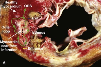
Hemodynamically stable, relatively slow VT that is easily inducible and stable in response to pacing comprises a small minority of re-entrant VTs, especially in the setting of ischemic heart disease. However, when re-entrant VT is present, detailed activation and entrainment mapping can be performed. The goal of both is to identify the critical elements of the re-entrant circuit that are protected by anatomic or functional boundaries (a dense scar or valvular structures) and which would therefore be easiest to successfully target with ablation. The surface ECG recording of VT typically represents the wavefront as it exits the scarred area and begins to depolarize the healthy myocardium. The “exit” is frequently at the end of the most critical portion (isthmus) of the circuit and is located at the border of a scar. However, it is possible for the isthmus to be quite far from the edge of the scar and the wavefront to activate the diseased myocardium for several centimeters before engaging the normal myocardium. Once the wavefront encounters the normal myocardium, it then propagates away from this site to depolarize the rest of the ventricles as well as to complete the depolarization of other portions of the circuit, including the outer scar border (outer loop) and the “entrance” to the isthmus region (Figure 26-1, A). Occasionally, the wavefront may propagate through a path within the scar or area of functional block (inner loop) that is not critical to the maintenance of the circuit.11
During activation mapping, isolated potentials, or abnormal, low-amplitude signals recorded during electrical diastole based on surface ECG analysis, are identified. These recordings are felt to represent depolarization of the aforementioned important portions of the re-entrant circuit, including the most critical (isthmus).8,12,13 Isolated potentials have been found to be present in about half the isthmus sites and represent areas at which radiofrequency (RF) energy application may be most effective in terminating VT.12 However, the isthmus width can range from 6 to 26 mm, and the presence of a broad isthmus may make activation data more difficult to interpret.13 Importantly, isolated diastolic potentials also have been found to be present at bystander sites that are close to, but not participating in, the VT circuit or can even represent far-field activation of tissue remote from the mapping site. Identifying sites critical to the re-entrant circuit can sometimes be better characterized with entrainment mapping (described below) or with pacing from a remote site to dissociate the potential from the VT. The presence of bystander sites as well as the presence of multiple loops of re-entry can often confound analysis.
Entrainment mapping can be performed in hemodynamically tolerated VT that remains stable in response to pacing. Pacing slightly faster than the VT will cause continuous resetting of the re-entry circuit. Sites within the circuit will have a postpacing interval (PPI), or time to return to the site of pacing, within 30 ms of the tachycardia cycle length (TCL). It then follows that the farther away from the circuit that entrainment is attempted, the larger will be the difference between the PPI and the TCL as the time to and from the circuit will need to be added. It should be ensured that the EGM selected for PPI measurement represents local depolarization. The EGM of interest can be very difficult to identify when multiple fractionated signals are present, as is common in the presence of a scar, or when local potentials directly depolarized by pacing are obscured by the pacing artifact. Other major assumptions when interpreting the response to entrainment include the following: (1) Pacing does not alter the path of the circuit or initiate another VT; and (2) conduction time through the circuit is unchanged with entrainment compared with VT. Care should therefore be taken to pace only slightly faster than the TCL, as faster pacing has been shown to alter the VT circuit. Additionally, the presence of antiarrhythmic medications may further decrease conduction velocities during pacing and can potentially confound analysis, particularly when pacing at even modestly faster rates.11
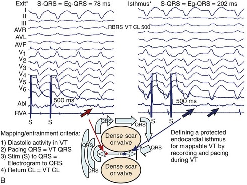
Assuming the conditions described above are met, entrainment mapping can be very helpful in identifying the re-entrant circuit components. Entrainment from all isthmus sites will demonstrate concealed fusion with entrainment or demonstrate capture with pacing, but without a change in QRS morphology of the paced beats compared with VT. At isthmus exit sites, the pacing stimulus to the QRS interval (S-QRS), which represents the conduction time from the pacing site to the re-entry circuit, should be short, or less than 30% of the TCL. At central isthmus sites, the S-QRS should be intermediate, or 31% to 50% of the TCL. At isthmus entrance sites, the S-QRS will be longer, or 51% to 70% of the TCL. At all of these sites, additionally, the S-QRS time should also equal the EGM-to-QRS time during the VT (see Figure 26-1, B). Termination with catheter pressure can occur when mapping in this region suggests a narrow isthmus predisposed to block with the slightest of pertubations.11 The presence of inner-loop or adjacent bystander sites can be confusing, as entrainment also will demonstrate concealed fusion when stimulation is performed at these sights. The S-QRS for the former will be very long (usually >70% of TCL); for the latter, the PPI will not be similar to the TCL, and the S-QRS and the EGM-QRS time will not be equal. At outer loop sites, QRS fusion with entrainment will be manifest because of the propagation of stimulated antidromic wavefronts away from the scar border in addition to within the VT circuit. Evidence that the site is within the VT circuit is that the PPI will approximate the TCL. If the scar border along this portion of the circuit is in continuity with healthier myocardium, the width of this circuit portion may be quite broad; termination with either focal ablation or catheter trauma is thus often less successful (<10%) at these sites.
Mapping Strategies: Hemodynamically Unstable Ventricular Tachycardia
Sinus Rhythm Voltage Map
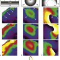
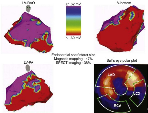
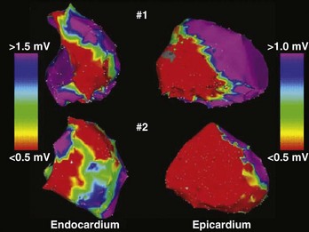
A detailed substrate and voltage map should be created, with efforts initially focused on areas of known infarction or scarring on the basis of prior imaging. The endocardial extent of the anatomic abnormality has been well characterized using bipolar voltage criteria of 1.5 to 2.0 mV; this helps identify normal signal amplitude recorded from the LV endocardium using a commercially available electroanatomic mapping system (CARTO, Biosense Webster, Inc., Diamond Bar, CA) with a 4-mm electrode tip mapping catheter.8 Low-voltage areas of the endocardium typically serve as the arrhythmia substrate for most patients with sustained VT. Thus, a color range corresponding to endocardial bipolar voltages of 0.5 to 1.5 mV will highlight areas of densely scarred myocardium or aneurysm (<0.5 mV), border zone of a scar (0.5 to <1.5mV), and healthy myocardium (>1.5 mV). It is important to note that the extent of an endocardial scar identified on voltage mapping often will exceed that observed on thallium imaging in patients with extensive septal involvement. This phenomenon may be caused by lower sensitivity of the thallium imaging in identifying subendocardial versus transmural infarction (Figure 26-2).
Late Potential Mapping and Ablation
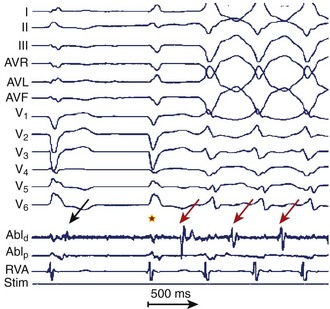
Frequently, double potentials, late potentials, or both during sinus rhythm can be observed on bipolar recordings within or at the borders of a scar that has been delineated by voltage mapping. Late potentials are defined as distinct bipolar EGMs that are inscribed after the end of the surface QRS complex and separated from the major initial component of the local ventricular EGM by an isoelectric interval. They are felt to represent delayed activation within the diseased myocardium and have often been found at critical sites within re-entrant VT circuits.13 Investigators have shown that these potentials are found within 89% of isthmus sites, 57% of entrance, and 20% of exit sites (Figure 26-3).13 This strategy, combined with voltage mapping, identifies appropriate ablation targets and provides a more refined substrate-based approach for VT ablation.
Pacemapping
In conjunction with a detailed voltage map and available VT morphologies from 12-lead surface ECGs or from ICD electrograms, pacemapping is used to approximate the VT exit site for VT that cannot be characterized by activation or entrainment mapping because of hemodynamic instability.8,13 The procedure involves pacing at different ventricular sites along the border of the scar during sinus rhythm to identify site(s) at which the paced QRS morphology mimics that observed during VT. When using pacemapping to localize the VT exit site, certain important limitations must be recognized. The paced QRS morphology may not accurately reflect the site of origin of the VT and may not identify an appropriate site for VT ablation. Bidirectional conduction from the pacing site may not mimic the unidirectional wavefront of activation associated with the VT circuit. Furthermore, the output used to capture with pacing, especially if high, can influence the pattern of ventricular activation and produce a different QRS morphology in sinus rhythm because of an increase in the size of the virtual electrode; this will differ from that during VT even when pacing within a critical site of the VT circuit. Nevertheless, pacemapping can approximate the exit site of the VT circuit in most patients and is a generally accepted method for mapping when more detailed options are limited because of poor hemodynamic intolerance or noninducibility of VT.
Conducting Channels
Many slower, more mappable VTs demonstrate conduction through densely infarcted myocardium (<0.5 mV). In these cases, viable channels of the conducting myocardium may be identified by decreasing the color range such that narrow channels of larger voltage surrounded by areas of extremely low voltage can be visualized.13 Such channels also can be identified during RV pacing in the absence of ongoing VT.8 Fractionated EGMs, with isolated delayed components, multiple components, or both are often seen at isthmus sites; however, these low-amplitude signals may be obscured in sinus rhythm because of depolarization of the surrounding larger mass of the more normal myocardium. Changing the direction of depolarization, for instance, with pacing, has been observed to better elucidate these signals and potential channels of conduction. RV apical pacing has been used for this purpose. While the identification of conducting channels in conjunction with other methods can be useful, it is often not specific enough to be the sole mapping guide.8
Noncontact Mapping
A final approach to mapping poorly tolerated or otherwise unmappable VT is via noncontact mapping using a multi-electrode system. The currently available system is a woven braid of 64 wires 0.003 inches in diameter mounted on a 7.6-mL balloon on a 9-Fr catheter. Each wire has a 0.025-inch break in insulation, producing noncontact unipolar electrodes. It allows display of more than 3300 mathematically derived unipolar EGMs via inverse solution to Laplace’s equation.14 Good correlation has been observed between EGMs computed using the noncontact balloon and those obtained simultaneously by direct catheter contact, with reasonable results reported in limited clinical experiences to date.14 However, the system is currently somewhat cumbersome to use, as it requires a customized amplifier system and a Silicon Graphics workstation to run the software. Other limitations include (1) potential need for contact mapping in areas that are inaccessible by the balloon system because of low-amplitude signals or excessive (>34 mm) distance from the balloon to the endocardial surface and (2) easy loss of position of the balloon in patients with normal LV function in the setting of recommended retrograde aortic positioning.
Epicardial Ventricular Tachycardia Mapping
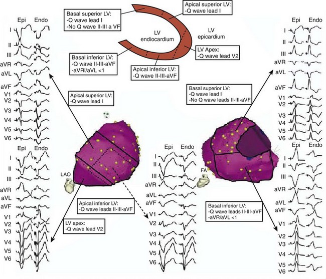
Features that may indicate the need for epicardial mapping and ablation can be apparent on the surface 12-lead ECG recorded during VT.15,16 These include the presence of a particularly wide-QRS VT with a slurred initial aspect of the QRS complex. A Q wave in lead I is a particularly sensitive characteristic for identifying an epicardial VT site of origin in patients with nonischemic cardiomyopathy. If it is present and if Q waves are absent in the inferior leads, a basal and superolateral epicardial focus is suggested (Figure 26-4). The details of epicardial mapping and ablation are discussed in later chapters.
Unique Considerations for Assessment in Specific Types of Ventricular Tachycardia
Ventricular Tachycardia with Nonischemic Left Ventricular Disease
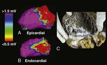
Patients with VT in the setting of nonischemic LV cardiomyopathy typically have, in addition to depressed LV function, low-voltage areas consistent with the scar frequently in perivalvular distribution, and often with epicardial involvement (Figure 26-5). The mechanism of VT in this disease substrate is usually re-entry.8 Intracardiac EGMs in scarred regions frequently are abnormal and fractionated, and the overall surface, signal-averaged ECG is abnormal.3 Mapping and ablation strategies are as outlined above for typical re-entrant VT caused by ischemic heart disease.
Arrhythmogenic Right Ventricular Cardiomyopathy or Dysplasia
Patients with arrhythmogenic right ventricular cardiomyopathy or dysplasia (ARVC/D) have a progressive disorder with autosomal-dominant inheritance that is marked by fibro-fatty infiltration of the normal myocardium. This process primarily involves the RV but may also involve the LV. It can begin with localized dysplasia, which is recognized only on postmortem examination in patients with documented VT. In a pathologic condition, the process appears to first affect the epicardium, spreading gradually inward through the myocardium. The most commonly affected areas are the RV infundibulum, the inferoposterior subtricuspid region, and, less commonly, the RV apex marked by aneurysm formation. Of note, the location of most abnormal EGMs and the source of VT is perivalvular (pulmonic, tricuspid, or both). The prevalence is estimated to be 1:5000 to 1:10,000 in the general population, and it accounts for 5% of SCD events in adults younger than 35 years and 22% of SCD in athletes. The clinical course is marked by progressive RV dysfunction that may predispose to VT, VF, or both, and RV heart failure. Possible infectious and immunologic causes have been postulated as triggering mechanisms acting on a genetically defined desmosomal protein abnormality, given that as many as 80% of hearts affected by ARVC/D at autopsy have inflammatory infiltrates. When ventricular arrhythmias occur, they usually are re-entrant and of multiple LBBB morphologies, reflecting a diffusely affected right ventricle.16 VT with an epicardial site of origin is suggested by 12-lead ECG characteristics of a Q or a QS in the inferior leads for inferiorly exiting sites or in lead V2 for VTs exiting from the anterior RV.16 Successful ablation of epicardial VT enhances the overall success of VT ablation in this setting (Figure 26-6).16 Ablative therapy should be considered before the administration of amiodarone in this young patient population and to treat patients who experience ICD shocks.16
Hypertrophic Cardiomyopathy
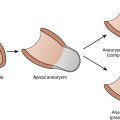
Hypertrophic cardiomyopathy (HCM) is an autosomal-dominant inherited disorder of sarcomeres, with variable penetrance and expression, which leads to myocyte hypertrophy and disarray and varying degrees of usually asymmetric LV septal hypertrophy. The risk of SCD in this population has long been recognized, and ICD implantation for primary and secondary prevention has increased in the last several years. High-risk characteristics that justify ICD implantation in either setting include prior cardiac arrest; familial sudden death; massive left ventricular hypertrophy (LVH), or maximum LV wall thickness 30 mm or greater; syncope; multiple episodes of recurrent nonsustained VT; hypotension during exercise stress testing; end-stage disease, marked by systolic dysfunction often with LV remodeling and dilation; presence of LV apical aneurysm; and prior alcohol septal ablation.17 The last two subgroups have become increasingly recognized for their higher risk of repetitive episodes of MMVT. Patients with HCM and apical aneurysm comprise about 2% of an HCM cohort. Their higher incidence of MMVT is thought to be caused by focal myocardial scarring of the distal LV, which arises from chronically abnormal strain at the junction of the apical aneurysm and the rest of the myocardium. The mechanism of VT is re-entry, and VT ablation that targets the apical endocardial and epicardial circuits has proven successful.17 Residual scar from alcohol septal ablation can be substantial, occupying about 10% of the total LV mass, and it has also been shown to be arrhythmogenic in some HCM patients. Some series have reported a fourfold increased risk of appropriate ICD shocks in these patients, compared with those who underwent surgical myomectomy for the treatment of outflow obstruction.17
Idiopathic Ventricular Tachycardia
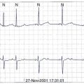
Idiopathic VT occurs in otherwise normal hearts, has a very benign prognosis, and accounts for about 10% to 15% of clinical VTs.18 The most common type generally originates from the RVOT and has also been known as repetitive monomorphic VT. Its mechanism is believed to be triggered, and the typical clinical presentation is with salvos of nonsustained MMVT in the setting of caffeine, emotional stress, or exercise.5 In the electrophysiological laboratory, the arrhythmia can often be provoked with catecholamine infusion or with burst pacing in the atrium or ventricle and can often be terminated with adenosine infusion.3 The typical pattern of the VT observed on the 12-lead ECG is LBBB with large, monophasic R waves in the inferior leads. Most of these VTs arise from the septal-anterior aspect of the RVOT from a narrow segment just under the pulmonic valve. Less frequently, they may originate from the free wall or posterior-septal aspect of the superior RVOT or the LV.
A mapping scheme based on 12-lead ECG characteristics has been developed to assist with localization in the RVOT before ablation (Figure 26-7, A).19 Septal RVOT VTs will tend to have taller and narrower inferior, monophasic R waves and a slightly earlier precordial transition compared with corresponding free-wall RVOT VTs; free-wall VTs often will have notched R waves in the inferior leads. To distinguish between anterior RVOT sites and posterior RVOT sites, the most discriminating lead to assess is lead I. Anterior RVOT VTs will often have a predominantly negative QRS complex (qs) in lead I, whereas posteriorly originating VTs will be more positive, with a small r. VTs originating between the two will accordingly have a more intermediate or biphasic to multi-phasic complex (qr/rs pattern) in lead I with net isoelectric polarity.
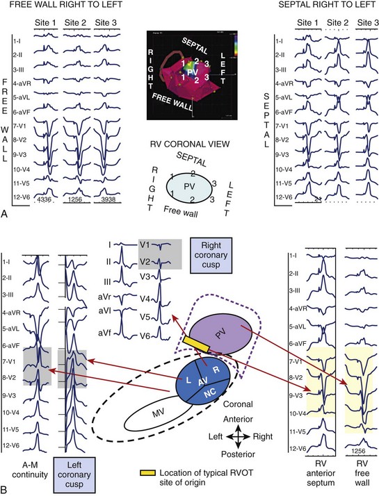
Occasionally, idiopathic VT can originate from sites above the pulmonic valve and in the LVOT and surrounding areas, including the AV cusps.20 ECG criteria have also been developed to distinguish VTs originating in the LVOT from those originating in the RVOT. Surface ECG clues that indicate an LVOT versus RVOT site of origin include (1) RBBB and tall, monophasic inferior R waves with a dominant R wave in V1 and lack of precordial transition, with or without a late-appearing S wave in lead V6; or (2) LBBB and inferiorly directed axis with an earlier precordial R-wave transition than would be expected in RVOT VT (usually by V2) (see Figure 26-7, B). Additional criteria to localize VTs within the basal LV region include (1) QRS duration and (2) R-wave in V1, both of which help distinguish between medial versus lateral sites.20
Finally, there are surface ECG clues that have been developed to further elucidate the VT site of origin from the aortic valve cusps as opposed to the RVOT.20 The majority of these VTs originate from the left coronary cusp (LCC), especially the junction between the right and left cusps. In lead V1, a multi-phasic M or W pattern may be observed for VT arising from the LCC or a distinctive qr pattern if originating from the anterior mitral cusp (AMC); overall, the R-wave duration and the R- or S-wave amplitude observed in cusp VT compared with RVOT VT are greater. In lead I, often a terminal S is present for VT originating from the LCC or AMC. The precordial transition is earlier overall than in the RVOT.
Idiopathic fascicular VT is another major subset of idiopathic VT. It typically originates from the left posterior fascicle and involves the LV inferior septum from the base to the apex, with a superficial endocardial Purkinje network participating in what largely is felt to be a re-entrant circuit, although some debate exists as to whether mechanism is triggered or abnormal automaticity in selected patients.18 The arrhythmia tends to be uniquely verapamil sensitive, and, in the electrophysiological laboratory, can be induced with PES and occasionally with rapid atrial or ventricular burst pacing. The VT is not typically induced with isoproterenol infusion, but the drug may potentiate initiation with programmed stimulation. The morphology of the VT is typically RBBB with left-superior axis deviation (consistent with a posterior fascicular origin). Mapping during VT is preferable, for the purposes of confirming the diagnosis and ablation. Areas where the earliest pre-QRS Purkinje potential is seen have been targeted for ablation with successful elimination of the arrhythmia. Even when sustained VT cannot be induced, a mapping strategy in sinus rhythm, based on the assumption of a sizable macro–re-entrant circuit along the septum, can be undertaken. The area along the mid-septal LV endocardium can be mapped to identify Purkinje potentials. An ablation line is then drawn from the inferior margin to the mid-septum.18
Key References
Bazan V, Gerstenfeld EP, Garcia F, et al. Site-specific twelve-lead ECG features to identify an epicardial origin for left ventricular tachycardia in the absence of myocardial infarction. Heart Rhythm. 2007;4:1403-1410.
Brugada P, Brugada J, Mont L, et al. A new approach to the differential diagnosis of a regular tachycardia with a wide QRS complex. Circulation. 1991;83:1649-1659.
Dixit S, Gerstenfeld EP, Callans DJ, Marchlinski FE. Electrocardiographic patterns of superior right ventricular outflow tract tachycardias: Distinguishing septal and free-wall sites of origin. J Cardiovasc Electrophysiol. 2003;14:1-7.
Garcia F, Bazan V, Zado ES, et al. Epicardial substrate and outcome with epicardial ablation of ventricular tachycardia in arrhythmogenic right ventricular cardiomyopathy/dysplasia. Circulation. 2009;120:366-375.
Henkel DM, Witt BJ, Gersh BJ, et al. Ventricular arrhythmias after acute myocardial infarction: A 20-year community study. Am J Cardiol. 2006;151:806-812.
Hsia HH, Lin D, Sauer WH, et al. Relationship of late potentials to the ventricular tachycardia circuit defined by entrainment. J Interv Card Electrophysiol. 2009;26(1):21-29.
Jerosch-Herold M, Kwong RY. Optimal imaging strategies to assess coronary blood flow and risk for patients with coronary artery disease. Curr Opin Cardiol. 2008;23:599-606.
Josephson ME. Clinical cardiac electrophysiology: Techniques and interpretations, ed 4. Philadelphia: Lippincott Williams & Wilkins; 2008.
Kocovic DZ, Harada T, Friedman PL, Stevenson WG. Characteristics of electrograms recorded at re-entry circuit sites and bystanders during ventricular tachycardia after myocardial infarction. J Am Coll Cardiol. 1999;34:381-388.
Lim KK, Maron BJ, Knight BP. Successful catheter ablation of hemodynamically unstable monomorphic ventricular tachycardia in a patient with hypertrophic cardiomyopathy and apical aneurysm. J Cardiovasc Electrophysiol. 2009;20:445-447.
Lin D, Hsia HH, Gerstenfeld EP, et al. Idiopathic fascicular left ventricular tachycardia: Linear ablation lesion strategy for noninducible or nonsustained tachycardia. Heart Rhythm. 2005;2:934-939.
Lin D, Ilkhanoff L, Gerstenfeld EP, et al. Twelve-lead electrocardiographic characteristics of the aortic cusp region guided by intracardiac echocardiography and electroanatomic mapping. Heart Rhythm. 2008;5:663-669.
Marchlinski FE. Ventricular tachycardia: Clinical presentation, course, and therapy. In: Zipes D, Jalife J, editors. Cardiac electrophysiology: From cell to bedside. Philadelphia: Saunders, 1995.
Marchlinski FE, Garcia F, Siadatan A, et al. Ventricular tachycardia/ventricular fibrillation in the setting of ischemic heart disease. J Cardiovasc Electrophysiol. 2005;16(Suppl 1):S59-S70.
Moss AJ, Greenberg H, Case RB, et al. Long-term clinical course of patients after termination of ventricular tachyarrhythmia by an implanted defibrillator. Circulation. 2004;110:3760-3765.
Nazarian S, Roguin A, Zviman MM, et al. Clinical utility and safety of a protocol for noncardiac and cardiac magnetic resonance imaging of patients with permanent pacemakers and implantable-cardioverter defibrillators at 1.5 Tesla. Circulation. 2006;114:1277-1284.
Rajappan K, Schilling RJ. Non-contact mapping in the treatment of ventricular tachycardia after myocardial infarction. J Interv Card Electrophysiol. 2007;19:9-18.
Riley MP, Marchlinski FE. ECG clues for diagnosing ventricular tachycardia mechanism. J Cardiovasc Electrophysiol. 2008;19:224-229.
Stevenson WG, Friedman PL, Sager PT, et al. Exploring postinfarction reentrant tachycardia with entrainment mapping. J Am Coll Cardiol. 1997;29:1180-1189.
Zipes D, Camm A, Borggrefe M, et al. ACC/AHA/ESC 2006 guidelines for management of patients with ventricular arrhythmias and the prevention of sudden cardiac death: A report of the American College of Cardiology/American Heart Association Task Force and the European Society of Cardiology Committee for Practice Guidelines (Writing Committee to Develop Guidelines for Management of Patients with Ventricular Arrhythmias and the Prevention of Sudden Cardiac Death). J Am Coll Cardiol. 2006;48:e247-e346.
1 Zipes D, Camm A, Borggrefe M, et al. ACC/AHA/ESC 2006 guidelines for management of patients with ventricular arrhythmias and the prevention of sudden cardiac death: A report of the American College of Cardiology/American Heart Association Task Force and the European Society of Cardiology Committee for Practice Guidelines (Writing Committee to Develop Guidelines for Management of Patients with Ventricular Arrhythmias and the Prevention of Sudden Cardiac Death). J Am Coll Cardiol. 2006;48:e247-346.
2 Henkel DM, Witt BJ, Gersh BJ, et al. Ventricular arrhythmias after acute myocardial infarction: A 20-year community study. Am J Cardiol. 2006;151:806-812.
3 Kempf FCJr, Josephson ME. Cardiac arrest recorded on ambulatory electrocardiograms. Am J Cardiol. 1984;53:1577-1582.
4 Marchlinski FE. Ventricular tachycardia: Clinical presentation, course, and therapy. In: Zipes D, Jalife J, editors. Cardiac electrophysiology: From cell to bedside. Philadelphia: Saunders, 1995.
5 Moss AJ, Greenberg H, Case RB, et al. Long-term clinical course of patients after termination of ventricular tachyarrhythmia by an implanted defibrillator. Circulation. 2004;110:3760-3765.
6 Riley MP, Marchlinski FE. ECG clues for diagnosing ventricular tachycardia mechanism. J Cardiovasc Electrophysiol. 2008;19:224-229.
7 Wieland JM, Marchlinski FE. Electrocardiographic response of digoxin-toxic fascicular tachycardia to Fab fragments: Implications for tachycardia mechanism. Pacing Clin Electrophysiol. 1986;9:727-738.
8 Lerman BB, Stein K, Engelstein ED, et al. Mechanism of repetitive monomorphic ventricular tachycardia. Circulation. 1995;92:421-429.
9 El-Sheriff N, Gough WB, Zeiler RH, Mehra R. Triggered ventricular rhythms in 1-day-old myocardial infarction in the dog. Circ Res. 1983;52:566-579.
10 Brugada P, Brugada J, Mont L, et al. A new approach to the differential diagnosis of a regular tachycardia with a wide QRS complex. Circulation. 1991;83:1649-1659.
11 Wellens HJ, Bar FW, Lie KI. The value of the electrocardiogram in the differential diagnosis of a tachycardia with a widened QRS complex. Am J Med. 1978;64:27-33.
12 Josephson ME, Horowitz LN, Waxman HL, et al. Sustained ventricular tachycardia: Role of the 12-lead electrocardiogram in localizing site of origin. Circulation. 1981;64:257-272.
13 Miller JM, Marchlinski FE, Buxton AE, Josephson ME. Relationship between the 12-lead electrocardiogram during ventricular tachycardia and endocardial site of origin in patients with coronary artery disease. Circulation. 1988;77:759-766.
14 Patel VV, Rho RW, Gerstenfeld EP, et al. Right bundle-branch block ventricular tachycardias: Septal versus lateral ventricular origin based on activation time to the right ventricular apex. Circulation. 2004;110:2582-2587.
15 Jerosch-Herold M, Kwong RY. Optimal imaging strategies to assess coronary blood flow and risk for patients with coronary artery disease. Curr Opin Cardiol. 2008;23:599-606.
16 Nazarian S, Roguin A, Zviman MM, et al. Clinical utility and safety of a protocol for noncardiac and cardiac magnetic resonance imaging of patients with permanent pacemakers and implantable-cardioverter defibrillators at 1.5 Tesla. Circulation. 2006;114:1277-1284.
17 Wellens HJ. Value and limitations of programmed electrical stimulation of the heart in the study and treatment of tachycardias. Circulation. 1978;57:845-853.
18 Josephson ME. Clinical cardiac electrophysiology: Techniques and interpretations, ed 4. Philadelphia: Lippincott Williams & Wilkins; 2008.
19 Buxton AE, Waxman HL, Marchlinski FE, et al. Role of triple extrastimuli during electrophysiologic study of patients with documented sustained ventricular arrhythmias. Circulation. 1984;69:532-540.
20 Buxton AE, Waxman HL, Marchlinski FE, et al. Right ventricular tachycardia: Clinical and electrophysiologic characteristics. Circulation. 1983;68:917-927.