Chapter 27 Electrophysiological Evaluation of Atrial Tachycardia and Atrial Flutter
Atrial Tachycardia
Focal atrial tachycardia (AT) is the least common type of supraventricular tachycardia (SVT), comprising approximately 10% to 15% of patients referred for electrophysiological evaluation of SVT.1 Possible mechanisms include triggered activity, enhanced automaticity, or micro–re-entry. AT has been defined as rhythmic atrial activation spreading centrifugally from a focal area less than 2 cm.2 Although no difference in prevalence exists between genders and any age group may be affected, some evidence suggests that older patients are more likely to have multiple foci from the right atrium that have a nonautomatic mechanism and are recurrent after catheter ablation.3
It is well recognized that focal ATs are not randomly distributed but, rather, congregate around defined anatomic locations. In the right atrium, the most common site is along the crista terminalis (CT), with foci also clustering around the tricuspid annulus, coronary sinus os, right atrial appendage, perinodal region, and inter-atrial septum.4–7 In the left atrium, the pulmonary veins provide the majority of foci, with the mitral annulus, left septum, left atrial appendage, and noncoronary aortic cusp being other potential locations.8–12 Knowledge of this clustering is of great assistance to the electrophysiologist while attempting to localize the likely site of origin during an electrophysiology study.
Indications for Referral to the Electrophysiology Laboratory
Although focal atrial ectopy is common, it is rarely symptomatic. In contrast, frequent ectopy and sustained tachycardia are often symptomatic and prompt patients to present to the clinician for assessment. Incessant AT may also induce left ventricular dysfunction, which can resolve after curative ablation3 Focal AT tends to respond poorly to pharmacologic therapy, making catheter ablation an increasingly used procedure. The American College of Cardiology, the American Heart Association Task Force on Practice Guidelines, and the European Society of Cardiology Committee (ACC/AHA/ESC) consensus guidelines published in 2003 provide a class I recommendation for catheter ablation of focal AT in patients with incessant tachycardia or recurrent symptoms.1
Importance of Surface Electrocardiogram and P-Wave Morphology
The surface electrocardiogram (ECG) can be a useful guide to the likely anatomic site of origin for focal AT. This information can then be used by the clinician during intracardiac electrophysiological mapping to target specific areas. Kistler et al published an algorithm for the localization of atrial tachycardias based on the surface ECG P-wave morphology (PWM) that was able to identify the correct anatomic location with an accuracy of 93%.13 PWM is typically described as positive, negative, isoelectric, bifid, or biphasic (positive-negative or negative-positive). When analyzing PWM, it is important to ensure that the preceding T wave is not superimposed. Spontaneous ventricular ectopic beats, programmed ventricular extrastimuli, or vagal maneuvers such as the Valsalva maneuver or carotid sinus massage may assist with separation of the T wave and P wave. Distinguishing left and right atrial foci is of importance when planning a procedure, as trans-septal access may be anticipated on the basis of PWM. A left-sided focus is suggested by a positive P wave in V1 and a negative P wave in I and aVL.
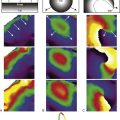
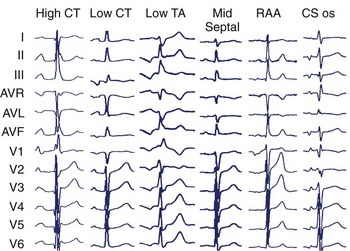
Specific anatomic sites have characteristic PWMs. Examples of right atrial foci PWMs are shown in Figure 27-1. Foci from the crista terminalis account for two thirds of right atrial foci.4 The characteristic PWM is similar to the sinus rhythm being positive-negative in V1, positive in I and II, and negative in aVR.13 Foci from the tricuspid annulus (TA) tend to have a negative P wave in V1 and V2, with superior locations displaying positive PWM in II, III, and aVF and inferior locations displaying negative PWM in the inferior leads. Right atrial appendage locations have indistinguishable PWM to superior TA locations. Focal ATs from the coronary sinus (CS) ostium are characterized by deeply negative PWM in the inferior leads, positive in aVL and aVR, and isoelectric-positive or negative-positive in V1. Septal locations may have variable PWM.
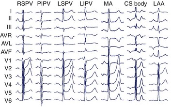
In the left atrium, pulmonary veins are the most common sources of foci. Representative left atrial PWMs are shown in Figure 27-2. V1 is typically positive across the chest leads, aVR is negative, and aVL is isoelectric or negative.13 Right and left superior pulmonary veins (PVs) tend to have positive PWM in the inferior leads; conversely, right and left inferior PVs have low-amplitude or inverted P waves inferiorly. Left-sided veins exhibit a broader notched P wave in V1 and in the inferior leads, compared with right-sided veins. The left atrial appendage (LAA) foci have a PWM similar to that of the left superior PV, although a deeply negative P wave in lead I, particularly in the setting of incessant tachycardia, is a strong clue that this may be an LAA focus.11 Mitral annular locations near the aorto-mitral continuity tend to have biphasic negative-positive PWM in V1 and isoelectric or negative PWM in aVL. More recently, focal AT from the noncoronary cusp of the aortic valve has been described, with a PWM similar to the mitral annular location.9 A positive P wave in leads I and aVL may help differentiate this site from the mitral annular location.
Confirming the Diagnosis
The diagnosis of focal AT can usually be made on the surface ECG. Important differential diagnoses include sinus tachycardia (ST), atrioventricular node re-entry tachycardia (AVNRT), atrioventricular reciprocating tachycardia (AVRT), and macro–re-entrant AT. On the surface ECG, AT typically manifests with a long R-P interval. However, at rapid rates, decremental AV nodal conduction may result in an apparent short R-P tachycardia. While both typical AVNRT and AVRT characteristically present with a short R-P interval, this relationship is fixed or “hooked.” In focal AT, a variable or unhooked R-P relationship may be present. When clearly not of sinus origin, PWM can be used to distinguish AT from ST. However, AT arising from the superior crista terminalis may have a morphology indistinguishable from that of ST. Indeed, these tachycardias were previously termed “sinus node re-entry.” The presence of a “warm-up” over three to four beats at onset and “cool-down” over three to four beats at termination supports a diagnosis of AT over ST, which typically accelerates and decelerates over more than 30 seconds.14 Macro–re-entrant AT generally manifests with an undulating baseline and no clear isoelectric segment (which is usually seen in focal AT). It is important to note that focal tachycardias at very short cycle lengths may show no isoelectric baseline and mimic macro–re-entry. Similarly, focal tachycardia in atria with scarring and slowed conduction may also show an undulating baseline because of circuitous propagation away from the focus.
Confirming the Diagnosis Using Intracardiac Recordings and Pacing Maneuvers
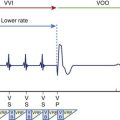
Although the surface ECG may have provided a likely diagnosis, intracardiac recordings and pacing maneuvers during tachycardia are often required to exclude alternative diagnoses. On examination of the intracardiac recordings, the relationship between the ventricular and atrial electrograms (VA relationship) is seen to be fixed or “hooked” in AVNRT and AVRT but variable in AT. Various pacing maneuvers may facilitate the observation of VA unhooking. Following termination of the atrial overdrive pacing at a cycle length that is just below the tachycardia cycle length, the VA relationship remains fixed in both AVNRT and AVRT; however, VA unhooking is observed when the mechanism is focal AT.15 The response after entrainment of the tachycardia by ventricular pacing (confirmed by acceleration of the atrial rate to the pacing rate) is also helpful. A “V-A-V” response is characteristic of AVRT or AVNRT, and a “V-A-A-V” response is observed in AT. In addition, AT may be excluded if termination of the tachycardia occurred without atrial depolarization during burst ventricular pacing at a 200- to 250-ms cycle length for three to six beats. Demonstration of entrainment from “within the circuit” (Post-pacing interval—Tachycardia cycle length [PPI — TCL] <20 ms) from two sites more than 2 cm apart or the ability to record activity throughout the entire tachycardia cycle length are both definitive for macro–re-entrant AT.1
Conventional Mapping
The hallmark of focal AT is the identification of a focal site of early activation with centrifugal spread on endocardial mapping. A local activation time of more than 20 to 30 ms before the surface ECG P-wave onset indicates a potential site for successful ablation.16 Attempts to define the clear P-wave onset (using pacing maneuvers or adenosine if it cannot be seen) are important. The P-wave onset can then be referenced to a stable intracardiac reference point such as the proximal CS bipole.
Multipolar catheters (20-pole TA or CT) may act as a guide to the focal origin and may also be helpful to rapidly recognize any change in the mechanism or the site of origin of the tachycardia. Pace mapping may also be used to complement activation sequence mapping. The endocardial activation sequence during pacing from various sites that has been mapped by using a catheter can be compared with the spontaneous activation sequence seen during tachycardia.17
Electrogram Characteristics of Successful Sites
Several groups have reported on the presence of electrogram fractionation recorded from ablation catheters at the sites of successful ablation. However, this finding is not universal and may be specific to certain anatomic regions only (e.g., electrograms for focal AT arising from the CT commonly show fractionation, but those at the tricuspid and mitral annulus usually do not).16 It is hypothesized that these fractionated signals represent underlying slow conduction caused by impaired intercellular coupling, which results in the potential for micro–re-entry.
Many electrophysiological laboratories use the unipolar electrogram at the ablation catheter tip to identify the characteristic QS pattern of a successful ablation site.18
The termination of sustained tachycardia with pressure from an intracardiac catheter has been reported to improve on the specificity and positive predictive value of identifying an AT focus.19 In practice, if ablation is performed at a site of termination by catheter pressure, it may be uncertain whether ablation has been successful or if mechanical pressure has simply caused transient stunning of the focus. In the experience of the authors, ablation at the site of mechanical termination carries a relatively high risk of recurrence.
Atrial pacing during tachycardia at a rate just below the tachycardia cycle length has been used to identify the site of focal origin.20 In theory, at the site of origin the PPI-TCL should equal 0 ms. In a recent study, the postpacing interval minus the tachycardia cycle length was 11 ± 8 ms at sites of successful ablation.
Three-Dimensional Electroanatomic Mapping Systems
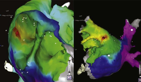
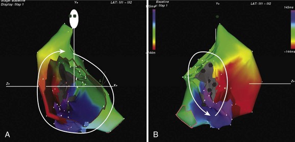
The development of three-dimensional mapping systems has significantly improved the ability of clinicians to successfully locate and ablate foci. Both the CARTO (Biosense Webster, Johnson & Johnson, Diamond Bar, CA) and NavX (Diag Corporation, Minnetonka, MN) systems use complex algorithms for the registration of a mapping/ablation catheter position in three-dimensional space relative to a fiducial point. This allows the construction of three-dimensional chamber geometry with activation sequence mapping (traditionally color coded). In addition, these data can be superimposed onto images of the atrium taken by either computed tomography or magnetic resonance imaging (MRI) scans allowing detailed and accurate correlation of the atrial anatomy with intracardiac electrograms (for an example, see Figure 27-3). Several groups have verified the usefulness of these systems in locating and ablating AT foci.16 Despite these advantages and the potential for a reduction in radiation exposure because of lower fluoroscopy times, these mapping systems still require frequent ectopy or sustained tachycardia for effective mapping.
Ablation
Standard radiofrequency ablation catheters may be used in the vast majority of cases; irrigated tip catheters may be useful in areas of the atrium with slow blood flow, such as trabeculated areas and within the CS. Cryoablation is an alternative energy source with the advantage of reversibility at –30° C. Moreover, once applied at this temperature, the catheter remains firmly adherent to the underlying tissue, providing excellent catheter stability. These attributes make this energy source an ideal choice for perinodal foci, where permanent AV-nodal block can be avoided by assessing for block with a reversible lesion before applying a full lesion at –80° C (−112° F).21 Long vascular sheaths may assist with catheter direction, contact, and stability.
Overall, the success rates for catheter ablation are excellent; reported series cite cure rates between 69% and 100%.16 On the basis of pooled data, recurrence was predicted to be approximately 7%.3 Factors predicting recurrence in this analysis included male gender, multiple foci, older age, and coexisting cardiac pathology. Right atrial foci were predicted to have higher success rates.
Macro–Re-entrant Atrial Tachycardia
Definitions
Macro–re-entrant AT is a broad term that encompasses both typical (cavo-tricuspid isthmus [CTI])–dependent) atrial flutter and atypical (non–CTI-dependent) atrial flutter (or macro–re-entrant tachycardias). They have in common the classic requirements for re-entry: obstacles which create areas of anatomic or functional conduction block around which two pathways may conduct; unidirectional block in one pathway; and areas of slow conduction creating an excitable gap. Classic entrainment identifies areas “within” the circuit and should be demonstrable by pacing from at least two sites more than 2 cm apart and finding a postpacing interval minus tachycardia cycle length of 20 ms or less. Identification of a critical isthmus by demonstration of concealment (whether on the surface or by intracardiac recordings) is fraught with problems and is of limited practical utility in the atrium.2
Typical Atrial Flutter
Typical atrial flutter is the most common form of macro–re-entrant AT and typically has a cycle length of approximately 200 ms. This may be considerably longer (ranging up to 300 ms) in the presence of atrial disease with atrial enlargement and conduction slowing, particularly in the presence of antiarrhythmic agents which slow conduction. Its prevalence is estimated at 5 per 100,000 in those younger than 50 years and increases with age to almost 600 per 100,000 among those older than 80 years.22 Men are affected 2.5 times more frequently than are women.22 The anatomic boundaries of this circuit are well known and are described elsewhere in this text (see Chapter 44).
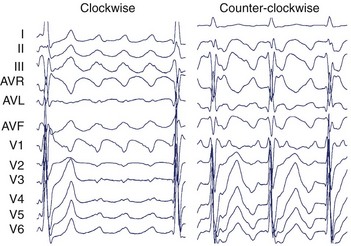
The surface ECG of typical CCW flutter is characterized by isoelectric-positive P waves in V1 transitioning to negative across the precordium (Figure 27-4). Flutter waves in the inferior leads are generally deeply inverted and have a variable secondary upright component timing with activation of the atrial free wall from superior to inferior. When this secondary component is prominent, it may be difficult to determine whether the flutter wave is predominantly “up” or “down.” The ECG appearance of clockwise typical CTI-dependent flutter is more variable. Commonly, V1 is broad and negative with notching, transitioning to positive across the precordium; the inferior leads are usually broad and positive with notching (see Figure 27-4).23 Other macro–re-entrant circuits have variable ECG characteristics and, as such, detailed intracardiac electrophysiological studies are required for accurate anatomic localization.
Indications for Catheter Ablation
In general, pharmacologic therapy for atrial flutter is either targeted at ventricular rate control using AV-nodal blocking agents (such as β-blockers and cardiac-selective calcium channel blockers) or maintenance of sinus rhythm with class I and III antiarrhythmic drugs. Both these approaches have limitations; the overall maintenance of sinus rhythm on antiarrhythmic drugs is between 36% and 73%.1 Evidence from a randomized prospective study of catheter ablation versus medical therapy demonstrated sinus rhythm at 21 ± 11 months in 80% of patients with catheter ablation, compared with 36% for those on antiarrhythmic drugs.24 In addition, the ablation group had significantly fewer hospital admissions and episodes of atrial fibrillation (AF). For patients with coexisting AF, in whom flutter is the dominant rhythm, catheter ablation has been shown to reduce the burden of flutter and assist pharmacologic control of AF.1 The ACC/AHA/ESC consensus guidelines provide a class I recommendation for catheter ablation of atrial flutter if it is recurrent, is poorly tolerated, or re-emerges after class I antiarrhythmic or amiodarone therapy.1 A class IIa recommendation is given for atypical flutter after failure of antiarrhythmic medications.
Anatomy of the Cavo-Tricuspid Isthmus
The anatomy of the CTI has been described as a quadrilateral structure bounded anteriorly by the TA and posteriorly by the eustachian ridge. It is limited laterally by the terminal insertion of the crista terminalis and medially by the CS ostium and the thebesian valve. Trabeculae within the CTI are formed by pectinate extensions of the crista terminalis and intervening connective tissue.25–27 The thicknesses of CTI trabeculae and the eustachian ridge vary markedly, being largely fibrous tissue with sparse muscle fibers in some patients and deeply trabeculated with thick muscle bundles and intervening pouches or recesses in others.28 It is this variability in anatomy that determines the ease or difficulty of ablation. The CTI tends to be wider more laterally than in the middle or septal regions. The septal aspect of the CTI lies close to the posterior extensions of the AV node and to the middle cardiac vein.28 The smooth vestibular component around the tricuspid valve orifice lies immediately over the right coronary artery.25
Ablation Techniques
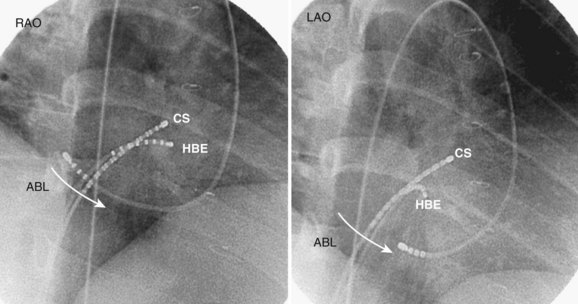
For CTI-dependent flutter, the ablation endpoint is demonstration of complete bi-directional conduction block within the isthmus. Different catheter configurations have been used, but a classic approach would include catheters positioned in the His-bundle, coronary-sinus, and tricuspid-annular locations (see Figure 27-7). Ablation may be performed during atrial flutter or sinus rhythm. Patients in sinus rhythm usually have ablation performed during pacing from the proximal coronary sinus to facilitate the identification of a change in activation sequence on the TA catheter signifying slowing of CTI conduction or block. The usual approach is anatomically guided and commences with ablation at the TA with either continuous pullback or focal point-by-point ablation across the CTI to the right atrium–inferior vena cava (RA–IVC) junction (eustachian ridge). At each point, the adequacy of the lesion is confirmed by the diminution of the local electrogram signal (Figure 27-5) and the emergence of local double potentials on the ablation catheter.
Even though the anatomic approach is the more widely used one, an alternative technique sequentially targets areas of high bipolar voltage along the CTI in descending order until block is achieved.29 In this small series, the authors demonstrated successful blockade in all patients, with recurrence at 8 months in 1 of 18 patients. The ability to produce complete blockade without a contiguous lesion set is in keeping with the anatomic description of the CTI being composed of discrete muscle bundles.
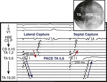
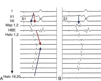
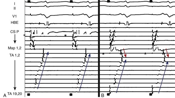
Endpoints for Ablation
Initial reports on the technique for ablation of the CTI focused on the termination of flutter during ablation and noninducibility.30 Since then, the importance of demonstrating complete bi-directional block across the CTI has been highlighted by greatly improved success rates of between 90% and 100%.1 Block from the septal aspect to the lateral aspect of the isthmus is readily appreciated by a sudden change in activation sequence on the TA catheter when pacing at the proximal CS (Figure 27-6). Activation after block is seen to descend down the lateral wall of the RA.30 Bi-directional block (i.e., lateral to septal) is confirmed by pacing from a site lateral to the CTI line. Activation should ascend along the lateral wall and descend at the septum, activating the atrium adjacent to the His-bundle catheter before the CS catheter (Figure 27-7).30 The mapping of locally split atrial double potentials (DPs) along the line of ablation can also assist in demonstrating complete block and distinguishing block from conduction slowing.31 If the spacing between DPs is less than 90 ms, a local gap should be suspected; mapping for areas with closely spaced DPs can assist when ablation has not yet produced complete block.32,33 A gap in the ablation line may also be identified by fractionated electrograms (Figure 27-8). Conversely, widely split local DPs more than 110 ms are associated with complete block.32,33 An increase in splitting of more than 50 ms from baseline is also indicative of block.34 If it is uncertain whether block is complete, based on local DPs, pacing from differential sites distant from the CTI on the septal and anterior walls can be helpful. When pacing further from the line of conduction block, the separation of local DPs decreases when block is complete.35,36 The trans-isthmus conduction interval, which can also be measured, is defined as the time between the pacing stimulus (either septal or lateral to the isthmus) and the local atrial electrogram on the contralateral side of the ablation line. An increase in the trans-isthmus conduction interval (interval between the pacing stimulus, either septal or lateral to the line of ablation, and the atrial electrogram on the other side of the CTI) of more than 50% from the baseline is highly predictive of complete isthmus block (see Figure 27-6).34 When evaluating the presence of complete block, it is important to pace and record immediately adjacent to either side of the line of block to avoid an “apparent” block (see example in Figure 27-9).
Occasionally, it may appear that block is incomplete due to pseudo-conduction. This occurs when conduction across the crista terminalis allows collision of wavefronts on the anterior right atrial wall mimicking trans-isthmus conduction. Pacing from the mapping catheter within the CTI immediately medial to the line of ablation and recording on the TA catheter immediately lateral can clarify this.35 Transient CTI block occurs and will usually demonstrate recovery of conduction within 20 to 30 minutes of ablation. Where practical, this should be the waiting period after block is seen to ensure the recovery does not occur.37
Radiofrequency remains the energy source of choice for ablation of typical atrial flutter. Studies have demonstrated that 8-mm tip catheters are superior to 4-mm tip catheters in terms of procedural duration and success.38 The use of irrigated tip catheters is also superior to standard 4-mm tip catheters.39 A recent comparison between irrigated 4-mm tip catheters and nonirrigated 8-mm tip catheters yielded equivalent results.40 The use of electroanatomic mapping produces results similar to those of conventional mapping in terms of procedure time and radiofrequency duration but reduces fluoroscopy time.41 Cryoablation has been used effectively and has the advantages of catheter stability and absence of pain.
As previously described, anatomic variations can cause difficulty achieving successful ablation.28 A prominent sub-eustachian pouch may result in inadequate power delivery when a nonirrigated catheter is used. Prominent pectinate muscles may pose difficulties with catheter stability and lesion depth creation. A more medial approach will help avoid the thicker musculature and the deep recesses between trabeculations. The use of linear phased-array intracardiac ultrasonography can assist in defining difficult anatomy.42
Procedural Efficacy
In a worldwide pooled analysis of ablation for CTI-dependent flutter, including more than 7000 patients, the long-term success was 97% with an incidence of major complications of 0.4%.43 Repeat procedures were, however, needed in 4%. The late occurrence of AF after ablation for CTI-dependent flutter is well recognized. It has been previously described that up to 70% of patients with a history of flutter ablation subsequently develop AF, even with no antecedent history of AF.44 More recently, another group demonstrated that 50% of patients with no history of AF subsequently develop this arrhythmia after successful ablation of flutter. The majority of these (almost 70%) developed AF within 1 year of the flutter ablation.45 The incidence of AF following ablation was similar when compared with that in a group of historical controls receiving pharmacologic management of flutter. In the majority of patients with atrial flutter, the arrhythmia commences via a transitional period of atrial fibrillation, which may be necessary for the development of a line of a functional block in the intercaval region of the right atrium.46 Despite the high late incidence of atrial fibrillation, ablation of CTI-dependent flutter provides good symptomatic relief with a reduced requirement for antiarrhythmic drugs and cardioversion for refractory arrhythmias and can facilitate management of AF.1,45,46
Lower Loop Re-entry
Lower loop re-entry is an uncommon variant of typical flutter manifesting as CCW activation around the IVC involving the CTI and the low posterior RA with conduction across the terminal crest. The turnaround point is thus lower than in typical flutter, and the cycle length is appropriately shorter.47 Despite these differences, ablation of the CTI is successful for treating this arrhythmia.
Atypical, or Non-CTI–Dependent Atrial Flutter
The term atypical atrial flutter encompasses a range of macro–re-entrant ATs that are not solely dependent on the CTI and whose surface ECG is not that of typical CCW or clockwise flutter. These atypical circuits can occur in the macroscopically normal heart or may be associated with previous cardiac surgery, congenital heart disease, and, as shown more recently, after ablation of atrial flutter. In patients with congenital heart disease, a thorough understanding of the underlying abnormality and the nature of corrective surgery, including surgical access, is essential. Macro–re-entry can exist in both left and right atria, and often multiple circuits can coexist. Dual-loop re-entry has been frequently described, and one circuit may involve the CTI. Indeed, even when the CTI is not involved in a circuit, it is important to also perform CTI ablation in this population, as otherwise there will be a high late incidence of CTI-dependent flutter. In one series, in which three-dimensional electroanatomic mapping was used, the CTI was involved in “incisional” flutter in 92%, with 27% being treated with CTI ablation alone. A line of DPs along the right atrial free wall was associated with dual loops in all instances.48 In patients with the substrate for macro–re-entry, “focal” sources with early activation and centrifugal spread may coexist.48,49
Nevertheless, three-dimensional mapping remains the cornerstone of ablation of these often complex circuits. High-density activation maps registered to critical anatomic structures provide a detailed understanding of the tachycardia sequence. Just as important is the anatomic information provided by voltage mapping that demonstrates regions of low voltage and scar, which are the potential anatomic obstacles and the substrate for re-entrant circuits. Lines of DPs and regions of fractionated electrograms can be annotated and may also be critical to the mechanism of tachycardia. Circuits may have a critical channel where focal ablation can terminate a macro–re-entrant circuit.50 Alternatively, some circuits are broad activation wavefronts without a critical channel. In these cases, ablation lines are created between scars or to anatomic obstacles such as the mitral or tricuspid annulus or the inferior or superior caval veins. In addition, these maps can be superimposed on detailed imaging by CT or MRI, thus allowing the correlation of the electrical substrate with anatomic structures.
Right Atrial Macro–Re-entry
Right atrial circuits independent of the CTI are an uncommon cause of right atrial macro–re-entry, accounting for 4% of cases, as reported by one series.51 The anatomic substrate for re-entry in this group appears to be spontaneous scarring in the free wall of the RA and is marked by the presence of DPs, areas of low voltage, and electrical silence.49,51 The high incidence of coexisting sinus node dysfunction highlights the global pathology of the right atrium in this population.49 The approach in this group invariably also involves ablation of the CTI, described previously as typical CCW flutter, which is nearly always also inducible. Ablation from the lower portion of the scar to the IVC is usually the narrowest part of the circuit, although the superior vena cava and the TA are alternative anatomic anchors.49,51 Channels within scars may also be seen, and ablation within these areas can also result in termination of the circuit.49 Ablation in this area may be painful, and potential phrenic nerve damage should be avoided by pacing at high output to exclude phrenic nerve capture before ablation.52 Acute success defined by termination and noninducibility is high in these patients, in excess of 90%.49,51
Upper Loop and Figure-of-8 Re-entry
Another type of atypical right atrial flutter involving the upper right atrial free wall has been termed upper loop re-entry.51,53 Noncontact mapping studies demonstrated this to comprise CCW (descending activation of free wall anterior to the CT) or clockwise (ascending activation of free wall anterior to the CT) activation involving the crista terminalis, an area of a functional block, and the superior vena cava.54 The lower turnaround point for these circuits is by conduction through a gap in functional block in the crista terminalis. Ablation in this conduction gap to complete the line of block is successful in treating this arrhythmia.54 This circuit may be seen in isolation as a single loop or be involved in dual-loop (figure-of-8) re-entry with lower-loop (type I figure-of-8 re-entry) or free-wall (type II figure-of-8 re-entry) circuits.55 In these cases, ablation of the free-wall channel (type II) and/or conduction gap in the crista terminalis (type I) is effective.55
“Incisional” Re-entry
Right atrial macro–re-entrant circuits resulting from previous atriotomy incisions for correction of congenital heart disease are well recognized and have been termed incisional or scar-mediated flutter.56
In patients with repair of atrial septal defect, atypical flutter most usually involves the atriotomy scar in the atrial free wall (Figure 27-10). Circuits involving the septal patch have rarely been reported. In patients with Mustard or Senning repair for dextro-transposition of the great arteries (D-TGA), the majority of circuits will involve the remnant of the CTI, which is now located in the pulmonary venous atrium.57 Access to this chamber is difficult and requires either a circuitous retrograde approach or puncture across a thick/prosthetic baffle; this is the limiting factor in ablation (Figure 27-11). Circuits in variants of Fontan repair are unique in that they infrequently involve the CTI in patients who often have tricuspid atresia. Circuits are most commonly found in the free wall and can involve the crista terminalis, the inferior or superior vena cavae, or the base of the conduit. Often these Fontan right atria are severely enlarged showing extensive regions of low voltage and scarring with multiple circuits. Patients with repair of tetralogy of Fallot may also develop atrial arrhythmias, as surgery frequently involves a trans-atrial approach resulting in a long free-wall scar.
Reported success rates for ablation of scar-mediated re-entry in patients with surgically corrected congenital heart disease have varied widely, particularly with the underlying condition, although acute success has been achieved in excess of 80%.48,56 Early recurrences may be as high as 59%, although long-term freedom from arrhythmias can be achieved in the majority of patients after multiple procedures.48
Left Atrial Macro–Re-entry
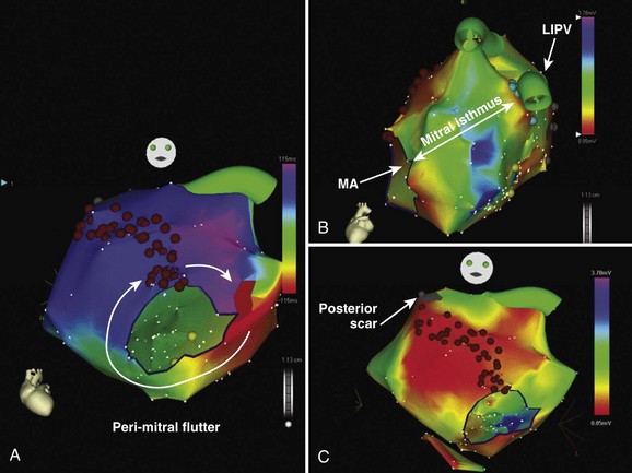
Left atrial flutter circuits typically involve re-entry around anatomic structures such as the mitral annulus, the pulmonary vein ostia, and regions of electrical silence or scar. The majority of these patients have significant structural heart disease such as cardiac failure, mitral valve disease, and left atrial enlargement.58 Areas of electrical silence demonstrated by voltage mapping most frequently occur in the posterior left atrium and the left atrial roof. Many of these circuits demonstrate broad activation wavefronts and dual-loop re-entry, and multiple circuits frequently occur. Perimitral re-entry, whether clockwise or CCW, is the most frequently observed circuit. Linear ablation is performed between the lateral mitral annulus and the left inferior pulmonary vein (through the “mitral isthmus”) with confirmation of a bi-directional conduction block using the CS catheter for recording conduction discontinuity and the mapping catheter for pacing (Figure 27-12). Ablation within the CS is often required to complete this line. Alternatively, ablation may be performed between two electrically silent anatomic obstacles (e.g., the mitral annulus and areas of left atrial scar) (see Figure 27-12). Circuits around the right-sided or left-sided veins can be successfully ablated with a “roof line” of ablation between the left and right superior pulmonary veins. For both the roof line and the mitral line, it may be necessary to perform circumferential ablation to isolate the pulmonary vein to “anchor” the roof or mitral line to a region of a conduction block. In some cases, scarring around the base of the pulmonary vein will obviate the need for circumferential isolation. Other circuits may be smaller and involve regions of scarring in the posterior atrium or in the roof.58 Circuits around silent areas can be ablated by joining these areas to one of the pulmonary veins or to another silent area.58 The acute success rates of approximately 70% for left atrial macro–re-entry are less than those of typical CTI-dependent flutter, with a significant proportion requiring multiple procedures.58 Left atrial macro–re-entry involving the CS musculature has also been reported and can be managed by circumferential ablation around the CS.59
Atrial Tachycardias After Catheter Ablation of Atrial Fibrillation
With the rapidly increasing number of patients undergoing ablation for atrial flutter, the incidence of AT as a byproduct of this procedure is also increasing. The reported incidence of AT after pulmonary vein isolation ranges from 4.7% to 25%, which reflects the wide variation in patient populations and in the initial ablation approaches.60–62 In general, initial conservative management with pharmacologic therapy and elective cardioversion is appropriate, as many of these circuits will settle spontaneously after the early postablation period.63 Of those with AT during the initial procedure, almost half experience spontaneous resolution.60 Of those with AT during short-term follow-up, approximately 30% experience spontaneous resolution.60 However, when the flutter persists beyond the first 3 months from the index ablation procedure for atrial flutter, it is probable that a further ablation procedure will be required.
In patients who have undergone only circumferential pulmonary vein isolation for paroxysmal AF without any additional substrate modification (linear or fractionated electrogram ablation), many tachycardias will be focal and related to pulmonary vein sources with reconnection of the pulmonary vein to the left atrium.64 Occasional non-PV foci will be involved. Simple pulmonary vein reisolation will be sufficient to cure the problem in the majority of cases. Macro–re-entrant circuits are not common in this population. The surface ECG PWM may be highly variable in these patients as previous ablation alters propagation patterns and hence the P-wave appearance.
In contrast, in patients who have undergone linear ablation for persistent AF, the most common mechanism of AT will be macro–re-entry related to gaps in previous ablation lines.60–62 The incidence of gap-related flutter will also depend on whether a bi-directional block across ablation lines was confirmed during the index procedure.63
In patients who have had extensive ablation of fractionated electrograms, small re-entrant circuits have been described.65 For some of these circuits, broad fractionated electrograms recorded on adjacent bipoles may cover the entire tachycardia cycle length.65–67
Recently, Jais et al described a deductive mapping strategy for atrial tachycardias following AF ablation based on three steps: (1) cycle length regularity, (2) search for macro–re-entry (entrainment involving >2 separate atrial segments), and (3) if macro–reentry excluded, search for focal origin giving a centrifugal activation of the atria.65 This strategy has proved to be highly effective. In addition, mapping of the RA and entrainment of the CTI should be performed prior to left atrial access, as previous ablation can alter the appearance of a typical CCW flutter.63
Reported success rates for ablation of AT following previous AF ablation have generally been high ranging from 77% to 93%.60–62 However, it should be recognized that when extensive atrial ablation is performed in patients with an abnormal atrial substrate, the potential for multiple different re-entrant circuits may develop.
Key References
Asirvatham SJ. Correlative anatomy and electrophysiology for the interventional electrophysiologist: Right atrial flutter. J Cardiovasc Electrophysiol. 2009;20:113-122.
Blomstrom-Lundqvist C, Scheinman MM, Aliot EM, et al. ACC/AHA/ESC guidelines for the management of patients with supraventricular arrhythmias—executive summary: A report of the American College of Cardiology/American Heart Association Task Force on Practice Guidelines and the European Society of Cardiology Committee for Practice Guidelines (Writing Committee to Develop Guidelines for the Management of Patients With Supraventricular Arrhythmias). Circulation. 2003;108:1871-1909.
Cosio FG, Awamleh P, Pastor A, Nunez A. Determining inferior vena cava-tricuspid isthmus block after typical atrial flutter ablation. Heart Rhythm. 2005;2:328-332.
Gerstenfeld EP, Marchlinski FE. Mapping and ablation of left atrial tachycardias occurring after atrial fibrillation ablation. Heart Rhythm. 2007;4:S65-S72.
Jais P, Matsuo S, Knecht S, et al. A deductive mapping strategy for atrial tachycardia following atrial fibrillation ablation: Importance of localized reentry. J Cardiovasc Electrophysiol. 2009;20(5):480-491. Epub Dec 22, 2008
Jais P, Shah DC, Haissaguerre M, et al. Mapping and ablation of left atrial flutters. Circulation. 2000;101:2928-2934.
Kalman JM, VanHare GF, Olgin JE, et al. Ablation of “incisional” reentrant atrial tachycardia complicating surgery for congenital heart disease. Use of entrainment to define a critical isthmus of conduction. Circulation. 1996;93:502-512.
Kistler PM, Roberts-Thomson KC, Haqqani HM, et al. P-wave morphology in focal atrial tachycardia: Development of an algorithm to predict the anatomic site of origin. J Am Coll Cardiol. 2006;48:1010-1017.
Knight BP, Ebinger M, Oral H, et al. Diagnostic value of tachycardia features and pacing maneuvers during paroxysmal supraventricular tachycardia. J Am Coll Cardiol. 2000;36:574-582.
Natale A, Newby KH, Pisano E, et al. Prospective randomized comparison of antiarrhythmic therapy versus first-line radiofrequency ablation in patients with atrial flutter. J Am Coll Cardiol. 2000;35:1898-1904.
Roberts-Thomson KC, Kistler PM, Kalman JM. Focal atrial tachycardia I: Clinical features, diagnosis, mechanisms, and anatomic location. Pacing Clin Electrophysiol. 2006;29:643-652.
Roberts-Thomson KC, Kistler PM, Kalman JM. Focal atrial tachycardia II: Management. Pacing Clin Electrophysiol. 2006;29:769-778.
Saoudi N, Cosio F, Waldo A, et al. Classification of atrial flutter and regular atrial tachycardia according to electrophysiologic mechanism and anatomic bases: A statement from a joint expert group from the Working Group of Arrhythmias of the European Society of Cardiology and the North American Society of Pacing and Electrophysiology. J Cardiovasc Electrophysiol. 2001;12:852-866.
Stevenson IH, Kistler PM, Spence SJ, et al. Scar-related right atrial macroreentrant tachycardia in patients without prior atrial surgery: electroanatomic characterization and ablation outcome. Heart Rhythm. 2005;2:594-601.
Tai CT, Liu TY, Lee PC, et al. Non-contact mapping to guide radiofrequency ablation of atypical right atrial flutter. J Am Coll Cardiol. 2004;44:1080-1086.
1 Blomstrom-Lundqvist C, Scheinman MM, Aliot EM, et al. ACC/AHA/ESC guidelines for the management of patients with supraventricular arrhythmias—executive summary: A report of the American College of Cardiology/American Heart Association Task Force on Practice Guidelines and the European Society of Cardiology Committee for Practice Guidelines (Writing Committee to Develop Guidelines for the Management of Patients With Supraventricular Arrhythmias). Circulation. 2003;108:1871-1909.
2 Saoudi N, Cosio F, Waldo A, et al. Classification of atrial flutter and regular atrial tachycardia according to electrophysiologic mechanism and anatomic bases: A statement from a joint expert group from the Working Group of Arrhythmias of the European Society of Cardiology and the North American Society of Pacing and Electrophysiology. J Cardiovasc Electrophysiol. 2001;12:852-866.
3 Chen SA, Tai CT, Chiang CE, et al. Focal atrial tachycardia: reanalysis of the clinical and electrophysiologic characteristics and prediction of successful radiofrequency ablation. J Cardiovasc Electrophysiol. 1998;9:355-365.
4 Kalman JM, Olgin JE, Karch MR, et al. “Cristal tachycardias”: Origin of right atrial tachycardias from the crista terminalis identified by intracardiac echocardiography. J Am Coll Cardiol. 1998;31:451-459.
5 Kistler PM, Fynn SP, Haqqani H, et al. Focal atrial tachycardia from the ostium of the coronary sinus: Electrocardiographic and electrophysiological characterization and radiofrequency ablation. J Am Coll Cardiol. 2005;45:1488-1493.
6 Roberts-Thomson KC, Kistler PM, et al. Focal atrial tachycardias arising from the right atrial appendage: Electrocardiographic and electrophysiologic characteristics and radiofrequency ablation. J Cardiovasc Electrophysiol. 2007;18:367-372.
7 Tada H, Nogami A, Naito S, et al. Simple electrocardiographic criteria for identifying the site of origin of focal right atrial tachycardia. Pacing Clin Electrophysiol. 1998;21:2431-2439.
8 Kistler PM, Sanders P, Hussin A, et al. Focal atrial tachycardia arising from the mitral annulus: electrocardiographic and electrophysiologic characterization. J Am Coll Cardiol. 2003;41:2212-2219.
9 Ouyang F, Ma J, Ho SY, et al. Focal atrial tachycardia originating from the non-coronary aortic sinus: Electrophysiological characteristics and catheter ablation. J Am Coll Cardiol. 2006;48:122-131.
10 Wang YL, Li XB, Quan X, et al. Focal atrial tachycardia originating from the left atrial appendage: Electrocardiographic and electrophysiologic characterization and long-term outcomes of radiofrequency ablation. J Cardiovasc Electrophysiol. 2007;18:459-464.
11 Yamada T, Murakami Y, Yoshida Y, et al. Electrophysiologic and electrocardiographic characteristics and radiofrequency catheter ablation of focal atrial tachycardia originating from the left atrial appendage. Heart Rhythm. 2007;4:1284-1291.
12 Kistler PM, Sanders P, Fynn SP, et al. Electrophysiological and electrocardiographic characteristics of focal atrial tachycardia originating from the pulmonary veins: Acute and long-term outcomes of radiofrequency ablation. Circulation. 2003;108:1968-1975.
13 Kistler PM, Roberts-Thomson KC, Haqqani HM, et al. P-wave morphology in focal atrial tachycardia: development of an algorithm to predict the anatomic site of origin. J Am Coll Cardiol. 2006;48:1010-1017.
14 Roberts-Thomson KC, Kistler PM, Kalman JM. Focal atrial tachycardia I: Clinical features, diagnosis, mechanisms, and anatomic location. Pacing Clin Electrophysiol. 2006;29:643-652.
15 Knight BP, Ebinger M, Oral H, et al. Diagnostic value of tachycardia features and pacing maneuvers during paroxysmal supraventricular tachycardia. J Am Coll Cardiol. 2000;36:574-582.
16 Roberts-Thomson KC, Kistler PM, Kalman JM. Focal atrial tachycardia II: Management. Pacing Clin Electrophysiol. 2006;29:769-778.
17 Tracy CM, Swartz JF, Fletcher RD, et al. Radiofrequency catheter ablation of ectopic atrial tachycardia using paced activation sequence mapping. J Am Coll Cardiol. 1993;21:910-917.
18 Tang K, Ma J, Zhang S, et al. Unipolar electrogram in identification of successful targets for radiofrequency catheter ablation of focal atrial tachycardia. Chin Med J (Engl). 2003;116:1455-1458.
19 Pappone C, Stabile G, De Simone A, et al. Role of catheter-induced mechanical trauma in localization of target sites of radiofrequency ablation in automatic atrial tachycardia. J Am Coll Cardiol. 1996;27:1090-1097.
20 Mohamed U, Skanes AC, Gula LJ, et al. A novel pacing maneuver to localize focal atrial tachycardia. J Cardiovasc Electrophysiol. 2007;18:1-6.
21 Wong T, Segal OR, Markides V, et al. Cryoablation of focal atrial tachycardia originating close to the atrioventricular node. J Cardiovasc Electrophysiol. 2004;15:838.
22 Granada J, Uribe W, Chyou PH, et al. Incidence and predictors of atrial flutter in the general population. J Am Coll Cardiol. 2000;36:2242-2246.
23 Medi C, Kalman JM. Prediction of the atrial flutter circuit location from the surface electrocardiogram. Europace. 2008;10:786-796.
24 Natale A, Newby KH, Pisano E, et al. Prospective randomized comparison of antiarrhythmic therapy versus first-line radiofrequency ablation in patients with atrial flutter. J Am Coll Cardiol. 2000;35:1898-1904.
25 Cabrera JA, Sanchez-Quintana D, Farre J, et al. The inferior right atrial isthmus: Further architectural insights for current and coming ablation technologies. J Cardiovasc Electrophysiol. 2005;16:402-408.
26 Waki K, Saito T, Becker AE. Right atrial flutter isthmus revisited: Normal anatomy favors nonuniform anisotropic conduction. J Cardiovasc Electrophysiol. 2000;11:90-94.
27 Becker R, Bauer A, Metz S, et al. Intercaval block in normal canine hearts: Role of the terminal crest. Circulation. 2001;103:2521-2526.
28 Asirvatham SJ. Correlative anatomy and electrophysiology for the interventional electrophysiologist: Right atrial flutter. J Cardiovasc Electrophysiol. 2009;20:113-122.
29 Redfearn DP, Skanes AC, Gula LJ, et al. Cavotricuspid isthmus conduction is dependent on underlying anatomic bundle architecture: Observations using a maximum voltage-guided ablation technique. J Cardiovasc Electrophysiol. 2006;17:832-838.
30 Poty H, Saoudi N, Nair M, et al. Radiofrequency catheter ablation of atrial flutter. Further insights into the various types of isthmus block: Application to ablation during sinus rhythm. Circulation. 1996;94:3204-3213.
31 Shah DC, Takahashi A, Jais P, et al. Local electrogram-based criteria of cavotricuspid isthmus block. J Cardiovasc Electrophysiol. 1999;10:662-669.
32 Tada H, Oral H, Sticherling C, et al. Double potentials along the ablation line as a guide to radiofrequency ablation of typical atrial flutter. J Am Coll Cardiol. 2001;38:750-755.
33 Morgan JM, Haywood G, Schirdewan A, et al. “Double” potentials define linear lesion conduction block using a novel mapping/linear lesion ablation catheter. J Cardiovasc Electrophysiol. 2003;14:236-242.
34 Oral H, Sticherling C, Tada H, et al. Role of transisthmus conduction intervals in predicting bidirectional block after ablation of typical atrial flutter. J Cardiovasc Electrophysiol. 2001;12:169-174.
35 Cosio FG, Awamleh P, Pastor A, Nunez A. Determining inferior vena cava-tricuspid isthmus block after typical atrial flutter ablation. Heart Rhythm. 2005;2:328-332.
36 Shah D, Haissaguerre M, Takahashi A, et al. Differential pacing for distinguishing block from persistent conduction through an ablation line. Circulation. 2000;102:1517-1522.
37 Bru P, Duplantier C, Bourrat M, et al. Resumption of right atrial isthmus conduction following atrial flutter radiofrequency ablation. Pacing Clin Electrophysiol. 2000;23:1908-1910.
38 Tsai CF, Tai CT, Yu WC, et al. Is 8-mm more effective than 4-mm tip electrode catheter for ablation of typical atrial flutter? Circulation. 1999;100:768-771.
39 Jais P, Shah DC, Haissaguerre M, et al. Prospective randomized comparison of irrigated-tip versus conventional-tip catheters for ablation of common flutter. Circulation. 2000;101:772-776.
40 Sacher F, O’Neill MD, Jais P, et al. Prospective randomized comparison of 8-mm gold-tip, externally irrigated-tip and 8-mm platinum-iridium tip catheters for cavotricuspid isthmus ablation. J Cardiovasc Electrophysiol. 2007;18:709-713.
41 Willems S, Weiss C, Ventura R, et al. Catheter ablation of atrial flutter guided by electroanatomic mapping (CARTO): A randomized comparison to the conventional approach. J Cardiovasc Electrophysiol. 2000;11:1223-1230.
42 Morton JB, Sanders P, Davidson NC, et al. Phased-array intracardiac echocardiography for defining cavotricuspid isthmus anatomy during radiofrequency ablation of typical atrial flutter. J Cardiovasc Electrophysiol. 2003;14:591-597.
43 Morady F. Catheter ablation of supraventricular arrhythmias: State of the art. J Cardiovasc Electrophysiol. 2004;15:124-139.
44 Hsieh MH, Tai CT, Chiang CE, et al. Recurrent atrial flutter and atrial fibrillation after catheter ablation of the cavotricuspid isthmus: A very long-term follow-up of 333 patients. J Interv Card Electrophysiol. 2002;7:225-231.
45 Luria DM, Hodge DO, Monahan KH, et al. Effect of radiofrequency ablation of atrial flutter on the natural history of subsequent atrial arrhythmias. J Cardiovasc Electrophysiol. 2008;19:1145-1150.
46 Waldo AL, Feld GK. Inter-relationships of atrial fibrillation and atrial flutter mechanisms and clinical implications. J Am Coll Cardiol. 2008;51:779-786.
47 Cheng J, Cabeen WRJr, Scheinman MM. Right atrial flutter due to lower loop reentry: Mechanism and anatomic substrates. Circulation. 1999;99:1700-1705.
48 Magnin-Poull I, De Chillou C, Miljoen H, et al. Mechanisms of right atrial tachycardia occurring late after surgical closure of atrial septal defects. J Cardiovasc Electrophysiol. 2005;16:681-687.
49 Stevenson IH, Kistler PM, Spence SJ, et al. Scar-related right atrial macroreentrant tachycardia in patients without prior atrial surgery: Electroanatomic characterization and ablation outcome. Heart Rhythm. 2005;2:594-601.
50 Nakagawa H, Shah N, Matsudaira K, et al. Characterization of reentrant circuit in macroreentrant right atrial tachycardia after surgical repair of congenital heart disease: Isolated channels between scars allow “focal” ablation. Circulation. 2001;103:699-709.
51 Kall JG, Rubenstein DS, Kopp DE, et al. Atypical atrial flutter originating in the right atrial free wall. Circulation. 2000;101:270-279.
52 Cosio FG, Martin-Penato A, Pastor A, et al. Atypical flutter: A review. Pacing Clin Electrophysiol. 2003;26:2157-2169.
53 Yang Y, Cheng J, Bochoeyer A, et al. Atypical right atrial flutter patterns. Circulation. 2001;103:3092-3098.
54 Tai CT, Huang JL, Lin YK, et al. Noncontact three-dimensional mapping and ablation of upper loop re-entry originating in the right atrium. J Am Coll Cardiol. 2002;40:746-753.
55 Tai CT, Liu TY, Lee PC, et al. Non-contact mapping to guide radiofrequency ablation of atypical right atrial flutter. J Am Coll Cardiol. 2004;44:1080-1086.
56 Kalman JM, VanHare GF, Olgin JE, et al. Ablation of “incisional” reentrant atrial tachycardia complicating surgery for congenital heart disease. Use of entrainment to define a critical isthmus of conduction. Circulation. 1996;93:502-512.
57 Kanter RJ, Papagiannis J, Carboni MP, et al. Radiofrequency catheter ablation of supraventricular tachycardia substrates after Mustard and Senning operations for d-transposition of the great arteries. J Am Coll Cardiol. 2000;35:428-441.
58 Jais P, Shah DC, Haissaguerre M, et al. Mapping and ablation of left atrial flutters. Circulation. 2000;101:2928-2934.
59 Olgin JE, Jayachandran JV, Engesstein E, et al. Atrial macroreentry involving the myocardium of the coronary sinus: A unique mechanism for atypical flutter. J Cardiovasc Electrophysiol. 1998;9:1094-1099.
60 Chugh A, Oral H, Lemola K, et al. Prevalence, mechanisms, and clinical significance of macroreentrant atrial tachycardia during and following left atrial ablation for atrial fibrillation. Heart Rhythm. 2005;2:464-471.
61 Mesas CE, Pappone C, Lang CC, et al. Left atrial tachycardia after circumferential pulmonary vein ablation for atrial fibrillation: Electroanatomic characterization and treatment. J Am Coll Cardiol. 2004;44:1071-1079.
62 Chae S, Oral H, Good E, et al. Atrial tachycardia after circumferential pulmonary vein ablation of atrial fibrillation: Mechanistic insights, results of catheter ablation, and risk factors for recurrence. J Am Coll Cardiol. 2007;50:1781-1787.
63 Gerstenfeld EP, Marchlinski FE. Mapping and ablation of left atrial tachycardias occurring after atrial fibrillation ablation. Heart Rhythm. 2007;4:S65-S72.
64 Gerstenfeld EP, Callans DJ, Dixit S, et al. Mechanisms of organized left atrial tachycardias occurring after pulmonary vein isolation. Circulation. 2004;110:1351-1357.
65 Jais P, Matsuo S, Knecht S, et al. A deductive mapping strategy for atrial tachycardia following atrial fibrillation ablation: Importance of localized reentry. J Cardiovasc Electrophysiol. 2009;20(5):480-491. Epub Dec 22, 2008
66 Haissaguerre M, Hocini M, Sanders P, et al. Localized sources maintaining atrial fibrillation organized by prior ablation. Circulation. 2006;113:616-625.
67 Jais P, Sanders P, Hsu LF, et al. Flutter localized to the anterior left atrium after catheter ablation of atrial fibrillation. J Cardiovasc Electrophysiol. 2006;17:279-285.