Chapter 28 Electrophysiological Evaluation of Atrial Fibrillation
Introduction
Atrial fibrillation (AF), one of the earliest arrhythmias described, is the most common cardiac arrhythmia in humans and is particularly common in older adults. The Framingham Heart Study noted that the incidence of AF in individuals age 60 years was 4% and as high as 15% in those older than 70 years.1 Effective evaluation and management of AF will have substantial clinical and public health impact in an aging population. The mechanisms of AF have been widely debated and are often extrapolated from experimental data. These are discussed in Chapter 4. Human studies have reported data regarding clinical mechanisms that are at significant variance with some experimental concepts. Clinical investigations have centered on the relative role of triggers and substrate, focal automaticity and organized versus random re-entry, and the applicability of experimental and mathematical models to human AF. The clinical electrophysiological study (EPS) remains the gold standard for the investigation and evaluation of human AF.
The major objectives in a clinical EPS of a patient with AF are presented in Box 28-1.
Box 28-1 Goals for Electrophysiological Evaluation of Atrial Fibrillation
Electrocardiographic Definition and Clinical Classification
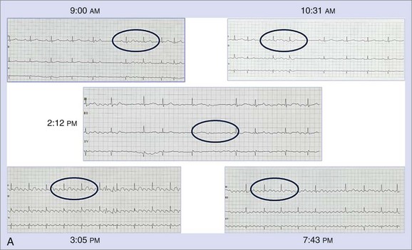
AF is characterized by the absence of P waves and the presence of small, irregular oscillations (fibrillatory, or f, waves) on electrocardiographic recordings. Fibrillation has been defined as either fine or coarse, based on the ability to discern well-defined f waves, without evidence of organized activity in the surface electrocardiogram (ECG). More recently, organized tachycardias have been documented at the onset of AF events, in intracardiac recordings at surgery, or during clinical EPSs performed in patients with AF.2–4 Recent reports that used advanced mapping techniques have documented multiple organized atrial tachyarrhythmias in a given patient with AF.5 Careful evaluation of ECGs with high gain or body surface mapping reveals evidence of varying f-wave morphology and periods of atrial flutter or atrial tachycardia (AT). (Figure 28-1, A).6,7
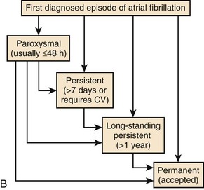
The current clinical classification of AF defines new-onset AF (first episode) or recurrent AF (≥2 episodes) with three types of presentation.8,9 Paroxysmal AF is defined as recurrent AF that terminates spontaneously within 7 days, whereas persistent AF is AF that is sustained beyond 7 days, or lasts fewer than 7 days but requires pharmacologic or electrical cardioversion (see Figure 28-1, B). The difference between the two clinical AF presentations may lie in the probability of AF termination within a defined period, which, in turn, may be based on the complexity of the AF mechanisms initiating or maintaining AF. When cardioversion fails or is not attempted, the patient has been defined as having permanent AF. More recently, aggressive cardioversion with high-energy, repeated shocks or intracardiac shocks has demonstrated effective termination of even permanent AF, leading to decreasing use of this term. Thus, it is more appropriate to define persistent AF as being new-onset or established (duration ≥1 year) persistent AF. A particular patient may have AF episodes that fall into one or more of these categories. The relationship of clinical classes of AF to EPS findings in each class is examined later.
Intracardiac Electrophysiological Studies for the Evaluation of Atrial Fibrillation
Early Electrophysiological Observations in Atrial Fibrillation
Early EPSs in patients with AF used limited recording and stimulation methods. The focus of the studies was largely on measurement of atrial electrophysiological properties, assessment of atrial conduction in the right atrium (RA) and the left atrium (LA), and the atrioventricular (AV) propagation of paced atrial beats or spontaneous or induced AF or other concomitant tachyarrhythmias. Two or three multi-polar catheters were typically positioned in the high RA and the mid-RA, His bundle region, and the coronary sinus.10 Abbreviation of atrial effective and functional refractory periods during programmed atrial stimulation is seen in patients with AF, with concomitant loss of rate adaptation atrial refractoriness. In addition, an increase in the dispersion of atrial refractoriness in the atria occurs in these patients compared with control subjects.11 Intra-atrial conduction times in humans show increased conduction delay in the RA, manifest as increased P-A intervals, and prolonged inter-atrial conduction time measured as P–distal coronary sinus interval. These delays account for the prolonged global P-wave duration seen on the ECG (Figure 28-2). More recently, other markers of conduction delay during sinus rhythm have been identified, including fragmented or multi-phasic intracardiac atrial potentials and late potentials on P-wave signal-averaged ECG recordings. Regional intracardiac atrial electrogram recordings show a propensity for split potentials in certain locations (e.g., crista terminalis, coronary sinus, eustachian ridge at the cavo-tricuspid isthmus, posterior LA), suggesting that anatomic structure can alter atrial electrical propagation patterns. Attuel emphasized the importance of increased dispersion of atrial refractoriness in these patients and its relationship to inducible AF.11,12
Programmed Stimulation for Induction of Atrial Fibrillation
Programmed atrial stimulation was first introduced in patients with AF by Haft more than 30 years ago.13 Single-paced atrial premature beats during atrial pacing or sinus rhythm–induced episodes of AF or flutter in these patients. This was accepted as a marker of atrial vulnerability to AF. Subsequently, Bauernfeind et al studied patients with Wolff-Parkinson-White (WPW) syndrome and AF and performed tests to select an effective drug therapy.14 Effectiveness in these studies was defined by prolongation of atrial refractoriness, abolition of accessory pathway conduction, and suppression of inducible AF. A standardized protocol for programmed stimulation in AF was first proposed by our group in 1999 and is described in detail later in the chapter.15
Atrial Fibrillation Mapping and Anatomic-Physiological Correlations
More recently, the focus of electrophysiological evaluation has shifted to mapping of either induced or spontaneous AF, detailed activation mapping of the RA and LA for triggers, organized tachycardias, identification of an abnormal atrial substrate, or all of these findings. All of these are demonstrable with atrial tissue voltage mapping or atrial electrogram morphologic abnormalities in sinus rhythm or AF (Figure 28-3). Such mapping is accomplished by placement of multiple electrode catheters in the RA and LA and is complemented by three-dimensional contact mapping or noncontact mapping (NCM) of the atrium. In this chapter, the multi-electrode catheter approach is discussed first. Three-dimensional mapping techniques are discussed in detail elsewhere. We have combined these two methods in a single procedure designed to achieve a complete electrophysiological evaluation, with simultaneous bi-atrial mapping complemented by high-resolution NCM mapping of the atrium of interest. This approach permits beat-to-beat real-time activation mapping of AF from onset to termination.
Clinical Electrophysiological Techniques for the Evaluation of Atrial Fibrillation
Contact Electrode Catheter Techniques
Clinical EPS in a patient with AF should consist of a systematic approach to the analysis of arrhythmias by recording and measuring a variety of electrophysiological parameters and events with the patient in sinus rhythm, AF, or both and by evaluating his or her response to programmed electrical stimulation. The study includes the measurement of conduction intervals (if necessary after cardioversion), the use of programmed atrial stimulation, and responses to a variety of interventions. Electrograms are recorded at paper speeds of 100 to 200 mm/s. At a minimum, multi-electrode catheters are placed in the high lateral RA, across the bundle of His, and in the coronary sinus to record left atrial electrograms and activation. Right atrial recordings can be obtained from the free wall, the septum, and the tricuspid isthmus for regional right atrial activation patterns (Figure 28-4). A duo-decapolar catheter is widely used for this purpose. This catheter is typically placed with its distal electrode in the low lateral right atrial free wall with the proximal set lying along the inter-atrial septum (see Figure 28-4, C). This allows simultaneous recordings of the anterior free wall of the RA and the inter-atrial septum.
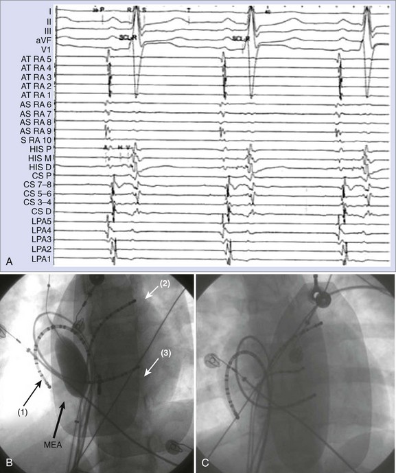
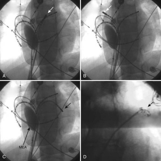
Left atrial recordings can be indirectly obtained epicardially from the left pulmonary artery or directly endocardially after a trans-septal puncture. In the former, a decapolar catheter is placed in the left lower pulmonary artery in a branch typically encircling the left atrial appendage (LAA) (see Figure 28-4, C). In this fashion, recordings from the left atrial lateral wall, left superior pulmonary vein (PV), roof of the LA and PVs, and right superior PV can be indirectly obtained to evaluate conduction in the superior LA. Trans-septal left atrial mapping requires inter-atrial septal puncture at the fossa ovalis by using a Brockenborough needle mounted within a trans-septal sheath and dilator assembly, usually guided by intracardiac echocardiography. Although detailed technical steps in this procedure are beyond the scope of this chapter, the important elements are illustrated in Videos 28-1 through 28-6 on the Expert Consult web site that accompanies this textbook. With the trans-septal approach, the distal electrode can be placed in the left superior PV, across the left atrial roof and the fossa ovalis. The catheter can also be manipulated into each of the PVs for mapping (Figure 28-5; see Videos 28-7 to 28-10). Note the proximity of the left pulmonary artery electrode catheter to the trans-septal electrode catheter along the superior LA (see Figure 28-5, B).
The ablation catheter is repositioned in the left inferior pulmonary vein region for mapping.
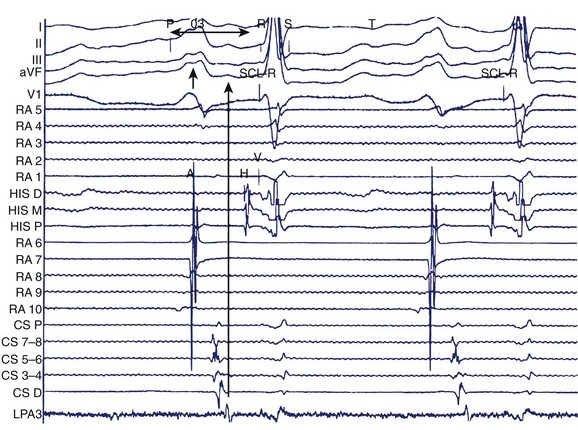
Alternatively, preformed electrode catheters can be used to map the atrium or PVs. A circular preformed multi-electrode catheter (e.g., Lasso catheter, Biosense Webster, Diamond Bar, CA) or small linear catheters (e.g., Cardima Pathfinder, Cardima Inc., Fremont, CA) can also be used for mapping within tubular structures—such as the PVs, the superior vena cava (SVC) or the inferior vena cava (IVC), the coronary sinus, or atrial appendages—or at their ostia in the atrium. The Lasso catheter comes in different configurations (10 or 20 electrode poles) and variable spacing (8 mm, 2-6-2 mm) and curve diameters (see Figure 28-5, D). It allows circular mapping at the PV ostia, which can have varying anatomic configurations, and within the veins for segmental mapping. The Pathfinder catheter permits placement well inside the vein and its branches. Because ablation within the PV is being undertaken with decreasing frequency, this is most useful in careful assessment of gaps in isolation lines. Activation within the veins during sinus rhythm, paced atrial stimuli, and spontaneous premature atrial beats can be recorded and localized. Figure 28-6 shows recordings during atrial pacing in a patient with persistent AF. The ablation catheter records a delayed potential within the left superior PV, and a spontaneous atrial premature beat originates from this site with electrogram sequence reversal confirming the PV potential (PVP) as the second component of the local electrogram.
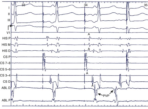
FIGURE 28-6 Pulmonary vein potential shown by arrow during atrial pacing as a second deflection after atrial electrogram and as trigger of atrial premature beat preceding the surface P wave and atrial electrograms in the coronary sinus and bundle of His regions. See legend to Figure 28-1 for abbreviations.
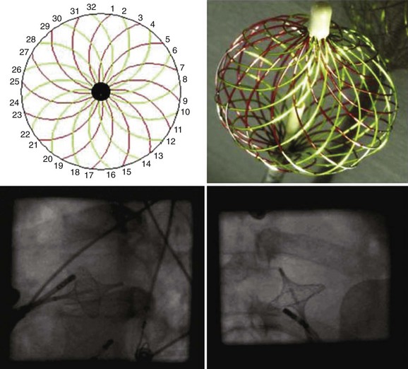
A multi-electrode basket catheter has been designed for global right atrial and left atrial mapping.16 Recently, the use of the High Density Mesh Mapper–Ablator catheter (Bard Electrophysiology, Lowell, MA) was described.17 It allows multiple simultaneous recordings along vertical splines in a circumferential array when the basket or mesh catheter is opened to achieve contact with the endocardium in the atrium of interest (Figure 28-7). A computer contour of atrial activation is developed on the basis of electrogram timing. Severe atrial dilation or anatomic abnormalities may impede complete recording sequences. One prospective study of PV isolation in patients with AF who have this device demonstrated that the method was safe and yielded good primary success rates and a favorable clinical outcome at 6 months.17 A more recent report showed a substantially higher AF recurrence rate at 18 months.18
Pacing Techniques During Electrophysiological Evaluation
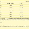
One standard programmed stimulation protocol based on prior studies conducted by our group is to use one to three atrial extrastimuli using two drive trains.15 At a minimum, two stimulation sites, that is, the high RA and the coronary sinus ostium, are used. Additional stimulation sites can include the distal coronary sinus, the LA, or PVs. The definition used for inducible sustained AF is a tachyarrhythmia longer than 30 seconds. The sensitivity for induction of AF with this protocol was 89% and the specificity was 92% (Figure 28-8).
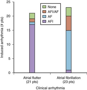
Figure 28-9, A, shows a typical programmed electrical stimulation protocol in a patient with AF. Note the induction of right atrial flutter with a clockwise activation pattern and a cycle length of 240 ms. Induction of organized tachyarrhythmias in patients with AF should alert the operator to the existence of such tachycardias in the initiation or maintenance of AF in that patient. Often, more than one such tachyarrhythmia will be elicited, especially in patients with persistent AF. Spontaneous AF episodes can also be recorded and the evolution of AF examined (see Figure 28-9, B). Note the conversion of an organized tachyarrhythmia seen as coarse AF on the ECG in this patient to a more complex arrhythmia with the evolution of fine AF and the appearance of fragmented electrical activity, initially in the coronary sinus electrograms and later in the septal electrograms. This continuous fractionated electrical activity is often referred to as complex fractionated atrial electrogram (CFAE) mapping and is used as a target for substrate ablation. In addition, pacing can be performed in specific atrial regions to assess conduction across anatomic obstacles (e.g., the cavo-tricuspid isthmus). Rapid atrial pacing can be used for entrainment and termination of organized tachycardias (discussed in more detail elsewhere in this text). Burst pacing is often unsuccessful in the termination of rapid tachycardias (see Figure 28-9, C). Giorgberidze et al reported modest success with high-frequency atrial pacing during organized tachycardias seen in patients with AF.19 Pacing within and immediately outside PVs can be performed for entrance and exit block before and after an intervention (see Figure 28-9, D).
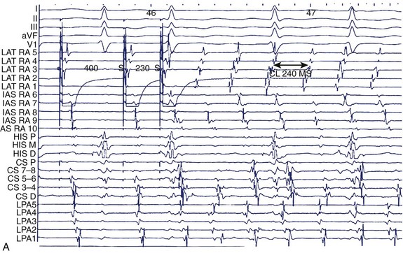
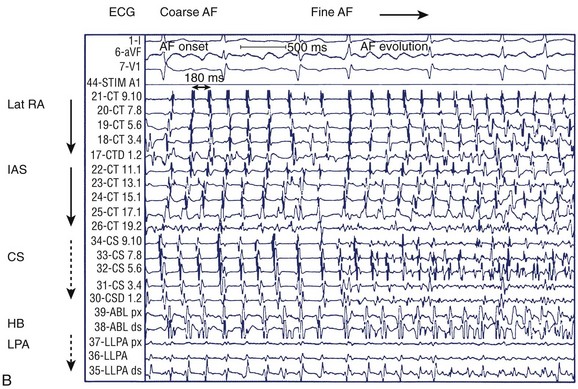
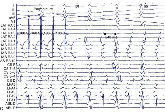
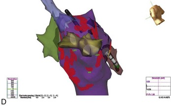
FIGURE 28-9 A, Induction of typical atrial flutter at electrophysiological study with single atrial extrastimulus in a patient with atrial fibrillation (AF). B, Transition from onset of coarse AF with an isoelectric period to fine sustained AF on the electrocardiogram. Note the organized atrial tachyarrhythmia on the left and the subsequent appearance of fibrillatory activity in the intracardiac recordings. C, Failure of rapid atrial pacing during AF despite evidence of resetting and possible entrainment of right atrial tachyarrhythmia but failure to interrupt AF because of inability to terminate right atrial tachyarrhythmia and pacing had no effect on left atrial tachyarrhythmia. D, Three-dimensional map of the left atrium using the Nav-X system (left posterolateral view; St. Jude Medical) with electrode catheter placement in the right inferior pulmonary vein after pulmonary vein antral isolation. Note that the pulmonary vein antra are encircled with ablation lesions. The catheter is advanced into the right inferior pulmonary vein with gradual disappearance of electrogram recordings seen on the display from the distal electrode, demonstrating complete vein isolation (arrow). See Figure 28-1 for abbreviations.
(B, From Saksena S, Skadsberg ND, Rao HB, Filipecki A: Biatrial and three-dimensional mapping of spontaneous atrial arrhythmias in patients with refractory atrial fibrillation, J Cardiovasc Electrophysiol 16[5]:494–504, 2005.)
Interventions During Electrophysiological Studies in Atrial Fibrillation
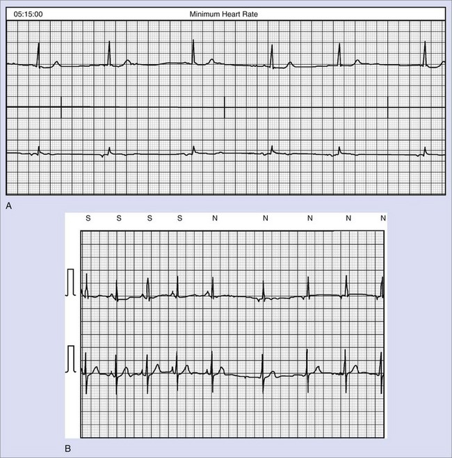
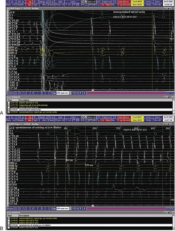
A variety of interventions can be used during electrophysiological studies in patients with AF. Most commonly, these are used to initiate spontaneous AF or to terminate an arrhythmia event. Spontaneous AF events may fail to occur during EPS. Isoproterenol is commonly used to elicit such events by increasing trigger activity, particularly from PVs. Isoproterenol has been used at moderate to high doses (4 to 15 µg/min) to initiate spontaneous AF. Consideration of concomitant comorbid conditions such as ischemia or heart failure should guide its use. Hemodynamic monitoring is desirable in this instance. Rare instances of adenosine or vagomimetic drugs to induce AF have been reported. Adenosine, methacholine, and even alcohol infusions have been used to elicit AF in the laboratory. Alternatively, the authors have found that cardioversion of sustained AF can allow emergence of spontaneous atrial premature beats (APBs) and AF events after cardioversion. Figure 28-10 shows early recurrence of triggering APBs with short salvoes of AT, followed by spontaneous onset of an AF episode. The onset tachycardia is a type 1 counterclockwise atrial flutter, which rapidly induces a left atrial tachyarrhythmia from the superior LA, probably arising in PVs. Early recurrences of AF have, in our experience, been similar to spontaneous AF events in origin and propagation.
Choice of Mapping Techniques
Until now, catheter mapping of human AF has been limited to electrogram recordings in specific regions of interest (e.g., PVs), and regional mapping has been limited to intraoperative studies.20 Several techniques have been reported for the regional catheter mapping of discrete focal sources of AF in specific atrial regions.21 For example, a Lasso catheter can be used for the focal mapping of PVs, where rapidly firing foci play an important role in the initiation and maintenance of AF.3 However, a major limitation of the regional catheter method has been infrequent and sporadic recordings of spontaneous AF, necessitating repetitious stable rhythms.
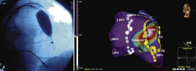
In an effort to overcome such limitations, several elegant, high-resolution catheter mapping systems have been developed, allowing three-dimensional anatomic assessment coupled with electrophysiological recordings to create an accurate picture of the heart’s electrical sequence (Figures 28-11 and 28-12). The CARTO mapping system (Biosense Webster) uses ultra-low magnetic field technology to reconstruct three-dimensional maps and activation sequences. The Nav-X system (St. Jude Medical, St Paul, MN) uses similar principles to create static anatomic maps. The EnSite system (St Jude Medical) uses a multi-electrode mapping balloon catheter to create maps and define the location of the mapping and ablation catheter. The detailed function of these systems is discussed in Chapter 92. All these systems represent a paradigm shift in the way that AF can be mapped and AF ablations are performed. Recent tools allow integration of real-time catheter-based mapping with imported scans from magnetic resonance imaging (MRI) or computed tomography (CT).22 Coupled with the identification of CFAEs, such mapping systems facilitate ablation procedures in patients with persistent or permanent AF.
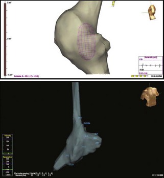
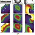
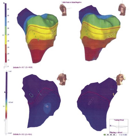
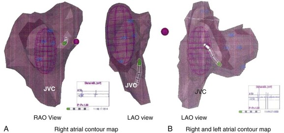
FIGURE 28-11 Right atrial contour maps developed using the magnetic navigation method with the Nav-X system (lower panel; St. Jude Medical) and the virtual contour using the noncontact mapping approach with EnSite balloon array (top panel; St. Jude Medical). Note the similarity of anatomic structural details with display of electrograms from the catheter electrode tip with both systems. In addition, the balloon array permits global atrial activation recordings on a beat-to-beat basis (see Figure 28-13).
Bi-atrial Contact and Noncontact Mapping Techniques
Recently, our group has integrated simultaneous bi-atrial catheter mapping with high-resolution, three-dimensional noncontact mapping to provide a rapid and reliable method to map both induced and spontaneous AF.5,23,24 The major advance with this technique is to permit beat-to-beat simultaneous bi-atrial mapping that greatly shortens the mapping procedure. Triggers and tachycardias can be mapped in single cardiac cycles. In brief, four to six multi-polar electrode catheters are placed in the RA at the lateral RA, the bundle of His, the inter-atrial septum, the coronary sinus, the LA (via a patent foramen ovale), or the left pulmonary artery (under local anesthesia). When ablation is planned, a trans-septal puncture may be substituted for indirect recordings from a pulmonary artery. An endocardial balloon electrode (EnSite) can be introduced into the atrium of interest (see Figures 28-4 and 28-5, C). On occasion, the balloon can be placed in the LA and later relocated to the RA for bi-atrial high-resolution mapping (see Figure 28-10). Three-dimensional mapping of AF in the RA or LA is then combined with the contact catheter map.
A three-dimensional contour in the RA or LA can be developed with the array and is comparable with the chamber contours seen with electroanatomic systems (see Figure 28-11). On occasion, the two contours can be integrated (see Figure 28-12). The electrode catheter recordings and locations can be anatomically located on the contour. We use identifiable landmarks in the lateral RA, such as the orifices of the great veins, the entire ring of the tricuspid annulus, the coronary sinus ostium, the tricuspid valve–IVC isthmus sites, the lateral RA from superior to inferior locations, and the inter-atrial septum at multiple sites along a cranio-caudal axis.
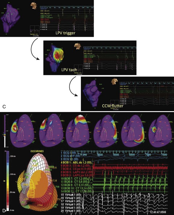
Beat-to-beat mapping is feasible. Figure 28-13, A, shows a static image with combined contact electrode locations on the three-dimensional contour. Figure 28-13, B, shows simultaneous display of contact electrograms and virtual recordings from the balloon array. The activation wavefront can be seen in multiple frames in a single cycle; also, the isochrones map of this cycle is seen in the lower left corner. This can also be viewed online as a continuous loop (see Videos 28-11 and 28-12). This integrated display is now ready for the acquisition and analysis of different rhythms. Sinus rhythm propagation, extrastimulus behavior, and induced or spontaneous arrhythmia initiation can be studied with these recordings. Beat-to-beat imaging and analysis are feasible in real time. During sustained tachyarrhythmias, whether induced or spontaneous, arrhythmia circuits can be correlated with their anatomic locations. For example, Video 28-11 shows a noncontact map of the RA at the onset of a spontaneous AF event, starting as an organized type 1 counterclockwise right atrial flutter that is succeeded by a left atrial tachyarrhythmia with bystander right atrial activation on the noncontact map. AF or other associated tachyarrhythmias may occur spontaneously during the study. Alternatively, they may have to be induced for analysis. Induced AF may differ in some features from spontaneous AF or may evolve into patterns similar to spontaneous AF.
(D Modified from Saksena S, Skadsberg ND, Rao HB, Filipecki A: Biatrial and three-dimensional mapping of spontaneous atrial arrhythmias in patients with refractory atrial fibrillation, J Cardiovasc Electrophysiol 16[5]:494–504, 2005.)
Clinical Electrophysiological Findings in Atrial Fibrillation
Normal Atrial Electrophysiology
Intra-atrial conduction in the RA is determined from the P-A interval, is commonly found between the middle and distal coronary sinus leads, and should not exceed 130 ms. The routes of inter-atrial conduction are complex and have been studied by using detailed atrial mapping with noncontact and contact approaches. Rossi noted that the atrial septum was contributed to by both RA and LA fiber bundles, which wrapped along the coronary sinus.25 Physiological studies have suggested that inter-atrial conduction occurs over Bachmann’s bundle in the inter-atrial groove. It was also noted that ostial coronary sinus stimulation propagated along the mitral valve ring first before the rest of the LA was activated, suggesting an inferior inter-atrial connection.26 Lemery and colleagues performed right atrial and left atrial noncontact mapping during sinus rhythm and atrial pacing and demonstrated inter-atrial conduction over two distinct regions via Bachmann’s bundle and the coronary sinus.27 Regional atrial conduction shows splitting of wavefronts along the crista terminalis anteriorly and posteriorly and preferential propagation along the superior and inferior LA. Left atrial activation may be indirectly recorded as a far-field signal in the PV.
Atrial Electrophysiology in Disease States
Observed abnormalities of diseased human atria in experimental studies include elevation of the resting membrane potential, depression of the maximal amplitude of the potential, and decreased upstroke velocity of the action potential. Such abnormalities have been related to a patient’s history of atrial tachyarrhythmia and the presence of a dilated atrium.28,29 In patients with sick sinus syndrome and lone AF or a history of primary atrial tachyarrhythmia, inter-atrial and intra-atrial conduction times were found to be increased.30,31 Furthermore, induction of atrial tachyarrhythmias by atrial extrastimulation was highly correlated with increases in the inter-atrial or intra-atrial conduction times. Three-dimensional noncontact mapping can show slowly propagating atrial activation in the diseased atrial substrate, with low-voltage electrograms, fragmentation and split potentials, and areas of conduction block (see Figure 28-3). These can be more obvious during spontaneous or induced AF. Bi-atrial reductions in electrogram voltage during three-dimensional mapping of patients with lone AF have been documented.32 Regional variability in alterations in conduction velocity and regional changes in atrial refractoriness were noted. In 20 patients undergoing bi-atrial high-density contact mapping, spectral analysis demonstrated greater fractionation and higher dominant frequencies in patients with persistent AF and in the LA during AF compared with patients with paroxysmal AF.33
Regional Atrial Electrophysiology
Animal models and studies in humans have demonstrated the important role atrial fibrosis plays in the development and maintenance of AF.34,35 Marcus et al reported significant regional variability in left atrial voltage as assessed by electroanatomic mapping in patients with atrial arrhythmias and in patients with AF who exhibited significantly more low-voltage areas in the septum and posterior walls.36 Although voltage is only a potential surrogate for fibrosis, these findings align with a histologic study in patients with AF and mitral valve disease in whom a disproportionate amount of fibrosis was located in the septum and posterior wall of the LA.37 Additionally, the investigators found that left atrial electrogram amplitude decreased with age. Aging was found to be associated with regional conduction slowing, anatomically determined conduction delay at the crista, and structural changes that include areas of low voltage in the RA.38 This electrical and structural remodeling may explain the increased propensity to AF with aging. In patients with symptomatic congestive heart failure (CHF), electroanatomic maps demonstrated lower mean voltage and greater heterogeneity in voltage compared with those in 21 controls undergoing radiofrequency (RF) ablation for AV nodal re-entrant tachycardia.39 Electroanatomic and conventional mapping techniques provided evidence of significantly impaired atrial conduction throughout the RA as well as anatomically determined functional conduction delay at the crista and indirect evidence of conduction slowing across the LA and Bachmann’s bundle. Fractionated electrograms in the atrial substrate are now being targeted for ablation, particularly in patients with persistent AF.35 Figure 28-9, B, shows the appearance of fractionation in coronary sinus electrograms, low septal electrograms, ablation electrograms, and posterosuperior left atrial recordings. The mechanism of these electrograms remains under investigation.
Pulmonary Vein Electrophysiology
PVs play an important role both in the onset and in the maintenance of AF. Early observations by Haïssaguerre et al demonstrated that AF initiation is often caused by focal electrical discharges predominantly located within PVs.3 PV electrograms can be mapped as described earlier. All four veins are mapped, and electrical activity resulting in premature beats or an atrial tachycardia can occur spontaneously or be induced by electrical stimulation or pharmacologic agents or even cardioversion shocks. In patients with AF, pulmonary venous effective refractory periods (ERPs) were significantly shorter than left atrial ERPs and significantly shorter than the PV ERPs of patients without AF.40 The PV potential functional refractory periods (FRPs) of patients with AF were also significantly shorter than those of controls, whereas the FRPs of the PV-LA junction and the left atrial ERPs were comparable, demonstrating that the main difference between patients with AF and those without AF is observed in PVs rather than at the junction with the LA or in the LA itself. In association with the more pronounced decremental conduction times in PVs, these short ERPs and FRPs provide a very favorable milieu for arrhythmogenicity, particularly re-entry in or around the veins, which may perpetuate arrhythmia and thus act as a substrate for AF maintenance.
Similar electrophysiological properties of PVs and atria have been reported when exposed to short-term AF induced by rapid atrial burst pacing, which suggests electrical remodeling as a potential mechanism.41 However, as the disease progresses from paroxysmal AF to permanent, long-term AF, other processes occur in the atria leading to contractile and structural remodeling.42
Insights into Atrial Fibrillation Mechanisms from Bi-atrial and Three-Dimensional Mapping
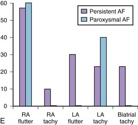
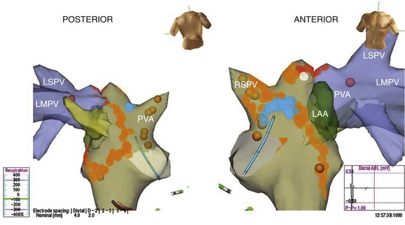
Studies we have conducted in patients with paroxysmal and persistent AF with combined contact bi-atrial and noncontact three-dimensional mapping have allowed analysis of the regional origin of APBs and atrial tachyarrhythmias during spontaneous AF. Evolution into sustained AF and its maintenance have been examined. APBs are most often multi-focal and often bi-atrial in origin in both paroxysmal and persistent AF. One or more APBs can trigger spontaneous AF events in a given patient (Figure 28-14). APBs triggering spontaneous AF demonstrate a wider distribution of origin in persistent AF, with the highest frequency arising from the superior LA and the septum. The onset AT may commence at a location distant from the APB origin (e.g., type 1 flutter) or in proximity to the trigger (e.g., PV trigger initiating re-entrant tachycardia in the posterior left atrium) (see Figure 28-14). Organized atrial tachyarrhythmias are seen in both paroxysmal and persistent AF. At least two atrial tachyarrhythmias, most commonly PV tachycardia and common right atrial flutter, are seen in paroxysmal AF (see Figure 28-14; Videos 28-11 and 28-12), A wider spectrum of atrial tachyarrhythmias can be seen, particularly in persistent AF. This includes focal PV tachycardia; left atrial flutter with macro–re-entry, including mitral isthmus flutter; type 1 isthmus-dependent or type 2 non–isthmus-dependent right atrial flutter; and upper or lower loop flutter of focal AT (see Figure 28-14). Organized atrial tachyarrhythmia distribution in persistent AF (right or left atrial flutter) or tachycardia has demonstrated a wider bi-atrial origin compared with paroxysmal AF. Further, mitral isthmus–dependent left atrial flutter was more prevalent in patients with persistent AF, whereas isthmus-dependent or non–isthmus dependent right atrial flutter was comparable in prevalence in both types of AF. Therefore, AF progression is most likely related to the development of a bi-atrial substrate for the arrhythmia and proliferation of these atrial tachyarrhythmias that result in the persistence of an individual event. These findings bridge the divide between observations obtained with regional catheter recordings and intraoperative findings in humans.
Role of Electrophysiological Evaluation in Therapies for Atrial Fibrillation
Preablation and Ablation Lesion Mapping
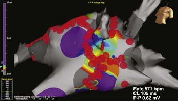
Mapping is performed at electrophysiological evaluation in patients with AF to guide ablative therapies. PV triggers and tachycardia have been targeted by focal, segmental, and isolation procedures. Atrial tachyarrhythmias in either atrium are ablated with linear or focal lesions, and linear lesions are used to compartmentalize the atria. In addition to PV isolation and linear ablation of re-entrant tachycardias detected during electrophysiological testing, more recent mapping and ablation procedures for persistent AF incorporate the ablation of CFAEs as a substrate modification strategy in the catheter ablation of AF.35,43 CFAE regions are targeted with the belief that atrial fractionated potentials indicate areas of nonuniform wavelet propagation and slowed conduction, thus being partly responsible for the perpetuation of AF. Despite early reports of excellent clinical outcomes associated with CFAE-guided left atrial ablation, the clinical outcomes of CFAE ablation have varied widely in other reports, with sinus rhythm maintenance rates ranging between 54% and 74%.44,45 Investigation of the efficacy of CFAE as a stand-alone treatment under three-dimensional mapping system guidance in patients with persistent AF demonstrated that only 9% (2 of 23) of patients who received CFAE ablation were in sinus rhythm after a single ablation procedure without antiarrhythmic medication compared with 41% (22 of 54) of patients with CFAE plus PV isolation ablation procedures.46 The CFAE region has been found to play an important role in the perpetuation of AF as demonstrated by a higher number of focal discharges, frequency of wave breaks and wave fusions, and slower conduction than in non-CFAE regions.47 Several recent technical solutions have been used to allow automatic detection and characterization of CFAEs, ranging from virtual unipolar signals (EnSite) to the fast Fourier transformation (Bard Electrophysiology) of signals from the tip of the ablation catheter up to tiny electrodes on a specialized multi-polar catheter (PentaRay, Biosense Webster). Finally, ablation lesion location and contiguity can be indicated on contour maps (see Video 28-13 and Figures 28-14 and 28-15).
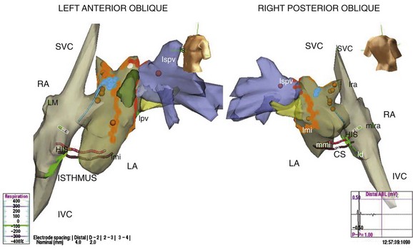
FIGURE 28-15 Three-dimensional map of the right and left atria and pulmonary veins showing venae cavae draining into the right atrium (RA) in addition to the features shown in Figure 28-14 in the same patient. A cavo-tricuspid isthmus linear ablation line is seen in the RA. The coronary sinus is marked by the electrode catheter shown in red. LA, Left atrium; CS, coronary sinus; Isthmus, cavo-tricuspid isthmus; SVC, superior vena cava; lspv, left superor pulmonary vein; lpv, left pulmonary vein; RA, right atrium; IVC, inferior vena cava.
Postablation Mapping
Electrophysiological mapping is performed after catheter ablation to assess the adequacy of the ablation. Focal ablation of PV triggers is assessed by the elimination of PV potentials (see Figure 28-9, D), whereas isolation procedures require demonstration of entrance and exit blocks in the PV. Entrance block evaluation requires coronary sinus or atrial pacing with PV recordings. Exit block evaluation requires PV stimulation with left atrial recordings from the sites on the opposing aspect of the isolation lesions to demonstrate linear lesion integrity (see Videos 28-14 through 30-16 and Figure 28-16).
Electrophysiological Assessment of Interventions: Drugs, Pacing, and Cardioversion Therapy
Drug testing for antiarrhythmic drug efficacy is rarely performed at this time. The feasibility of drug testing in electrophysiological procedures, which use suppression of spontaneous or reproducibly induced AF as an endpoint, has been sporadically demonstrated but has not been widely used. Recent therapeutic focus has been directed at the interaction of pacing modes with arrhythmogenic mechanisms in AF. The effects of pacing can influence the electrical properties of the triggers and the substrate in AF. Acute testing at EPS can demonstrate the impact of these pacing methods. Overdrive atrial pacing can suppress triggers, and multiple-site atrial pacing can result in a reduction in conduction delay with P-wave abbreviation and in the dispersion of atrial refractoriness.48,49 Single-site nonconventional permanent atrial stimulation (e.g., at Bachmann’s bundle) can pre-excite the LA via preferential inter-atrial conduction and shorten the total atrial activation time.50,51 Short-term studies have shown that multiple-site atrial pacing results in modification of the electrophysiological properties of the arrhythmogenic atrial substrate and has been shown to reduce AF induction at EPS.52 Dual-site atrial pacing, in which the high RA and the coronary sinus ostium are used, pre-excites the LA via the posteroinferior atrial connections at this level. It has been shown echocardiographically to reduce P-wave duration by 20% to 30%, advance left atrial activation, and improve left ventricular filling.53,54 Bi-atrial pacing using a left atrial pacing site in combination with standard right atrial pacing has effects similar to those of dual-site right atrial pacing.
The efficacy of internal cardioversion shocks and determination of atrial defibrillation thresholds have both been performed successfully during electrophysiological procedures. These are discussed in more detail in Chapter 90.
Key References
Haissaguere M, Jais P, Shah DC, et al. Spontaneous initiation of atrial fibrillation by ectopic beats originating in the pulmonary veins. N Eng J Med. 1998;339:659-666.
Jais P, Hocini M, Macle L, et al. Distinctive electrophysiological properties of pulmonary veins in patients with atrial fibrillation. Circulation. 2002;106:2479-2485.
Krol RB, Saksena S, Prakash A, Giorgeridze I, Mathew P. Prospective clinical evaluation of a programmed atrial stimulation protocol for induction of sustained atrial fibrillation and flutter. J Interv Cardiol Electrophysiol. 1999;3:19-25.
Marcus GM, Yang Y, Varosy PD, et al. Regional left atrial voltage in patients with atrial fibrillation. Heart Rhythm. 2007;4:138-144.
Nademanee K, McKenzie J, Kosar E, et al. A new approach for catheter ablation of atrial fibrillation: Mapping of the electrophysiologic substrate. J Am Coll Cardiol. 2004;43:2044-2053.
Nault I, Lellouche N, Matsuo S, et al. Clinical value of fibrillatory wave amplitude on surface ECG in patients with persistent atrial fibrillation. J Interv Card Electrophysiol. 2009;26(1):11-19.
Saksena S, Prakash A, Krol RB, Shankar A. Regional endocardial mapping of spontaneous and induced atrial fibrillation in patients with heart disease and refractory atrial fibrillation. Am J Cardiol. 1999;84:880-889.
Saksena S, Skadsberg ND, Rao HB, Filipecki A. Biatrial and three-dimensional mapping of spontaneous atrial arrhythmias in patients with refractory atrial fibrillation. J Cardiovasc Electrophysiol. 2005;16(5):494-504.
Sanders P, Morton JB, Davidson NC, et al. Electrical remodeling of the atria in congestive heart failure: Electrophysiological and electro-anatomical mapping in humans. Circulation. 2003;108:1461-1468.
Schotten U, Duytschaever M, Ausma J, Eijsbouts S, Neuberger HR, Allessie M. Electrical and contractile remodeling during the first days of atrial fibrillation go hand in hand. Circulation. 2003;107(10):1433-1439.
Simpson RJJr., Amara I, Foster RJ, Woelfel A, Gettes LS. Thresholds, refractory periods, and conduction times of the normal and diseased human atrium. Am Heart J. 1988;116:1080-1090.
Skadsberg ND, Nagarakanti R, Saksena S. Biatrial, three-dimensional mapping of human atrial fibrillation: methodology and clinical observations. J Atrial Fibrillation. 2009;1(6):1-13.
Sra J, Bhatia A, Krum D, Akhtar M. Noncontact mapping for radiofrequency ablation of complex cardiac arrhythmias. J Interv Card Electrophysiol. 2001;5(3):327-335.
Stiles MK, Brooks AG, Kuklik P, et al. High-density mapping of atrial fibrillation in humans: Relationship between high-frequency activation and electrogram fractionation. J Cardiovasc Electrophysiol. 2008;19:1245-1253.
Verheule S, Wilson E, Everett T4th, Shanbhag S, Golden C, Olgin J. Alterations in atrial electrophysiology and tissue structure in a canine model of chronic atrial dilation due to mitral regurgitation. Circulation. 2003;107:2615-2622.
1 Kannel WB, Abbott RD, Savage DD, McNamara PM. Epidemiologic features of chronic atrial fibrillation: The Framingham study. N Engl J Med. 1982;306:1018-1022.
2 Scheussler RB, Kawamoto T, Hand DE, et al. Simultaneous epicardial and endocardial activation sequence mapping in the isolated canine right atrium. Circulation. 1993;88:250-263.
3 Haissaguere M, Jais P, Shah DC, et al. Spontaneous initiation of atrial fibrillation by ectopic beats originating in the pulmonary veins. N Engl J Med. 1998;339:659-666.
4 Saksena S, Giorgberidge I, Mehra R, et al. Electrophysiology and endocardial mapping of induced atrial fibrillation in patients with spontaneous atrial fibrillation. Am J Cardiol. 1999;83(2):187-193.
5 Saksena S, Skadsberg ND, Rao HB, Filipecki A. Biatrial and three-dimensional mapping of spontaneous atrial arrhythmias in patients with refractory atrial fibrillation. J Cardiovasc Electrophysiol. 2005;16(5):494-504.
6 Nault I, Lellouche N, Matsuo S, et al. Clinical value of fibrillatory wave amplitude on surface ECG in patients with persistent atrial fibrillation. J Interv Card Electrophysiol. 2009;26(1):11-19.
7 Cuculich PS, Wang Y, Lindsay BD, et al. Noninvasive characterization of epicardial activation in humans with diverse atrial fibrillation patterns. Circulation. 2010;122(14):1364-1372.
8 Fuster V, Ryden LE, Cannom DS, et al. ACC/AHA/ESC 2006 guidelines for the management of patients with atrial fibrillation—a report of the American College of Cardiology/American Heart Association Task Force on Practice Guidelines and the European Society of Cardiology Committee for Practice Guidelines (Writing Committee to Revise the 2001 Guidelines for the Management of Patients With Atrial Fibrillation). J Am Coll Cardiol. 2006;48:e149-e246.
9 European Heart Rhythm AssociationEuropean, Association for Cardio-Thoracic SurgeryCamm AJ, Kirchhof P, Lip GY, et al. Guidelines for the management of atrial fibrillation: The Task Force for the Management of Atrial Fibrillation of the European Society of Cardiology (ESC). Eur Heart J. 2010;31(19):2369-2429.
10 Josephson ME, Seides SF. Electrophysiologic investigation: General concepts. In: Josephson ME, Seides SF, editors. Clinical cardiac electrophysiology: Techniques and interpretations. Philadelphia: Lea & Febiger, 1979.
11 Attuel P, Childers R, Cauchemez B, et al. Failure in the rate adaptation of the atrial refractory period: Its relationship to vulnerability. Int J Cardiol. 1982;2(2):179-197.
12 Attuel P, Coumel P, Janse MJ. The atrium in health and disease, Vol. 9. Futura Publishing, Mt. Kisco, NY, 1989.
13 Haft JI, Lau SH, Stein E, et al. Atrial fibrillation produced by atrial stimulation. Circulation. 1968;37:70.
14 Bauernfeind RA, Swiryn SP, Strasberg B, et al. Electrophysiologic drug testing in prophylaxis of sporadic paroxysmal atrial fibrillation: Technique, application, and efficacy in severely symptomatic pre-excitation patients. Am Heart J. 1982;103(6):941-949.
15 Krol RB, Saksena S, Prakash A, et al. Prospective clinical evaluation of a programmed atrial stimulation protocol for induction of sustained atrial fibrillation and flutter. J Interv Cardiol Electrophysiol. 1999;3:19-25.
16 Simon RD, Rinaldi CA, Baszko A, Gill JS. Electroanatomic mapping of the right atrium with a right atrial basket catheter and three-dimensional intracardiac echocardiography. Pacing Clin Electrophysiol. 2004;27(3):318-326.
17 Meissner A, van Bracht M, Schrage MO, et al. Segmental pulmonary vein isolation in atrial fibrillation: New insights from the high density mesh mapper technique in an electrophysiologically guided approach. J Interv Card Electrophysiol. 2009;25(3):183-192.
18 Maagh P, van Bracht M, Butz T, et al. Eighteen months follow-up of the clinical efficacy of the high density mesh ablator (HDMA) in patients with atrial fibrillation after pulmonary vein isolation. J Interv Card Electrophysiol. 2010;29:43-52.
19 Giorgberidze I, Saksena S, Mongeon L, et al. Effects of high-frequency atrial pacing in atypical atrial flutter and atrial fibrillation. J Interv Card Electrophysiol. 1997;1(2):111-123.
20 Weiss C, Willems S, Risius T, et al. Functional disconnection of arrhythmogenic pulmonary veins in patients with paroxysmal atrial fibrillation guided by combined electroanatomical (CARTO) and conventional mapping. J Interv Card Electrophysiol. 2002;6(3):267-275.
21 Sra J, Bhatia A, Krum D, Akhtar M. Noncontact mapping for radiofrequency ablation of complex cardiac arrhythmias. J Interv Card Electrophysiol. 2001;5(3):327-335.
22 Malchano ZJ, Neuzil P, Cury RC, et al. Integration of cardiac CT/MR imaging with three-dimensional electro-anatomical mapping to guide catheter manipulation in the left atrium: Implications for catheter ablation of atrial fibrillation. J Cardiovasc Electrophysiol. 2006;17:1221-1229.
23 Saksena S, Prakash A, Krol RB, Shankar A. Regional endocardial mapping of spontaneous and induced atrial fibrillation in patients with heart disease and refractory atrial fibrillation. Am J Cardiol. 1999;84:880-889.
24 Skadsberg ND, Nagarakanti R, Saksena S. Biatrial, three-dimensional mapping of human atrial fibrillation: Methodology and clinical observations. J Atrial Fibrillation. 2009;1(6):1-13.
25 Anderson RH, Becker AE, Brechenmacher C, et al. The human atrioventricular junctional area. A morphological study of the A-V node and bundle. Eur J Cardiol. 1975;3(1):11-25.
26 Tebbenjohanns J, Pfeiffer D, Schumacher B, et al. Direct angiography of the coronary sinus: Impact on left posteroseptal accessory pathway ablation. Pacing Clin Electrophysiol. 1996;19(7):1075-1081.
27 Lemery R, Soucie L, Martin B, et al. Human study of biatrial electrical coupling: Determinants of endocardial septal activation and conduction over interatrial connections. Circulation. 2004;110(15):2083-2089.
28 Hordof AJ, Edie R, et al. Electrophysiologic properties and response to pharmacologic agents of fibers from diseased human atria. Circulation. 1976;54:774-779.
29 Gelband H, Bush HL, Rosen MR, et al. Electrophysiologic properties of isolated preparations of human atrial myocardium. Circ Res. 1972;33:293-300.
30 Simpson RJ. Clinical electrophysiology of the normal and diseased human atria. In: Falk RH, Podrid PJ, editors. Atrial fibrillation: Mechanisms and management. New York: Raven Press, Ltd, 1992.
31 Simpson RJJr, Amara I, Foster RJ, et al. Thresholds, refractory periods, and conduction times of the normal and diseased human atrium. Am Heart J. 1988;116:1080-1090.
32 Stiles MK, John B, Wong CX, et al. Paroxysmal lone atrial fibrillation is associated with an abnormal atrial substrate: Characterizing the “second factor,”. J Am Coll Cardiol. 2009;53(14):1182-1191.
33 Sanders P, Morton JB, Davidson NC, et al. Electrical remodeling of the atria in congestive heart failure: Electrophysiological and electro-anatomical mapping in humans. Circulation. 2003;108:1461-1468.
34 Stiles MK, Brooks AG, Kuklik P, et al. High-density mapping of atrial fibrillation in humans: Relationship between high-frequency activation and electrogram fractionation. J Cardiovasc Electrophysiol. 2008;19:1245-1253.
35 Verheule S, Wilson E, Everett T4th, et al. Alterations in atrial electrophysiology and tissue structure in a canine model of chronic atrial dilation due to mitral regurgitation. Circulation. 2003;107:2615-2622.
36 Nademanee K, McKenzie J, Kosar E, et al. A new approach for catheter ablation of atrial fibrillation: Mapping of the electrophysiologic substrate. J Am Coll Cardiol. 2004;43:2044-2053.
37 Marcus GM, Yang Y, Varosy PD, et al. Regional left atrial voltage in patients with atrial fibrillation. Heart Rhythm. 2007;4:138-144.
38 Corradi D, Callegari S, Benussi S, et al. Myocyte changes and their left atrial distribution in patients with chronic atrial fibrillation related to mitral valve disease. Hum Pathol. 2005;36:1080-1089.
39 Kistler PM, Sanders P, Fynn SP, et al. Electrophysiologic and electro-anatomic changes in the human atrium associated with age. J Am Coll Cardiol. 2004;44:109-116.
40 Jais P, Hocini M, Macle L, et al. Distinctive electrophysiological properties of pulmonary veins in patients with atrial fibrillation. Circulation. 2002;106:2479-2485.
41 Rostock T, Steven D, Lutomsky B, et al. Atrial fibrillation begets atrial fibrillation in the pulmonary veins. J Am Coll Cardiol. 2008;51:2153-2160.
42 Schotten U, Duytschaever M, Ausma J, et al. Electrical and contractile remodeling during the first days of atrial fibrillation go hand in hand. Circulation. 2003;107(10):1433-1439.
43 Nademanee K, Schwab MC, Kosar EM, et al. Clinical outcomes of catheter substrate ablation for high-risk patients with atrial fibrillation. J Am Coll Cardiol. 2008;51:843-849.
44 Oral H, Chugh A, Good E, et al. A tailored approach to catheter ablation of paroxysmal atrial fibrillation. Circulation. 2006;113:1824-1831.
45 Oral H, Chugh A, Good E, et al. Radiofrequency catheter ablation of chronic atrial fibrillation guided by complex electrograms. Circulation. 2007;115:2606-2612.
46 Estner HL, Hessling G, Ndrepepa G, et al. Acute effects and long-term outcome of pulmonary vein isolation in combination with electrogram-guided substrate ablation for persistent atrial fibrillation. J Cardiovasc Electrophysiol. 2007;18:151-156.
47 Estner HL, Hessling G, Ndrepepa G, et al. Electrogram-guided substrate ablation with or without pulmonary vein isolation in patients with persistent atrial fibrillation. Europace. 2008;10(11):1281-1287.
48 Yamabe H, Morihisa K, Tanaka Y, et al. Mechanisms of the maintenance of atrial fibrillation: Role of the complex fractionated atrial electrogram assessed by noncontact mapping. Heart Rhythm. 2009;6:1120-1128.
49 Daubert C, Mabo PH, Berder V, et al. Atrial tachyarrhythmias associated with high degree interatrial conduction block: Prevention by permanent atrial resynchronization. Eur JCPE. 1994;1:35-44.
50 Delfaut P, Saksena S, Prakash A, Krol R. Long-term outcome of patients with drug-refractory atrial flutter after single and dual-site atrial pacing for arrhythmia prevention. J Am Coll Cardiol. 1998;32:1900-1908.
51 Papageorgiou P, Monahan K, Boyle NG, et al. Site-dependent intra-atrial conduction delay: Relationship to initiation of atrial fibrillation. Circulation. 1996;94:384-389.
52 Prakash A, Saksena S, Hill M, et al. Acute effects of dual-site right atrial pacing in patients with spontaneous and inducible atrial flutter and fibrillation. J Am Coll Cardiol. 1997;29(5):1007-1014.
53 Bailin SJ, Adler S, Giudici M. Prevention of chronic atrial fibrillation by pacing in the region of Bachmann’s bundle: Results of a multicenter randomized trial. J Cardiovasc Electrophysiol. 2001;12:912-917.
54 Madan N, Saksena S. Long-term rhythm control of drug-refractory atrial fibrillation with “hybrid therapy” incorporating dual-site right atrial pacing, antiarrhythmic drugs, and right atrial ablation. Am J Cardiol. 2004;93(5):569-575.