Chapter 148 Dorsal Thoracic and Lumbar Screw Fixation and Pedicle Fixation Techniques
The popularity of pedicle-screw fixation has significantly increased in the past 2 decades. Pedicle-screw fixation is the only spinal fixation strategy that engages all three columns of the spine. The pedicle screw–bone junction provides the strongest point of attachment of instrumentation to the spine. Thus, pedicle-screw fixation systems can resist motion in all planes.1 In addition, pedicle-screw systems do not require the presence of intact dorsal elements. A historic cohort study with the participation of 303 surgeons and 3498 patients has shown that the use of pedicle screws is a safe and effective form of treatment for spinal disorders.2
History
Toumey3 in 1943 and King4 in 1948 provided the first descriptions of the use of bone screws to obtain internal fixation at the time of fusion. Their techniques for lumbosacral fusion involved passing a screw from medial to lateral across the facet of the involved level bilaterally. Their screws were short and designed to cross the facet joint only. Pseudarthrosis rates were unacceptably high with this method of fixation.5 For this reason, Boucher6 modified their technique by using a longer screw that crossed the facet joint into the pedicle and body of the vertebra below. Boucher6 was the first to use pedicle screws. The pseudarthrosis rate for this technique, including multilevel fusions, was 14% to 17%.5,7 Magerl8 introduced another variation of facet screws in which a screw was passed from one side of the spinous process into the opposite lamina between its two tables, across the facet joint to the base of the transverse process. One disadvantage of the Magerl technique was that it required intact laminae.
Harrington9 initially used facet screws at multiple levels to correct scoliosis in patients with polio but found that this instrumentation eventually failed. This failure led to the development of Harrington instrumentation. Harrington10 first used screws inserted into the pedicles of L5 attached to Harrington distraction rods by heavy stainless steel wire for the reduction and stabilization of spondylolisthesis. Roy-Camille11 was the first to use pedicle screws connected to a dorsal plate. Beginning in 1963, Roy-Camille11 used pedicle-screw fixation in the thoracic and lumbar spine for fractures, for instability after the resection of vertebral tumors, and in lumbosacral fusions. A biomechanical study by Panjabi et al.12 demonstrated that facet-screw fixation stability was relatively low in flexion-extension and lateral bending compared with pedicle-screw fixation systems. Because pedicle fixation systems proved to be biomechanically superior for segmental fixation, numerous variations were developed. The first system that used both screws and hooks, connecting them with rods or plates (i.e., universal spinal instrumentation), was introduced by Cotrel and Dubousset.13
Pedicle-Screw Fixation
The pedicle is the sole bridge between the posterior column and the middle and the anterior columns. Hence, pedicle screws traverse all three columns and as such can rigidly stabilize both the ventral and dorsal aspects of the spine. However, hook-rod systems are affixed only to the posterior spinal elements. For these reasons, pedicle-screw fixation systems, at least in the lumbar spine, are more commonly used than hook-rod systems. Commonly used implant systems are listed in Box 148-1.
Advantages of Pedicle-Screw Fixation
The nature of the pedicle screw–bone junction is much more secure than the wire or hook-bone junction. A single screw provides stability in five planes of motion.1 With transverse connection to the other side, stability is achieved in all six planes of motion.1 The rigidity of pedicle fixation allows for the incorporation of fewer normal motion segments to achieve stabilization of an abnormal level. Because the pedicle represents the strongest point of attachment to the spine, significant forces can be applied to the spine without failure of the bone-metal junction.
Another advantage of pedicle fixation systems is that they do not require intact dorsal elements. Thus, they can be used after laminectomy or traumatic disruption of the laminae, spinous processes, or facets. Pedicle fixation systems also avoid placement of instrumentation in the spinal canal, unlike sublaminar wires and hooks. Additionally, postoperative bracing requirements may be less than with earlier, biomechanically inferior fixation devices. Finally, fusion rates are thought to be improved with the pedicle-screw systems compared with earlier devices,14–16 as well as with noninstrumented fusions.14–17
Pedicle Anatomy
Pedicle size and angulation varies throughout the spinal column. The transverse pedicle width is narrower than the sagittal pedicle width (pedicle height) except in the lower lumbar spine.18 Pedicle width is more important than pedicle height for pedicle-screw placement (Fig. 148-1A). The transverse pedicle width increases from L1 to S1.19 Most of the pedicles below T10 are greater than 7 mm in transverse diameter, and most below L1 are greater than 8 mm in diameter.20 In a study measuring the pedicle diameters with CT, Bernard and Seibert21 found that 20% of pedicles were less than 7 mm at L2, 15.6% at L3, and 1.9% at L4. There were no pedicles less than 7 mm in diameter at L5 and S1. They concluded that all surgeons should perform preoperative CT scans when instrumenting pedicles above L4.
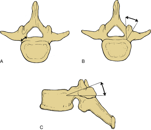
The transverse pedicle angle or coronal plane angulation (Fig. 148-1B) decreases as one descends caudally in the spine until the lumbar region. The angle increases as the lumbar spine is descended. The sagittal pedicle angle (Fig. 148-1C) is steep throughout the midthoracic spine and in the upper lumbar spine.18
The intrathecal nerve roots course along the medial aspect of the pedicle. At T12, the dural sac is 0.2 to 0.3 mm away from the pedicle.18 Below L1, the medial side of the pedicle is almost touching the cauda equina. The nerve root occupies the ventral and rostral one third of the foramen. As a result, violation of the medial or caudal cortex of the pedicle risks injury to the nerve root.
Biomechanics
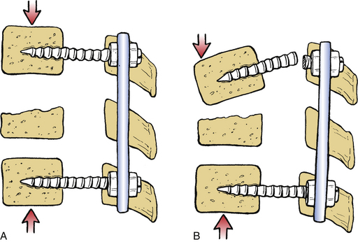
Rigid pedicle fixation techniques, such as rigid plate or screw-rod combinations, apply force to the spine by fixed moment arm cantilever beam fixation.22 A cantilever is a projecting beam that is supported at one end only. It resists axial loads by rigidly buttressing the spine. In the absence of load sharing with the anterior column, significant stress occurs at the screw-plate or screw-rod junction. These constructs tend to fail by screw fracture at this junction.23 However, modifications of the spinal implants (as discussed subsequently) have reduced the incidence of screw breakage.
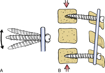
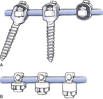
Pedicle-screw fixation systems in which the screws are not rigidly affixed to the plate allow toggling of the screws (Fig. 148-2A). These systems constitute nonfixed moment arm cantilever beam fixation.22 They are unable to resist axial loads without the assistance of an anterior column, which is capable of axial load bearing. Because these systems allow toggling of the screws, they may fail by screw pull-out (Fig. 148-2B).22 For this reason, a fixed moment arm system more effectively resists sagittal translation.
Pedicle-screw fixation can be applied with either a flexion component or an extension component to the applied moment arm, which is usually a rigid pedicle fixator.22 These constructs are used to reduce deformities. Extension moment arm application is their most common mode of application in this regard.
Pedicle fixation techniques may fail during axial loading. This is in part due to a tendency toward the development of a parallelogram-like translational deformity. Toeing-in of the screws and the use of transverse connectors help prevent this mechanism of construct failure.24
Screw Characteristics
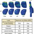
Screw strength is proportional to the cube of the core (minor) diameter.25 The larger the minor diameter, the greater the resistance to screw bending or breakage. The outside (major) diameter is an important factor in screw pull-out resistance. Other important components of pull-out resistance are the thread depth, pitch, and shape. Thread pitch is the distance from one point on the screw thread to the corresponding point on the adjacent thread. Pull-out resistance is directly proportional to the volume of bone between the threads that is determined by the thread depth and pitch. The angle or shape of the thread can affect the interthread volume and hence the pull-out resistance.25
Polyaxial heads have made the pedicle screw more versatile. Therefore, the screws may be easily connected to the rod. However, polyaxial pedicle screws have lower strength than conventional pedicle screws, and they are vulnerable to fatigue failure.26 A biomechanical study has demonstrated that the polyaxial head coupling to the screw is the first to fail and may be a protective feature of the pedicle screw, preventing pedicle-screw breakage.27
Preoperative Planning and Surgery
The patient is placed prone on rolls, a frame, or a table with the abdomen hanging as freely as possible to indirectly decompress the epidural venous plexus. A midline incision is used and carried down to the level of the spinous processes. An adequate incision length facilitates proper trajectory during screw hole preparation and screw placement. All soft tissue is dissected off subperiosteally to minimize blood loss. Muscle dissection should allow for a lateral exposure of the transverse processes on both sides, leaving the intertransverse membrane intact at all levels of the planned instrumentation. A crank retractor helps maintain the lateral exposure. Release of the retractor every 30 minutes reduces muscle necrosis and thereby decreases the risk of infection. The spinal level is identified either anatomically or radiographically, and a decompressive laminectomy is performed if appropriate.
Pedicle Screw Entry Sites and Trajectory
Every spine surgeon should have a thorough knowledge of pedicle anatomy, including the coronal and sagittal plane angulation of the pedicle (see Fig. 148-1). The sagittal pedicle angle increases in the thoracic spine from an average of 0 degrees at T1 to 10 degrees at T8 and then decreases to 0 degrees at T12.28 Usually the L4 sagittal pedicle angle is 0 degrees, and subsequent rostral and caudal levels are associated with progressively greater sagittal angles. The lordotic curvature of the lumbar spine produces a rostral angulation for upper lumbar screws. The L5 pedicle is 5 to 10 degrees caudally inclined. Coronal plane angulation decreases from the cervical spine to the thoracolumbar region and then increases as the lumbar spine is descended. The coronal plane angulation at T1 is 10 to 15 degrees and at T12 is 5 degrees.28 A 10-degree medial angulation is satisfactory at L1. A wider angle in the coronal plane is necessary to avoid lateral penetration of the pedicle in the lower lumbar spine. The coronal plane angle increases approximately 5 degrees per level from L1 to the sacrum.24
In the thoracic spine, the transverse process commonly does not align directly with the pedicle in the axial plane. For this reason, the anatomic landmarks that are used for lumbar pedicle-screw insertion cannot be used in the thoracic spine.28 The transverse process is rostral to the pedicle in the upper thoracic spine and caudal to the pedicle in the lower thoracic spine. The crossover occurs at T6-7.28 Because of the variability of the relationship of the pedicle to the transverse process, fluoroscopic guidance or direct vision and palpation of the pedicle via a laminotomy is recommended for insertion of thoracic pedicles. At the T1 to T3 levels, Louis suggests the use of 4.5-mm diameter screws that are 25 to 30 mm in length.29 At the T4 to T10 levels, screws are usually 4.5 mm in diameter and 30 to 35 mm in length.29
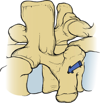
The conventional entry site for pedicle-screw placement in the lumbar region is at the junction of the lateral facet and the transverse process (Fig. 148-3). Although the midline of the transverse process corresponds to the location of the pedicle at L4, this relationship does vary at different lumbar levels. Above L4, the midline of the transverse process is rostral to the pedicle, and at L5, it is an average of 1.5 mm caudal to the pedicle.30
Screw Insertion
After the pedicles have been probed, different-length Steinmann pins or K-wires are placed bilaterally into the pedicular hole at each level. Using different-length pins on each side helps distinguish right and left on the lateral plain radiograph in case the pedicle hole trajectory or depth needs to be corrected. A lateral and an AP radiograph or fluoroscopic image is used to verify the trajectory of the pins. This, however, does not guarantee accurate screw placement.31 With slightly oblique AP views, a pin located in the middle of the pedicle has a characteristic “target sign.” Direct AP views demonstrate the lateral-to-medial orientation of the screws. Excessive medial orientation of the screws seen on an AP film raises the concern of medial penetration of the pedicle by the screw. Lateral imaging is useful to view the depth of penetration into the vertebral body and the sagittal angulation of the trajectory. Ventral screw penetration is usually between 50% and 80% of the AP diameter of the vertebral body. Ventral screw penetration greater than 80% of the vertebral body on a lateral plain radiograph raises the concern of ventral penetration of the vertebral body cortex because of the convex shape of the vertebral bodies. To avoid vascular and visceral injury, the ventral cortex of the vertebral body is not penetrated, although this would enhance the overall strength of the construct.
After confirmation of correct placement of the K-wires or Steinmann pins, the pedicle screw path is tapped if non–self-tapping screws are used. Some tapping screws are hollow and are slid over K-wires into the pedicles. This helps guide the tap along the same trajectory that the pedicle was previously probed. The screw is then guided into the pedicle by its purchase of the threads tapped into the pedicle. However, tapping is less desirable in cancellous bone because tapping weakens the implant-bone junction.25 It is of questionable value in the insertion of pedicle screws because pedicle screws rarely obtain cortical purchase within the pedicle.32 To maximize the bone purchase of the permanent screws, a tap that is smaller in diameter than the screw is used. Tapping is usually not performed at a greater depth than the pedicle.
Percutaneous Screw Placement
Percutaneous pedicle-screw placement to decrease the blood loss and muscle damage as well as to shorten the hospitalization time has increased in popularity. However, such screw placement may increase the operative time and radiation exposure.33,34 The evolution of spinal navigation systems has also contributed to the widespread use of percutaneous screw fixations. Although most such techniques are predominantly used in lumbar spine, there are also reports of using them in the thoracic spine.35
Lehmann et al.34 have compared open versus percutaneous pedicle-screw fixation in an animal model and concluded that percutaneous screw insertion can provide moderate advantages.
Measures for Correct Screw Placement
Although intraoperative fluoroscopy can demonstrate the proper position of the screws, CT provides even more information, but after the fact. Cadaveric studies have demonstrated rates of malpositioned screws to be as high as 21%.36 A variety of techniques have been developed to detect pedicle wall violation and prevent pedicle screw misplacement intraoperatively.
Navigation and CT Guidance
Navigation systems have been created to enhance the surgical accuracy of pedicle-screw placement and to improve clinical outcomes. Computer-assisted fixation and conventional screw fixation have been compared in different studies, and the accuracy and safety of computer-assisted techniques were found to be superior to the conventional techniques.37–41
Modern computer-assisted techniques use frameless stereotaxy as a confirmation tool to identify the target. This may be enhanced by fluoroscopic navigation, the so-called FluoroNav,42 and recently a robotic assistance has been implemented in these systems. A miniature robot has been designed to be mounted on bony landmarks to overcome the limitations of navigation systems.43,44
Fluoroscopically assisted thoracolumbar pedicle-screw placement exposes the spine surgeon to significantly greater radiation levels than other, nonspine procedures that involve the use of a fluoroscope. In fact, dose rates are up to 10 to 12 times greater, primarily because of the increased energy required to image the lumbar spine fluoroscopically and the proximity of the surgeon’s hands to the sources of radiation. Spine surgeons performing fluoroscopically assisted thoracolumbar procedures should monitor their annual radiation exposure. They also use measures to reduce radiation exposure, such as minimizing fluoroscopy time, lead shielding, pulsed image acquisition, and surgeon awareness of high-exposure body and hand positions.45 Computer-navigated systems can reduce the radiation dose.41
Electromyographic Monitoring
Stimulus-evoked electromyographic (EMG) monitoring may be used for detecting a pedicle wall violation. Because the cortical bone has a higher resistivity (low conductivity) to electrical current flow than soft tissues, EMG responses are not elicited with low-stimulation currents in case there is no breakage of the pedicle wall.47 If there is a break in the bony pedicle wall, sufficient electrical current flows through the soft tissue adjacent to the pedicle to cause depolarization of a nearby nerve root, which is easily recorded as a compound action potential by EMG.
False-negative responses occur with this technique. Applying neuromuscular blocking agents, chronically compressed nerve roots may fail to produce EMG activity within the standard stimulation voltages and high resistance of a pedicle-screw implant. For instance, polyaxial screws may have higher resistance values than monoaxial screws.46
Although lumbosacral pedicle-screw placement may be well monitored by lower extremity EMG recording, this has not been a routine for thoracic pedicle-screw fixation. Triggered EMG responses recorded from the rectus abdominis muscles have been successfully used to assess thoracic pedicle-screw placement from T6 to T12,47 and recordings from intercostalis muscles have proved useful in the upper thoracic spine, from T3 to T6.48
Postoperative CT and MRI
Two millimeters or less of medial pedicle perforation or 6 mm or less of lateral pedicle perforation is generally considered safe.49 All neurologic deficits reported have been associated with medial pedicle perforation of greater than 4 mm.50 It means that the safe zone for pedicle penetration is 4 mm.51,52
The malposition of a pedicle screw may be defined as screw placement that causes or has the potential to cause neurologic or vascular complications and/or is associated with suboptimal biomechanical strength due to the malposition. Xu et al. have graded the pedicle perforations: grade I, minimal penetration of the pedicle wall; grade II, less than half of the diameter outside; and grade III, more than half of the diameter outside.52
Screws in Osteoporotic Spine
Holding strength of screws in osteoporotic vertebral bone can be increased by a variety of means, such as by changing the geometric characteristics of the screw, by improving the bone-screw interface with polymethylmethacrylate,53 or by biodegradable calcium phosphate bone substitute augmentation.54 Application of vertebroplasty or kyphoplasty may also be a solution. Hydroxyapatite coating can improve fixation of pedicle screws, with increased pull-out resistance and reduced risk of loosening.55
Complications and Avoidance
Complication rates are as high as 25%. However, most are without permanent clinical consequence. Intraoperative complications occur at a 0.2% to 5% rate.56 According to a cohort study, the complications are usually implant failures (approximately 7%), pedicle fractures (1%), vertebral body penetration (<0.5%), or neurologic deficit (<0.5%).56
In general, early complications after transpedicular stabilization of the spine are unusual and are infrequently associated with permanent morbidity. There is, however, a high proportion of postoperative radiographic failures. Ohlin et al.57 have reported a 40% radiographic failure rate after surgery. Most of them involved screw loosening, angulation, or fracture. Implant removal was necessary within 1 year after operation in about 15% of the cases.
Misplaced Screws
Misplaced screws represent the most frequent pedicle screw complication. The misplacement rate ranges from 1.2% to 28.8% in different series.11,50,58,59 A rostral breach of the pedicle cortex leads to penetration of the intervertebral disc with resultant poor screw fixation. A caudal misplaced screw risks injury to the dura mater and nerve root. Disruption of the medial cortex leads to violation of the spinal canal, which can cause injury to the dura, spinal cord, or nerve roots. Lateral screw placement risks injury to the segmental vessels and poor screw purchase.59,60 A laterally placed screw hole can lead to possible retroperitoneal penetration by the pedicle probe because slippage of the probe off the side of the vertebral body occurs from the sudden lack of resistance to advancement of the probe. Although with postoperative CT approximately 15% of the screws have been reported to be suboptimal,50 nerve root or spinal cord injury is uncommon because of the theoretical safe zones or spaces around the pedicle.
Intraoperative radiographic confirmation of correct screw placement, including the use of fluoroscopy, has still resulted in a high incidence of misplaced screws.61 Therefore, other methods have been developed to ensure accurate placement of screws within the pedicle. Screw placement can be checked electrophysiologically with direct stimulation of the pedicle probe or screw, producing an EMG response peripherally. If this response occurs below the threshold expected for intact cortical bone, the screws may be redirected or removed. Stimulation can be intermittent61–63 or continuous.64,65 Spontaneous EMGs are also monitored, which may alert the surgeon to nerve root irritation from retraction during decompressive procedures, stretching during deformity reductions, or impingement by a pedicle screw.
Interactive frameless stereotaxy with surface reference landmarks has been successfully applied to pedicle fixation of the spine. Preoperative axial CT images of the appropriate spinal segments can be manipulated to assist the surgeon in determining the correct entry point, sagittal and coronal angulation, screw diameter, and length for each pedicle, thus reducing pedicle screw misplacement.66 Frameless stereotactic guidance of pedicle-screw placement is particularly useful when the planned exposure does not allow for palpation of the pedicle at the time of screw insertion (e.g., when a lumbar decompression is not planned).
Nerve Root or Spinal Cord Injury
Neurologic injury during pedicular screw placement is reported to occur in about 2.5% to 7.5% of cases.31 Nerve root injury may result either from improper screw placement or from correction of a deformity with traction on the nerve root or migration of the screw into the neuroforamen or spinal canal. If the symptoms caused by screw malpositioning do not resolve, the instrumentation should be removed or repositioned. In most cases, the radiculopathy improves after removal or repositioning of the misplaced screw.57
Pedicle Fracture
A break in the cortex of the pedicle can result from a misplaced screw, as discussed earlier, or the use of too large a screw. The transverse width of the pedicle is the narrowest dimension of the pedicle and determines the largest-diameter screw that can be used.14,25
Cerebrospinal Fluid Fistulae
The incidence of dural tears is less than 2.5%.60 These are due to spinal canal or neuroforamen penetration. Primary repair of the durotomy, if possible, lessens the risk of a cerebrospinal fluid leak through the wound or pseudomeningocele formation.
Hardware Failure
Mechanical failure has been reported to be between 5% and 31% in different series.57
Screw Breakage
The reported incidence of screw breakage is 0.8% to 24.6%. The incidence of screw breakage and bending is higher in patients in whom major deformity reduction and multilevel fusions were attempted.57,67,68 Rostral screws are more prone to breakage than their caudal counterparts.68 Matsuzaki et al.69 have reported that rostral screw breakage is more common in multilevel fusions but that caudal screw breakage is more common in single-level fusions. Screw breakage after solid fusion is usually asymptomatic and may not require reoperation. However, screw breakage may indicate a pseudarthrosis.29,60,67
The following measures can be taken to avoid screw breakage: (1) choosing the largest-diameter screws that the pedicle can accept20; (2) making the upper portion of a construct longer if nonrigid fixation systems are used, and for fractures in the thoracolumbar junction, using fixation to two levels above the fracture site58; and (3) noting that if the anterior column is severely disrupted, the pedicle screw construct bears all of the load. Lack of anterior column support places significant stress at the screw-rod junction and can result in breakage of the screw at this point. In this situation, a ventral interbody fusion may be required to share the load with the pedicle-screw construct69–71 (Fig. 148-4).
Removing broken pedicle screws is often not a simple task. One of the techniques is to create a groove on the broken head using a 2-mm diamond bur–equipped high-speed drill and a minus screwdriver.72,73 Also, a friction technique has been described.74
Screw Pull-out
Screw pull-out increases with decreasing bone mineral density.23,75 A solid screw purchase in osteoporotic bone is not easily achieved, and therefore osteoporotic bone is a relative contraindication to the use of pedicle screws. Hooks or wires provide superior pull-out resistance compared with pedicle screws in osteoporotic bone. This is due to the greater cortical bone-metal surface contact.76 Instrumentation in patients with osteoporosis should include “extra” levels, with multiple points of fixation.
The length of the screw is important regarding screw pull-out. Lumbar screws should be placed approximately to a depth of two thirds of the vertebral body on the lateral radiographs. This maximizes depth of penetration without risking bicortical purchase in the lumbar area.77
The use of pedicle-screw fixation systems that rigidly connect the screw to the plate or rod resist screw pull-out by not allowing toggling of the screws.22 Screw toe-in results in greater pull-out resistance and translational deformity prevention if the two sides of the construct are rigidly affixed to each other. In this configuration, the screw pull-out is prohibited by its toed-in counterpart.78
Placement of a sublaminar hook caudal to a pedicle screw increases the pull-out resistance of the construct. This configuration is made possible by the location of the lamina approximately one-half segment below the pedicle. The pedicle screw–sublaminar hook construct resists pull-out while maintaining the rotation-, flexion-, and extension-resisting capabilities of the pedicle screw.76,78 This is not appropriately applied at the most caudal segment of the construct.
Loss of Correction
Loss of correction may occur after the reduction of a traumatic or congenital kyphosis, particularly if overdistraction or forceful correction was performed during the operation. The strength of the anterior column is important. If there is significant compromise of the anterior column, ventral grafting and fusion should be added. Otherwise, a loss of correction (kyphosis) may develop, resulting in screw angulation or breakage at the screw–longitudinal member junction (see Fig. 148-4).70,77
Universal Spinal Instrumentation Systems
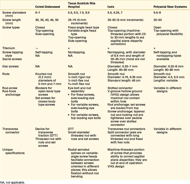
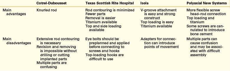
The first USI prototype was the Cotrel-Dubousset (CD) device.13 This was followed by the Texas Scottish Rite Hospital (TSRH)79,80 and the Isola5,81 systems. The CD system has been updated via the compact Cotrel-Dubousset (CCD)82 and the CD Horizon spinal systems. The characteristics of the CD, TSRH, and Isola systems, and polyaxial screw systems as well as their advantages and disadvantages, are depicted in Tables 148-1 and 148-2.
TABLE 148-1 Specifications of Screws and Longitudinal Members of Universal Spinal Instrumentation Systems
Cotrel-Dubousset System
CD instrumentation is the oldest of the universal systems. It was designed by Cotrel and Dubousset in France between 1978 and 1982. It was first designed for correction of pediatric scoliosis.13 This system provides a rigid three-dimensional short-segment fixation without the need for sublaminar wires in the spinal canal. It uses hooks and screws as anchors, coupled to a rod by a set screw. In the first version of the CD system, set screws of the closed-body type were broken (twisted off) at the end of the instrumentation. This makes the revision or removal of the instrumentation very difficult.71 The CD system uses self-tapping pedicle screws, whereas the other systems use nontapping screws. The CD system has a lateral connector that facilitates the screw-rod connection in the presence of coronal plane deformities (Fig. 148-5).
Compact Cotrel-Dubousset System
The original CD instrumentation presented disadvantages such as an unnecessary number of implant components and a permanent implant locking system. Therefore, a new version, the CCD, was developed. The instrument set and the implants were streamlined, and an improved locking system enabled easy removal.82
Texas Scottish Rite Hospital System
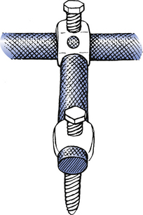
Perhaps the most important and unique feature of the TSRH system is the variable-angle screw that facilitates coupling to the rod regardless of the angle of screw insertion (Fig. 148-6A). The top-loading couplers are available with varying thickness, which accommodates coronal plane offsets and minimizes the need to contour the rod in this dimension (Fig. 148-6B).
Isola System
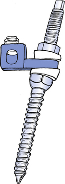
The Isola system is one of the newest of the USI fixators. A unique feature of the screws of the Isola system is a machine-threaded portion that allows the correction of sagittal deformities by placing straight or angled washers over the threads.82 Slotted plate connectors couple the rods to the screws. The connectors are first placed on the rods, and then the slotted portion of the plate is placed over the machine-threaded portion of the screw. Plate lengths vary. This minimizes the need to contour the rod to accommodate coronal plane deformities (Fig. 148-7).
Modern Polyaxial Systems
The versatility of fixation systems has increased in many ways. Also, low-profile systems for slim patients and for children have been developed. Stainless steel alloys essentially have been replaced by alloys, most commonly alloys of titanium. Reduced profile and implant volume, with greater ergonomy and ease of application, are the predominant features of the more modern systems.
Bai B., Kummer F.J., Spivak J. Augmentation of anterior vertebral body screw fixation by an injectable, biodegradable calcium phosphate bone substitute. Spine (Phila Pa 1976). 2001;26:2679-2683.
Darden B.V.II, Wood K.E., Hatley M.K., et al. Evaluation of pedicle screw insertion monitored by intraoperative evoked electromyography. J Spinal Disord. 1996;9:8-16.
Fessler R.G., Sturgill M. Utilization of the Texas Scottish Rite Hospital Universal System for stabilization of the thoracic and lumbar spine. In: Fessler R.G., Haid R.W., editors. Current techniques in spinal stabilization. New York: McGraw-Hill; 1996:273-285.
Harrington P.R., Dickson J.H. Spinal instrumentation in the treatment of severe progressive spondylolisthesis. Clin Orthop Relat Res. 1976;117:157-163.
Kalfas I.H., Kormos D.W., Murphy M.A., et al. Application of frameless stereotaxy to pedicle screw fixation of the spine. J Neurosurg. 1995;83:641-647.
Louis R. Fusion of the lumbar and sacral spine by internal fixation with screw plates. Clin Orthop Relat Res. 1986;203:18-33.
McCormack T., Karaikovic E., Gaines R.W. The load sharing classification of spine fractures. Spine (Phila Pa 1976). 1994;19:1741-1744.
Rengachary S.S., Flores E. Segmental fixation of the lumbosacral spine using the Isola/VSP system. In: Fessler R.G., Haid R.W., editors. Current techniques in spinal stabilization. New York: McGraw-Hill; 1996:367-378.
Resnick D.K. Prospective comparison of virtual fluoroscopy to fluoroscopy and plain radiographs for placement of lumbar pedicle screws. J Spinal Disord Tech. 2003;16:254-260.
Steffee A.D. The variable screw placement system with posterior lumbar interbody fusion. In: Zin P.M., Gill K., editors. Lumbar interbody fusion: principles and techniques in spine surgery. Gaithersburg, MD: Aspen Press; 1989:81-93.
Vaccaro A.R., Garfin S.R. Internal fixation (pedicle screw fixation) for fusion of the lumbar spine. Spine (Phila Pa 1976). 1995;20(Suppl 24):157S-165S.
1. Asher M.A. Lumbopelvic fixation with the Isola Spinal Implant System. In: Margulies J.Y., Floman Y., Farcy J.C., et al, editors. Lumbosacral and spinopelvic fixation. Philadelphia: Lippincott-Raven; 1996:215-238.
2. Yuan H.A., Garfin S.R., Dickman C.A., et al. A historical cohort study of pedicle screw fixation in thoracic, lumbar and sacral spinal fusions. Spine (Phila Pa 1976). 1994;19:S2279-S2296.
3. Toumey J.W. Internal fixation in fusion of the lumbosacral joint. Lahey Clin Bull. 1943;3:188-191.
4. King D. Internal fixation for lumbosacral fusion. J Bone Joint Surg [Am]. 1948;30:560-565.
5. Pennal G.L., McDonald G.A., Dale G.G. A method of spinal fusion using internal fixation. Clin Orthop Relat Res. 1964;35:86-94.
6. Boucher H.H. A method of spinal fusion. J Bone Joint Surg [Br]. 1959;41:248-259.
7. Graham C.E. Lumbosacral fusion using internal fixation with a spinous process for the graft. Clin Orthop Relat Res. 1979;140:72-77.
8. Magerl F.P. Stabilization of the lower thoracic and lumbar spine with external skeletal fixation. Clin Orthop Relat Res. 1984;189:125-141.
9. Harrington P.R. The history and development of Harrington instrumentation. Clin Orthop Relat Res. 1988;227:3-5.
10. Harrington P.R., Dickson J.H. Spinal instrumentation in the treatment of severe progressive spondylolisthesis. Clin Orthop Relat Res. 1976;117:157-163.
11. Roy-Camille R., Saillant G., Mazel C. Internal fixation of the lumbar spine with pedicle screw plating. Clin Orthop Relat Res. 1986;203:7-17.
12. Panjabi M.M., Yamamoto I., Oxland T.R. Biomechanical stability of five pedicle screw fixation systems in a human lumbar spine instability model. Clin Biomech. 1991;6:197-205.
13. Cotrel Y., Dubousset J., Guillaumat M. New universal instrumentation in spine surgery. Clin Orthop Relat Res. 1988;227:10-23.
14. Stillerman C.B., Gruen J.P. Universal spinal instrumentation fixation. In: Benzel E.C., editor. Spinal instrumentation. Park Ridge, IN: American Association of Neurological Surgeons; 1994:147-174.
15. Stillerman C.B., Gruen J.P., Roy R. Thoracic and lumbar fusion: techniques for posterior stabilization. In: Menezes A., Sonntag V.K.H., editors. Principles of spinal surgery. New York: McGraw Hill; 1996:1199-1224.
16. Zdeblick T.A. A prospective, randomized study of lumbar fusion. Spine (Phila Pa 1976). 1994;18:983-991.
17. Lorenz M., Zindrick J., Schwaegler P., et al. Comparison of single level fusions with and without hardware. Spine (Phila Pa 1976). 1991;16:S455-S458.
18. Benzel E.C. Biomechanically relevant anatomy and material properties of the spine and associated elements. In: Benzel E.C., editor. Biomechanics of spine stabilization: principles and clinical practice. New York: McGraw-Hill; 1995:3-16.
19. Zindrick M.R., Wiltse L.L., Widell E.H., et al. A biomechanical study of intrapedicular screw fixation of the lumbosacral spine. Clin Orthop Relat Res. 1986;203:99-112.
20. Krag M.H., Beynnon B.D., Pope M.H., et al. An internal fixator for posterior application to short segments of the thoracic, lumbar, or lumbosacral spine: design and testing. Clin Orthop Relat Res. 1986;203:75-98.
21. Bernard T.N., Seibert C.E. Pedicle diameter determined by computer tomography: its relevance to pedicle fixation in the lumbar spine. Spine (Phila Pa 1976). 1992;17:S160-S163.
22. Benzel E.C. Mechanical (quantitative) attributes of spinal implants: constructs types. In: Benzel E.C., editor. Biomechanics of spine stabilization: principles and clinical practice. New York: McGraw-Hill; 1995:151-162.
23. Yoganandan N., Larson S.J., Pintar F., et al. Biomechanics of lumbar pedicle screw/plate fixation in trauma. Neurosurgery. 1990;27:873-881.
24. Krag M.H., Weaver D.L., Beynnon B.D., Haugh L.D. Morphometry of the thoracic and lumbar spine related to transpedicular screw placement for surgical spinal fixation. Spine (Phila Pa 1976). 1988;13:27-32.
25. Benzel E.C. Implant-bone interfaces. In: Benzel E.C., editor. Biomechanics of spine stabilization: principles and clinical practice. New York: McGraw-Hill; 1995:127-134.
26. Stanford R.E., Loefler A.H., Stanford P.M., et al. Multiaxial pedicle screw designs: static and dynamic mechanical testing. Spine (Phila Pa 1976). 2004;29:367-375.
27. Fogel G.R., Reitman C.A., Liu W., et al. Physical characteristics of polyaxial-headed pedicle screws and biomechanical comparison of load with their failure. Spine (Phila Pa 1976). 2003;28:470-473.
28. McCormack B.M., Benzel E.C., Adams M.S., et al. Anatomy of the thoracic pedicle. Neurosurgery. 1995;37:303-308.
29. Louis R. Application of the Louis system for thoracolumbar and lumbosacral spine stabilization. In: Fessler R.G., Haid R.W., editors. Current techniques in spinal stabilization. New York: McGraw-Hill; 1996:399-407.
30. Ebraheim N.A., Rollins J.R.Jr., Xu R., et al. Projection of the lumbar pedicle and its morphometric analysis. Spine (Phila Pa 1976). 1996;21:1296-1300.
31. Esses S.I., Botsford D.J., Wright T., et al. Operative treatment of spinal fractures with the AO internal fixator. Spine (Phila Pa 1976). 1991;16:S146-S150.
32. Misenhimer G.R., Peek R.D., Wiltse L.L., et al. Anatomic analysis of pedicle cortical and cancellous diameter as related to screw size. Spine (Phila Pa 1976). 1989;14:367-372.
33. Dickerman R.D., Reynolds A.S., Tackett J., et al. Percutaneous pedicle screws significantly decrease muscle damage and operative time: surgical technique makes a difference!. Eur Spine J. 2008;17:1398.
34. Lehmann W., Ushmaev A., Rueker A., et al. Comparison of open versus percutaneous pedicle screw insertion in a sheep model. Eur Spine J. 2008;4:97-103.
35. Hubbe U., Kogias E., Vougioukas V.I. Image-guided percutaneous trans-pedicular screw fixation of the thoracic spine. A clinical evaluation. Acta Neurochir. 2009;151:545-549.
36. Vaccaro A.R., Garfin S.R. Internal fixation (pedicle screw fixation) for fusion of the lumbar spine. Spine (Phila Pa 1976). 1995;20(Suppl 24):157S-165S.
37. Amiot L.P., Lang K., Putzier M., et al. Comparative results between conventional and computer-assisted pedicle screw installation in the thoracic, lumbar, and sacral spine. Spine (Phila Pa 1976). 2000;25:606-614.
38. Laine T., Lund T., Ylikoski M., et al. Accuracy of pedicle screw insertion with and without computer assistance: a randomised controlled clinical study in 100 consecutive patients. Eur Spine J. 2000;9:235-240.
39. Resnick D.K. Prospective comparison of virtual fluoroscopy to fluoroscopy and plain radiographs for placement of lumbar pedicle screws. J Spinal Disord Tech. 2003;16:254-260.
40. Schwarzenbach O., Berlemann U., Jost B., et al. Accuracy of computer-assisted pedicle screw placement. An in vivo computed tomography analysis. Spine (Phila Pa 1976). 1997;22:452-458.
41. Zwingmann J, Konrad G, Kotter E, et al: Computer-navigated iliosacral screw insertion reduces malposition rate and radiation exposure. Clin Orthop Relat Res 467:1833-1838, 2009.
42. Rampersaud Y.R., Pik J.H., Salonen D., Farooq S. Clinical accuracy of fluoroscopic computer-assisted pedicle screw fixation: a CT analysis. Spine (Phila Pa 1976). 2005;30:E183-E190.
43. Lieberman I.H., Togawa D., Kayanja M.M., et al. Bone-mounted miniature robotic guidance for pedicle screw and translaminar facet screw placement: part I–technical development and a test case result. Neurosurgery. 2006;59:641-650.
44. Shoham M., Burman M., Zahavi E., et al. Bone-mounted miniature robot for surgical procedures: concept and clinical applications. IEEE Trans Rob Autom. 2003;19:893-901.
45. Rampersaud Y.R., Foley K.T., Shen A.C., et al. Radiation exposure to the spine surgeon during fluoroscopically assisted pedicle screw insertion. Spine (Phila Pa 1976). 2000;25:2637-2645.
46. Anderson D.G., Wierzbowski L.R., Schwartz D.M., et al. Pedicle screws with high electrical resistance: a potential source of error with stimulus-evoked EMG. Spine (Phila Pa 1976). 2002;27:1577-1581.
47. Raynor B.L., Lenke L.G., Kim Y., et al. Can triggered electromyograph thresholds predict safe thoracic pedicle screw placement? Spine (Phila Pa 1976). 2002;27:2030-2035.
48. Rodriguez-Olaverri J.C., Zimick N.C., et al. Using triggered electromyographic threshold in the intercostal muscles to evaluate the accuracy of upper thoracic pedicle screw placement (T3–T6). Spine (Phila Pa 1976). 2008;33:E194-E197.
49. Belmont P.J.Jr., Klemme W.R., Robinson M., Polly D.W.Jr. Accuracy of thoracic pedicle screws in patients with and without coronal plane spinal deformities. Spine (Phila Pa 1976). 2002;27:1558-1566.
50. Gertzbein S.D., Robbins S.E. Accuracy of pedicular screw placement in vivo. Spine (Phila Pa 1976). 1990;15:11-14.
51. Suk S.I., Kim W.J., Lee S.M., et al. Thoracic pedicle screw fixation in spinal deformities: are they really safe? Spine (Phila Pa 1976). 2001;15(26):2049-2057.
52. Xu R., Ebraheim N.A., Shepherd M.E., et al. Thoracic pedicle screw placement guided by computed tomographic measurements. J Spinal Disord. 1999;12(3):222-226.
53. Becker S., Chavanne A., Spitaler R., et al. Assessment of different screw augmentation techniques and screw designs in osteoporotic spines. Eur Spine J. 2008;17:1462-1469.
54. Bai B., Kummer F.J., Spivak J. Augmentation of anterior vertebral body screw fixation by an injectable, biodegradable calcium phosphate bone substitute. Spine (Phila Pa 1976). 2001;26:2679-2683.
55. Sandén B., Olerud C., Larsson S. Hydroxyapatite coating enhances fixation of loaded pedicle screws: a mechanical in vivo study in sheep. Eur Spine J. 2001;10:334-339.
56. Garfin S.R. Summation. Spine (Phila Pa 1976). 1994;19:S2300-S2305.
57. Ohlin A., Karrlson M., Duppe H., et al. Complications after transpedicular stabilization of the spine. A survivorship analysis of 163 cases. Spine (Phila Pa 1976). 1994;19:2774-2779.
58. Krag M.H. Biomechanics of thoracolumbar spinal fixation: a review. Spine (Phila Pa 1976). 1991;16:S84-S99.
59. West J.L.III, Ogilvie J.W., Bradford D.S. Complications of the variable screw plate pedicle screw fixation. Spine (Phila Pa 1976). 1991;16:576-579.
60. Chozick B.S., Toselli R. Complications of spinal instrumentation. In: Benzel E.C., editor. Spinal instrumentation. Park Ridge, IN: American Association of Neurological Surgeons; 1994:257-274.
61. Owen J.H., Kostuik J.P., Gornet M., et al. The use of mechanically elicited electromyograms to protect nerve roots during surgery for spinal degeneration. Spine (Phila Pa 1976). 1994;19:1704-1710.
62. Clements D.H., Morledge D.E., Martin W.H., et al. Evoked and spontaneous electromyography to evaluate lumbosacral pedicle screw placement. Spine (Phila Pa 1976). 1996;21:600-604.
63. Darden B.V.II, Wood K.E., Hatley M.K., et al. Evaluation of pedicle screw insertion monitored by intraoperative evoked electromyography. J Spinal Disord. 1996;9:8-16.
64. Calancie B., Madsen P., Lebwohl N. Stimulus-evoked EMG monitoring during transpedicular lumbosacral spine instrumentation. Spine (Phila Pa 1976). 1994;19:2780-2786.
65. Rose R.D., Welch W.C., Balzer J.R., et al. Persistently electrified pedicle stimulation instruments in spinal instrumentation. Technique and protocol development. Spine (Phila Pa 1976). 1997;22:334-343.
66. Kalfas I.H., Kormos D.W., Murphy M.A., et al. Application of frameless stereotaxy to pedicle screw fixation of the spine. J Neurosurg. 1995;83:641-647.
67. Davne S.H., Myers D.L. Complications of lumbar spinal fusion with transpedicular instrumentation. Spine (Phila Pa 1976). 1992;17:S184-S189.
68. McAfee P.C., Weiland D.J., Carlow J.J. Survivorship analysis of pedicle spinal instrumentation. Spine (Phila Pa 1976). 1991;16:S422-S427.
69. Matsuzaki H., Tokuhashi Y., Matsumoto F., et al. Problems and solutions of pedicle screw plate fixation of lumbar spine. Spine (Phila Pa 1976). 1990;15:1159-1165.
70. Whitecload T.S.III, Butler J.C., Cohen J.L., et al. Complications with the variable spinal plating system. Spine (Phila Pa 1976). 1989;14:472-476.
71. McCormack T., Karaikovic E., Gaines R.W. The load sharing classification of spine fractures. Spine (Phila Pa 1976). 1994;19:1741-1744.
72. Duncan J.D., MacDonald J.D. Extraction of broken pedicle screws: technical note. Neurosurgery. 1998;42:1399-1400.
73. Miyamoto K., Shimizu K., Kouda K., et al. Removal of broken pedicle screws: technical note. J Neurosurg. 2001;95:150-151.
74. Di Lorenzo N., Conti R., Romoli S. Retrieval of broken pedicle screws by friction technique: technical note. J Neurosurg. 2000;92:114-116.
75. Yamagata M., Kitahara H., Minami S., et al. Mechanical stability of the pedicle screw fixation systems for the lumbar spine. Spine (Phila Pa 1976). 1994;17:S51-S54.
76. Coe J.D., Warden K.E., Herzig M.A., et al. Influence of bone mineral density on the fixation of thoracolumbar implants: a comparative study of transpedicular screws, laminar hooks, and spinous process wires. Spine (Phila Pa 1976). 1990;15:902-907.
77. McCormick P.C. Utilization of the Cotrel-Dubousset instrumentation system for stabilization of the spine. In: Fessler R.G., Haid R.W., editors. Current techniques in spinal stabilization. New York: McGraw-Hill; 1996:287-296.
78. Ruland C.M., McAfee P.C., Warden K.E., et al. Triangulation of pedicular instrumentation. A biomechanical analysis. Spine (Phila Pa 1976). 1991;16:S270-S276.
79. Benzel E.C., Baldwin N.G., Ball P.A. Texas Scottish Rite Hospital hook-rod spinal fixation. In: Hitchon P.W., Traynelis V.C., Rengachary S.S., editors. Techniques in spinal fusion and stabilization. New York: Thieme Medical; 1995:229-239.
80. Johnston C.E.II, Herring A., Ashman R. Texas Scottish Rite Hospital (TSRH) universal spinal instrumentation system. In: An H.S., Cotler J.M., editors. Spinal instrumentation. Baltimore: Williams & Wilkins; 1992:127-165.
81. Asher M.A., Strippgen W.E., Heinig C.F., Carson W.L. Isola spinal system: principles, design, and applications. In: An H.S., Cotler J.M., editors. Spinal instrumentation. Baltimore: Williams & Wilkins; 1992:325-351.
82. Gillet P. Utilization of the compact Cotrel-Dubousset system for stabilization of the thoracolumbar and lumbar spine. In: Fessler R.G., Haid R.W., editors. Current techniques in spinal stabilization. New York: McGraw-Hill; 1996:297-308.