[level-membership-for-neurosurgery-category]
Chapter 147 Dorsal Subaxial Cervical Instrumentation Techniques
Subaxial cervical instability has many causes, including trauma, degenerative disease, neoplasm, and infection. Instability may also develop after spinal canal or foraminal decompression or in conjunction with tumor resection. Historically, the management of such instability first consisted of extended immobilization with traction or an orthosis to maintain proper alignment until bony and/or ligamentous healing transpired. Despite the usefulness of these treatment modalities, they predispose patients to a variety of medical complications. Furthermore, such management does not always result in long-term spinal stability. In 1891, Hadra1 described the role of spinous process wiring to treat traumatic and inflammatory cervical instability. Subsequently a multitude of cervical fusion techniques were reported that used wires secured to the spinous processes, laminae, and/or facets. Cervical wiring techniques are important in the management of cervical instability.
Indications for Surgery
Trauma
Trauma is a common indication for dorsal cervical stabilization.2 The primary management of cervical spine injuries consists of realignment (when necessary), decompression of the neural elements (when indicated), and stabilization. In the setting of trauma, if the spine is in good alignment and no decompression is necessary, external immobilization may be all that is required to protect the neural elements while healing occurs. This is particularly true when the major cause of the instability is bony injury. Primary ligamentous instability is much less likely to resolve after immobilization; hence early surgical stabilization is often an appropriate consideration in the management of these injuries.
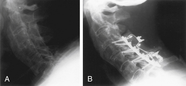
Instrumentation of the dorsal cervical spine should be considered seriously in all trauma victims who require an open reduction or a dorsal cervical decompression. Persistent dorsal ligamentous instability is most appropriately treated by dorsal surgical stabilization; in fact, it is not unreasonable to offer patients with severe ligamentous injuries internal fixation as an alternative to halo immobilization. Fixation across the afflicted level only is usually successful in achieving long-term stabilization in patients with dorsal ligamentous injuries; however, consideration should be given toward incorporating additional levels into the construct in the setting of severe instability3 (Fig. 147-1). Bony cervical spinal injuries may also be stabilized by using dorsal instrumentation. In particular, cervical lateral mass instrumentation may be used in the presence of laminar and spinous process fractures that often preclude the use of many other types of dorsal fixation.
Extension instability and injuries of the ventral axial spine have been managed successfully by using multilevel dorsal fixation; however, a ventral approach is usually more appropriate. This is particularly true if the spinal canal is compromised from bone or disc fragments or when a burst fracture is associated with 25-degree or greater kyphosis.3,4
Spondylosis
Dorsal cervical instrumentation is also useful in the management of spondylotic disease. Proper instrumentation at the time of initial decompression in patients with abnormal segmental motion or absent lordosis markedly decreases their risk of developing postlaminectomy kyphosis. In these cases, instrumentation and subsequent fusion are important to prevent further problems; when a kyphotic deformity has occurred, treatment with dorsal instrumentation alone does not usually provide the optimum result. Almost invariably, ventral spinal reconstruction is the necessary first step needed to correct or halt progressive postlaminectomy kyphotic deformities; dorsal fixation may then be considered as an adjunctive measure in select patients. Dorsal fusion may provide a more successful means of treating patients who experience symptoms from failed ventral arthrodesis than a second ventral surgery.5,6 In highly selected cases of severe ventral and dorsal spinal incompetence, a combined or staged “360-degree” operation may be indicated.
General Considerations
Imaging
CT provides better bony detail than MRI and therefore is more useful to define fractures. MRI often complements CT in the trauma setting because of its ability to define ligamentous injury.7 Both modalities are useful in assessing the extent of tumor involvement in patients with metastatic malignancies. CT myelograms should be considered in patients who are unable to have MRIs or when the MRI is equivocal, such as when a previous instrumentation artifact obscures adequate visualization. CT allows for evaluation of the transverse foramina and, by proxy, the vertebral artery. Localization of the vertebral artery is important in surgical planning for placement of screws in the cervical spine.
Intraoperative Monitoring
Neurophysiologic monitoring can be used to monitor the spinal cord integrity during surgery. Options include monitoring somatosensory-evoked potentials (SSEPs) and motor-evoked potentials (MEPs). SSEPs represent signal-averaged data often over several minutes and monitor the spinal cord dorsal columns. MEPs are usually associated with patient motion during recording and are therefore obtained episodically. Special anesthesia considerations exist with intraoperative monitoring. The usefulness of intraoperative monitoring is established for intradural tumors and vascular malformations but is unclear for other cervical spine surgeries. The authors rarely employ such monitoring (barring experimental protocols) in treating cervical pathology other than intrinsic tumors, vascular malformations, or severe deformities.
Tracheal Intubation
Awake fiberoptic intubations should be considered in patients with significant preoperative instability. Fiberoptic intubation allows for securing the airway with minimal manipulation and extension of the cervical spine. Awake intubation facilitates awake positioning of the patient. Careful intubation under general anesthesia is an alternative to an awake intubation. The head must be held in the neutral position or traction employed if there is a concern for preoperative instability. External orthoses, manual in-line immobilization, and/or axial traction may be used to limit the motion of unstable segments during intubation and positioning.8–10
Bony Fusion
Corticocancellous bone may be obtained from the cervical laminae if a laminectomy is performed. If spinal canal decompression is not warranted, adequate bone for a facet fusion may be obtained from the cervical or upper thoracic spinous processes. Another alternative is to harvest bone from the dorsal iliac crest or a rib.11 Corticocancellous bone is placed over the dorsal elements.
Cerebrospinal Fluid Leak
If cerebrospinal fluid (CSF) is noted at any time during the procedure, the site of the leak should be determined. Ideally, all dural defects are closed primarily. If a dural violation cannot be directly repaired, such as may be the case if the defect is located laterally or ventrally, fibrin glue may help seal the leak.12 If a watertight dural closure is not achieved, wound drains should be avoided. In some situations, lumbar CSF drainage will help decrease the risk of developing a CSF fistula or a pseudomeningocele.
Wound Closure
The wound should be closed in layers with interrupted suture. Removal of the dorsal portion of a prominent C7 and/or T1 spinous process can be extremely helpful for limiting wound tension in slender patients. If local irradiation has been performed or is anticipated, nonabsorbable suture should be considered, at least for the fascial closure. It may be wise to close the entire wound with such suture in these patients. Wound drain placement should be individualized. Some completely dry wounds need no drain; however, if there is oozing from the raw bone surfaces, it may be prudent to place a drain. This is particularly important if a laminectomy has been performed. All wound drains should be tunneled and exit via a separate stab incision.
Dorsal Subaxial Cervical Instrumentation Techniques
Luque Instrumentation
Stainless steel pediatric Luque L-rods and Luque rectangles (Zimmer, Warsaw, IN) may be used to stabilize the cervical spine.13 The rectangular construct provides greater torsional stability than the L-rods and is therefore preferable. These devices are not indicated for one- or two-level fixation but rather multilevel stabilization procedures. Ideally, both the rods and the rectangles are segmentally secured to every level traversed; however, this is not always necessary. Luque instrumentation can be used to bridge dorsal element defects, such as may occur with metastatic malignancies; however, when using this technique, at least two levels of segmental fixation must be obtained above and below the incompetent region. These devices are most useful for fixation extending to the upper cervical spine or crossing the cervicothoracic junction.
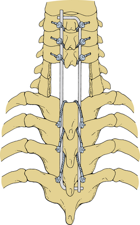
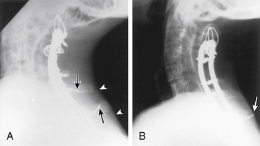
Securing the Luque instrumentation to the spine is performed in steps. First, the precontoured device is carefully introduced into the wound, and the previously placed cables or wires are positioned around it. L-rods are placed such that the short arm of each L lies beneath the end of the opposite long arm (Fig. 147-2). The wires or cables are tightened sequentially. Tightening is done gradually so that opposing levels are tightened concurrently, thereby minimizing torsional forces. Cables can generally be tightened to 6 to 8 inch-pounds of torque, but this value should be individualized. Excess wire or cable should be trimmed appropriately before closure to avoid future wound problems (Fig. 147-3). Before closure of the wound, bone grafts may be laid on the laminae and/or the lateral masses.
Compression Clamps
Another method of internal fixation that requires intact laminae to stabilize adjacent levels across one or two motion segments is the interlaminar compression clamp. These devices include the Halifax clamp (American Medical Electronics, Inc., Richardson, TX) and Apofix (Medtronic Sofamor Danek, Memphis, TN).14,15 One of the few indications for placement of this device is isolated dorsal ligamentous instability. Although their use in patients with facet injuries and even linear laminar fractures has been reported, they may not be indicated if there is any significant bony injury.2 Other contraindications to placement of laminar compression clamps are the presence of significant vertebral body injury or facet fractures. Lack of ventral column support should be treated with ventral reconstruction, and loss of facet integrity will predispose the cervical spine to rotatory instability that this device is incapable of correcting.
Lateral exposure need only be carried to the medial or central portion of the facet. The pertinent laminae, spinous processes, and dorsal surface of the facets are denuded of periosteum and their bony surfaces prepared, as mentioned previously. The ligamentum flavum is detached from the laminae to be instrumented. For the Halifax instrumentation, appropriately sized clamps are selected and placed temporarily into the wound to estimate the minimal amount the jaws must be opened to pass over the laminae to be instrumented. The clamps are removed from the wound and adjusted accordingly. This maneuver saves time and decreases the amount of “fiddling” within the wound itself. A piece of corticocancellous bone is fashioned such that the dorsally placed clamps will tightly wedge it against the laminae. The clamps are tightened in a controlled, alternating fashion. Although unilateral implantation of cervical laminar compression clamps has been reported, optimum results can only be expected with bilateral fixation.14
The complication rate for these devices is higher at the atlantoaxial level than in the subaxial cervical spine.14 This difference is probably due to the large amount of axial rotation that occurs at this level. However, because of the risks of laminar fracture, device dislodgement, and screw loosening associated with laminar compression clamp fixation, the authors believe that if possible, other more effective methods for subaxial dorsal cervical instrumentation should be used.
Hook-Rod Systems
Immediate multilevel fixation may be achieved by using the hook-rod type systems that have been traditionally applied to the thoracolumbar spine. These devices may be used successfully in select cases of cervicothoracic instability.16 Recently, rod systems have been developed specifically for the cervical spine. These systems primarily achieve rigid fixation by using lateral mass screws attached to the rods. These rods can also be attached to hooks sized to fit the cervical and upper thoracic laminae.17,18 Avoidance of hook-rod construct complications in the cervical spine begins with a careful and thoughtful assessment of the true need to place such instrumentation.19–21
Lateral Mass Instrumentation
Stabilization of the subaxial cervical spine with lateral mass instrumentation has gained popularity for a variety of reasons.22–25 Lateral mass screws may be applied from C2 to the upper thoracic spine, and fixation does not depend on intact laminae or spinous processes. Lateral mass screws provide superb flexural stability and resist torsion and extension significantly better than wiring constructs.25 In experienced hands, fusion with lateral mass plates requires significantly less operative time than segmentally wiring rib, iliac crest, or rods to the articular masses. The excellent stability achieved with lateral mass instrumentation can decrease or eliminate the need for postoperative orthotics. Lateral mass plates and screws are more expensive than wire, but this cost may be recouped in decreased operative time, diminished need for extensive orthotics, and improved outcomes.
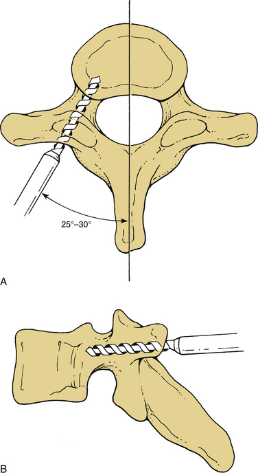
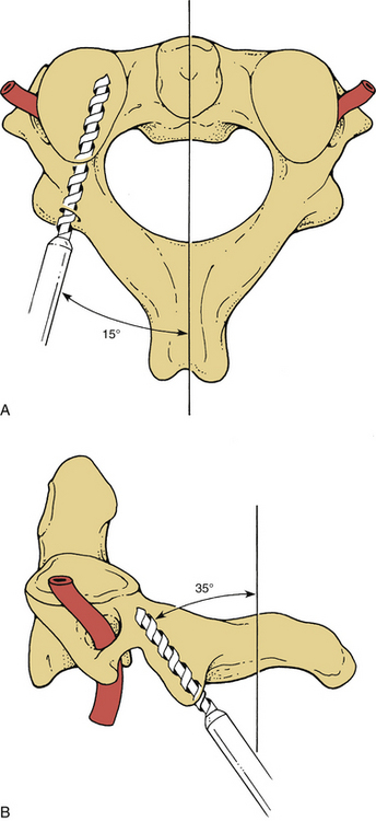
Screw holes are drilled into the lateral masses. Several screw trajectories have been used. Based on anatomic, biomechanical, and clinical observations, we believe the best trajectory begins 1 mm medial to the midportion of the lateral mass and is oriented 15 degrees rostral and 20 to 30 degrees lateral (Fig. 147-4). Although a screw may be placed into C7 by using the angles mentioned, the lateral mass of this vertebra is very small. If C7 lateral mass fixation is desired, it may be more appropriate to drill by using trajectories that are slightly more rostral and lateral. It is often preferable to obtain pedicle fixation at C7 (as well as at T1). The pedicle may be entered 1 mm caudal to the facet joint. Drilling may continue in a directly ventral course, but a trajectory that angles medially 25 to 30 degrees is more consistent with the anatomic position of the pedicle. The orientation is perpendicular to the long axis of the spine at C7, T1, and T226,27 (Fig. 147-5). It is our practice to verify the position of the pedicle by palpation through a small laminoforaminotomy prior to drilling in all cases.
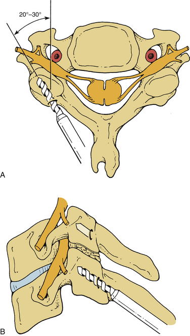
Screws may also be placed into the pars interarticularis of the axis. This technique is more difficult than placing lateral mass screws, and precision is required to avoid vertebral artery injury. The drill entry site is high and medial on the articular mass. The trajectory is as great as 15 degrees from the medial plane and is about 35 degrees from the long axis of the spine6,28 (Fig. 147-6). Fluoroscopy is not necessary for subaxial lateral mass drilling and screw placement, but it should be used when instrumenting the C2 pars.
The dorsal cortex of the lateral mass is perpendicularly pierced with an awl or drill bit to facilitate initial drilling and limit the potential for deviation from the proposed trajectory. One should use a drill bit that incorporates a depth stop, usually at 14 mm. The diameter of the drill bit must comply with the manufacturer’s recommendation for the particular screw to be implanted. Drilling is performed in a precise and steady manner to limit vibration and inadvertent creation of an irregular or oversized hole. Occasionally, the drill bit will be felt to penetrate the ventral cortex before its entire length is used. In this situation, drilling should stop. All of the holes on one side should be drilled and prepared and a plate or rod placed before drilling the opposite side. The screws used for lateral mass fixation are most frequently 3.5 mm in diameter. Cancellous screws provide better purchase than those with cortical threads. The specific screw type used, however, is generally dictated by the system used. If the screw is not self-tapping, at least the dorsal cortex should be tapped before screw insertion. Safe bicortical fixation is usually achieved with 14- to 16-mm screws. Only rarely are longer screws necessary, and shorter screws are appropriate for smaller patients. Although bicortical fixation is considered superior to unicortical fixation, it is not mandatory.28,29 Primary pedicle fixation may be achieved with 4-mm diameter screws.
Inadequate screw purchase may result from osteoporosis, an excessively large hole secondary to inadvertent toggling during drilling, or stripping of threads in the corticocancellous bone during tapping or screw placement. Frequently, in these cases, a “rescue” screw of slightly larger diameter will improve bony purchase.30 These are not placed without risk, however, because they may result in a fracture of the lateral mass. Alternatively, a small amount of polymethylmethacrylate may be placed in the hole before screw tightening. Cervical transfacet screws are an excellent choice for salvaging fixation if a lateral mass screw strips. The purchase achieved by these screws is excellent.31 In selected cases, one may wish to place additional graft material over the dorsal elements after denuding their periosteum and burring the dorsal cortical surface.18 Rods are then contoured and secured using set screws. Excessive force using a rod persuader in securing the screws to the rod should be avoided because the small lateral mass screws may dislodge from the lateral mass if force is applied to reduce the screw to the rod. Additionally, the close proximity to the cervical spinal cord can result in slippage and neurologic injury. Securing the rod is facilitated by the small 3.0- to 3.5-mm titanium rod diameters allowing for some rod flexibility.
Screws are generally polyaxial, allowing for greater freedom in orientation of the bone screw in relation the longitudinal rod. Some screws are “favored-angle screws,” allowing for fewer angulations in certain planes and a bias in the way the screw saddle sits on the screw. Lateral offset connectors can be placed if a screw is significantly outside the rod longitudinal axis, as sometimes occurs with the transition from lateral mass screws to thoracic pedicle screws. Final tightening is often achieved using a torque-limiting screwdriver and antitorque instrument. Sets may also include occipital plates and mechanisms to transition to larger rod diameters used in the thoracic spine. Longer screws are often available for upper thoracic pedicle screw placement as well as for C1 placement. Because lateral mass fixation is successful in almost all patients and has little risk, we do not advocate pedicle fixation from C3 to C6 except in unusual circumstances.32–34
Complication Management
Neurologic Complications
Neurologic complications may be immediate or delayed. The workup of new postoperative neurologic deficits should proceed with great urgency. The possible causes of immediate deficits are numerous. Many instrumentation-related causes of neurologic deficit may be determined radiographically, but the evaluation of these patients must be individualized. Delayed neurologic complications are more likely to be due to instrumentation failures, loss of reduction, or infection. Although evaluation of delayed deficits is dictated by the specific clinical presentation, all such cases should be promptly investigated and appropriate treatment instituted.
Placement of instrumentation may result directly in neurologic compromise. Lateral mass screws have the potential to compress or injure the nerve roots, spinal cord, and vertebral artery. Spinal cord injury secondary to lateral mass screws has not been reported to our knowledge. Anatomic studies support the concept that the spinal cord is not placed at any great risk from lateral mass screw placement. The direction of drill trajectory and screw placement is important for limiting the risk of arterial or root injury. Roy-Camille et al.28 advocate a screw position that begins at the center of the lateral mass, is oriented perpendicular to the long axis of the spine, and is angled 10 degrees laterally. The Magerl technique involves placement of the screw 2 to 3 mm medial and rostral to the center of the lateral mass and a trajectory that runs parallel to the facet joint and is angled 25 degrees laterally.35 Anderson et al.22 suggest screw placement 1 mm medial to the center of the lateral articular mass with trajectory parallel to the facet joints and oriented 10 degrees laterally from the sagittal plane, whereas Cooper et al.23 recommend placement of the screws 1 mm medial to the center of the lateral articular mass and oriented 10 degrees laterally but perpendicular to the long axis of the spine.
Overall, there seems to be a general agreement that the screw trajectory should be at least 10 degrees laterally and oriented no more rostral than the articular surface of the facet joint to minimize the risk of inadvertent injury to the nerve root or vertebral artery.26,36 Cadaveric studies that use such a trajectory suggest that the predicted rates of injury to the nerve roots and vertebral artery would be 3.6% or less and 0%, respectively.36 The actual clinical incidence of nerve root injury secondary to screw placement is much less. In a review of 704 lateral mass screw placements in 79 patients, Heller et al.37 reported a 0.6% rate of nerve root injury. Patients with postoperative radiculopathy secondary to malpositioned screws usually improve significantly with removal of the offending screw.
Spinal Complications
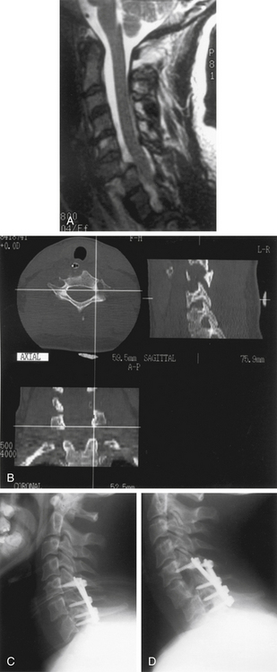
Postoperative spinal instrumentation complications usually, but not always, concern failure to maintain immediate or long-term stability. Poorly conceived stabilization procedures probably account for most dorsal cervical construct failures (Fig. 147-7). When a cervical kyphotic deformity is not adequately reduced, the instrumentation rate failure is increased. Instrumentation should be applied judiciously in osteoporotic patients, and in such individuals a 360-degree approach or postoperative external immobilization is very important. Preoperative evaluation and planning are important to ensure that the proposed construct is biomechanically appropriate for the clinical situation.
Instrumentation failure may occur without clinical consequence.3 Heller et al.37 observed a 1.3% rate of plate breakage over an average follow-up of 1.5 years. In the same review, the following incidences of screw complications were noted: breakage 0.1%, avulsion 0.1%, and loosening 0.9%. Minor instrumentation failures (i.e., 1-mm screw loosening) or those that occur many months after surgery (i.e., single wire breakage) often do not require treatment. Significant or early postoperative instrumentation failures and loss of reduction must be addressed. The management options include institution of rigid external immobilization, bedrest, and/or cervical traction during healing, or reoperation (either repeat dorsal approach or ventral instrumentation). The decision for appropriate treatment must be made on an individual basis, taking into consideration the patient’s condition and prognosis, degree of bony union and instability, and rationale for initial choice of dorsal surgical stabilization.
Summary
Some of the instrumentation systems described in this chapter are currently categorized as class III devices by the United States Food and Drug Administration. Surgeons should be aware of the classification of the instrumentation to be implanted and relay this information to the patient during the preoperative discussion. Most internal fixation devices are classified as temporary devices. Temporary is defined as a device intended to be implanted for more than 30 days but not intended to be implanted permanently. The Orthopedic Surgical Manufacturer’s Association recommends that, whenever possible and practical, bone fixation devices should be removed when their service as an aid to healing is completed; however, the general clinical opinion is that cervical instrumentation that leads to successful fusion without complication does not need to be removed. Each patient should receive preoperative counseling concerning this difference of opinion. When patients understand the risks of repeat surgery yet request removal of hardware after bone fusion has occurred, every attempt should be made to comply with their wishes.
Abumi K., Shono Y., Ito M., et al. Complications of pedicle screw fixation in reconstructive surgery of the cervical spine. Spine (Phila Pa 1976). 2000;25(8):962-969.
An H.S., Gordin R., Renner K. Anatomic considerations for plate-screw fixation of the cervical spine. Spine (Phila Pa 1976). 1991;16:S548-S551.
Heller J.G., Silcox D.H.III, Sutterlin C.E.III. Complications of posterior cervical plating. Spine (Phila Pa 1976). 1995;20:2442-2448.
Maurer P.K., Ellenbogen R.G., Ecklund J., et al. Cervical spondylotic myelopathy: treatment with posterior decompression and Luque rectangle bone fusion. Neurosurgery. 1991;28:680-683.
Mummaneni P.V., Haid R.W., Traynelis V.C., et al. Posterior cervical fixation using a new polyaxial screw and rod system: technique and surgical results. Neurosurg Focus. 2002;12(1):E8.
Traynelis V.C. Anterior and posterior plate stabilization of the cervical spine. Neurosurg Q. 1992;2:59-76.
Wellman B.J., Follett K.A., Traynelis V.C. Complications of posterior articular mass plate fixation of the subaxial cervical spine in 43 consecutive patients. Spine (Phila Pa 1976). 1998;23:193-200.
1. Hadra B.E. Wiring the vertebrae as a means of immobilization in fractures and Pott’s disease. Trans Am Orthop Assoc. 1981;4:206.
2. Abdu W.A., Bohlman H.H. Techniques of subaxial posterior cervical spine fusion: an overview. Orthopaedics. 1992;15:287-295.
3. Traynelis V.C. Anterior and posterior plate stabilization of the cervical spine. Neurosurg Q. 1992;2:59-76.
4. Fehlings M.G., Cooper P.R., Errico T.J. Posterior plates in the management of cervical instability: long-term results in 44 patients. J Neurosurg. 1994;81:341-349.
5. Brodsky A.E., Khalil M.A., Sassard W.R., Newman B.P. Repair of symptomatic pseudarthrosis of anterior cervical fusion. Posterior versus anterior approach. Spine (Phila Pa 1976). 1992;17:1137-1143.
6. Swank M.L., Lowery G.L., Vega J., et al. Salvage reconstruction of failed anterior cervical surgeries. Baltimore, MD: Presented at the 22nd Annual Meeting of the Cervical Spine Research Society; November/December, 1994.
7. Benzel E.C., Hart B.L., Ball P., et al. Fractures of the C-2 vertebral body. J Neurosurg. 1994;81:206-212.
8. Lennarson P.J., Smith D.W., Sawin P.D., et al. Cervical spinal motion during intubation: efficacy of stabilization maneuvers in the setting of complete segmental instability. J Neurosurg. 2001;94(Suppl 2):265-270.
9. Lennarson P.J., Smith D., Todd M.M., et al. Segmental cervical spine motion during orotracheal intubation of the intact and injured spine with and without external stabilization. J Neurosurg. 2000;92(Suppl 2):201-206.
10. Sawin P.D., Todd M.M., Traynelis V.C., et al. Cervical spine motion with direct laryngoscopy and orotracheal intubation: an in vivo cinefluoroscopic study of subjects without cervical abnormality. Anesthesiology. 1996;85:26-36.
11. Sawin P.D., Traynelis V.C., Menezes A.H. A comparative analysis of fusion rates and donor-site morbidity for autogeneic rib and iliac crest bone grafts in posterior cervical fusions. J Neurosurg. 1998;88:255-265.
12. Shaffrey C.I., Spotnitz W.D., Shaffrey M.E., Jane J.A. Neurosurgical applications of fibrin glue: augmentation of dural closure in 134 patients. Neurosurgery. 1990;26:207-210.
13. Maurer P.K., Ellenbogen R.G., Ecklund J., et al. Cervical spondylotic myelopathy: treatment with posterior decompression and Luque rectangle bone fusion. Neurosurgery. 1991;28:680-683.
14. Aldrich E.F., Crow W.N., Weber P.B., Sagnolia T.N. Use of MR imaging-compatible Halifax interlaminar clamps for posterior cervical fusion. J Neurosurg. 1991;74:185-189.
15. Statham P., O’Sullivan M., Russel T. The Halifax clamp for posterior cervical fusion: initial experience in the United Kingdom. Neurosurgery. 1993;32:396-398.
16. Ashman R.B., Herring J.A., Johnston C.E.II, et al. TSRH Universal Spinal Instrumentation. Dallas, TX: Hundley and Associates; 1993.
17. Horgan M.D., Kellog J.X., Chestnut R.M. Posterior cervical arthrodesis and stabilization: an early report using a novel lateral mass screw and rod technique. Neurosurgery. 1999;44:1267-1272.
18. Mummaneni P.V., Haid R.W., Traynelis V.C., et al. Posterior cervical fixation using a new polyaxial screw and rod system: technique and surgical results. Neurosurg Focus. 2002;12(1):E8.
19. Graham A.W., Swank M.L., Kinard R.E., et al. Posterior cervical arthrodesis and stabilization with a lateral mass plate. Clinical and computed tomographic evaluation of lateral mass screw placement and associated complications. Spine (Phila Pa 1976). 1996;21:323-329.
20. Heller J.G., Silcox D.H.III, Sutterlin C.E.III. Complications of posterior cervical plating. Spine (Phila Pa 1976). 1995;20:2442-2448.
21. Wellman B.J., Follett K.A., Traynelis V.C. Complications of posterior articular mass plate fixation of the subaxial cervical spine in 43 consecutive patients. Spine (Phila Pa 1976). 1998;23:193-200.
22. Anderson P.A., Henley M.B., Grady M.S., et al. Posterior cervical arthrodesis with reconstruction plates and bone graft. Spine (Phila Pa 1976). 1991;3:S72-S79.
23. Cooper P.R., Cohen A., Rosiello A., Koslow M. Posterior stabilization of cervical spine fractures and subluxations using plates and screws. Neurosurgery. 1988;23:300-306.
24. Swank M.L., Sutterlin C.E.III, Bossons C.R., et al. Rigid internal fixation with lateral mass plates in multilevel anterior and posterior reconstruction of the cervical spine. Spine (Phila Pa 1976). 1997;22:274-282.
25. Goel V.K., Traynelis V.C., Smith D.W., Scifert J.L. in vitro quasi-static and cyclic biomechanics of a cervical posterior plate vs. facet wiring in a laminectomy model. Anaheim, CA: Presented at the International Mechanical Engineering Congress and Exposition; November, 1998.
26. An H.S., Gordin R., Renner K. Anatomic considerations for plate-screw fixation of the cervical spine. Spine (Phila Pa 1976). 1991;16:S548-S551.
27. Borne G., Bedou G., Pinaudeau M., et al. Treatment of severe lesions of the lower cervical spine (C3-C7). A clinical study and technical considerations in 102 cases. Neurochirurgia (Stuttg). 1988;31:1-13.
28. Roy-Camille R., Saillant G., Mazel C. Internal fixation of the unstable cervical spine by a posterior osteosynthesis with plate and screws. In: Sherk H., Dunn E., Eismont F., et al, editors. The cervical spine. ed 2. Philadelphia: Lippincott-Raven; 1989:390-404.
29. Sutterlin C.E. III: Axis fixation system for posterior cervical reconstruction. In: Hitchon P.W., Rengachary S.S., Traynelis V.C., editors. Spinal fusion and stabilization. New York: Thieme Medical; 1995:159-169.
30. Lovick D.S., Ryken T.C., Traynelis V.C., Dexter F. Assessment of primary and salvage lateral mass screw insertion torque in a cadaveric model. J Spinal Disord. 1997;10:431-435.
31. Klekamp J.W., Ugbo J.L., Heller J.G., Hutton W.C. Cervical transfacet versus lateral mass screws: a biomechanical comparison. J Spinal Disord. 2000;13(6):515-518.
32. Abumi K., Kaneda K. Pedicle screw fixation for nontraumatic lesions of the cervical spine. Spine. 1997;22(16):1853-1863.
33. Abumi K., Kaneda K., Shono Y., Fujiya M. One-stage posterior decompression and reconstruction of the cervical spine by using pedicle screw fixation systems. J Neurosurg. 1999;90(Suppl 1):19-26.
34. Abumi K., Shono Y., Ito M., et al. Complications of pedicle screw fixation in reconstructive surgery of the cervical spine. Spine (Phila Pa 1976). 2000;25(8):962-969.
35. Jeanneret B., Magerl F., Ward E.H., Ward J. Posterior stabilization of the cervical spine with hook plates. Spine (Phila Pa 1976). 1991;16:S56-S63.
36. Heller J.G., Carlson G.D., Abitbol J.-J., Garfin S.R. Anatomic comparison of the Roy-Camille and Magerl techniques for screw placement in the lower cervical spine. Spine (Phila Pa 1976). 1991;16:S552-S557.
37. Heller J.G., Silcox H., Sutterlin C.III. Complications of posterior cervical plating. Baltimore, MD: Presented at the 22nd Annual Meeting of the Cervical Spine Research Society; November/December, 1994.
[/level-membership-for-neurosurgery-category][not-level-membership-for-neurosurgery-category]
Chapter 147 Dorsal Subaxial Cervical Instrumentation Techniques
Subaxial cervical instability has many causes, including trauma, degenerative disease, neoplasm, and infection. Instability may also develop after spinal canal or foraminal decompression or in conjunction with tumor resection. Historically, the management of such instability first consisted of extended immobilization with traction or an orthosis to maintain proper alignment until bony and/or ligamentous healing transpired. Despite the usefulness of these treatment modalities, they predispose patients to a variety of medical complications. Furthermore, such management does not always result in long-term spinal stability. In 1891, Hadra1 described the role of spinous process wiring to treat traumatic and inflammatory cervical instability. Subsequently a multitude of cervical fusion techniques were reported that used wires secured to the spinous processes, laminae, and/or facets. Cervical wiring techniques are important in the management of cervical instability.
Indications for Surgery
Trauma
Trauma is a common indication for dorsal cervical stabilization.2 The primary management of cervical spine injuries consists of realignment (when necessary), decompression of the neural elements (when indicated), and stabilization. In the setting of trauma, if the spine is in good alignment and no decompression is necessary, external immobilization may be all that is required to protect the neural elements while healing occurs. This is particularly true when the major cause of the instability is bony injury. Primary ligamentous instability is much less likely to resolve after immobilization; hence early surgical stabilization is often an appropriate consideration in the management of these injuries.
Instrumentation of the dorsal cervical spine should be considered seriously in all trauma victims who require an open reduction or a dorsal cervical decompression. Persistent dorsal ligamentous instability is most appropriately treated by dorsal surgical stabilization; in fact, it is not unreasonable to offer patients with severe ligamentous injuries internal fixation as an alternative to halo immobilization. Fixation across the afflicted level only is usually successful in achieving long-term stabilization in patients with dorsal ligamentous injuries; however, consideration should be given toward incorporating additional levels into the construct in the setting of severe instability3 (Fig. 147-1). Bony cervical spinal injuries may also be stabilized by using dorsal instrumentation. In particular, cervical lateral mass instrumentation may be used in the presence of laminar and spinous process fractures that often preclude the use of many other types of dorsal fixation.
Extension instability and injuries of the ventral axial spine have been managed successfully by using multilevel dorsal fixation; however, a ventral approach is usually more appropriate. This is particularly true if the spinal canal is compromised from bone or disc fragments or when a burst fracture is associated with 25-degree or greater kyphosis.3,4
Spondylosis
Dorsal cervical instrumentation is also useful in the management of spondylotic disease. Proper instrumentation at the time of initial decompression in patients with abnormal segmental motion or absent lordosis markedly decreases their risk of developing postlaminectomy kyphosis. In these cases, instrumentation and subsequent fusion are important to prevent further problems; when a kyphotic deformity has occurred, treatment with dorsal instrumentation alone does not usually provide the optimum result. Almost invariably, ventral spinal reconstruction is the necessary first step needed to correct or halt progressive postlaminectomy kyphotic deformities; dorsal fixation may then be considered as an adjunctive measure in select patients. Dorsal fusion may provide a more successful means of treating patients who experience symptoms from failed ventral arthrodesis than a second ventral surgery.5,6 In highly selected cases of severe ventral and dorsal spinal incompetence, a combined or staged “360-degree” operation may be indicated.
General Considerations
Imaging
CT provides better bony detail than MRI and therefore is more useful to define fractures. MRI often complements CT in the trauma setting because of its ability to define ligamentous injury.7 Both modalities are useful in assessing the extent of tumor involvement in patients with metastatic malignancies. CT myelograms should be considered in patients who are unable to have MRIs or when the MRI is equivocal, such as when a previous instrumentation artifact obscures adequate visualization. CT allows for evaluation of the transverse foramina and, by proxy, the vertebral artery. Localization of the vertebral artery is important in surgical planning for placement of screws in the cervical spine.
Intraoperative Monitoring
Neurophysiologic monitoring can be used to monitor the spinal cord integrity during surgery. Options include monitoring somatosensory-evoked potentials (SSEPs) and motor-evoked potentials (MEPs). SSEPs represent signal-averaged data often over several minutes and monitor the spinal cord dorsal columns. MEPs are usually associated with patient motion during recording and are therefore obtained episodically. Special anesthesia considerations exist with intraoperative monitoring. The usefulness of intraoperative monitoring is established for intradural tumors and vascular malformations but is unclear for other cervical spine surgeries. The authors rarely employ such monitoring (barring experimental protocols) in treating cervical pathology other than intrinsic tumors, vascular malformations, or severe deformities.
Tracheal Intubation
Awake fiberoptic intubations should be considered in patients with significant preoperative instability. Fiberoptic intubation allows for securing the airway with minimal manipulation and extension of the cervical spine. Awake intubation facilitates awake positioning of the patient. Careful intubation under general anesthesia is an alternative to an awake intubation. The head must be held in the neutral position or traction employed if there is a concern for preoperative instability. External orthoses, manual in-line immobilization, and/or axial traction may be used to limit the motion of unstable segments during intubation and positioning.8–10
Bony Fusion
Corticocancellous bone may be obtained from the cervical laminae if a laminectomy is performed. If spinal canal decompression is not warranted, adequate bone for a facet fusion may be obtained from the cervical or upper thoracic spinous processes. Another alternative is to harvest bone from the dorsal iliac crest or a rib.11 Corticocancellous bone is placed over the dorsal elements.
Cerebrospinal Fluid Leak
If cerebrospinal fluid (CSF) is noted at any time during the procedure, the site of the leak should be determined. Ideally, all dural defects are closed primarily. If a dural violation cannot be directly repaired, such as may be the case if the defect is located laterally or ventrally, fibrin glue may help seal the leak.12 If a watertight dural closure is not achieved, wound drains should be avoided. In some situations, lumbar CSF drainage will help decrease the risk of developing a CSF fistula or a pseudomeningocele.
Wound Closure
The wound should be closed in layers with interrupted suture. Removal of the dorsal portion of a prominent C7 and/or T1 spinous process can be extremely helpful for limiting wound tension in slender patients. If local irradiation has been performed or is anticipated, nonabsorbable suture should be considered, at least for the fascial closure. It may be wise to close the entire wound with such suture in these patients. Wound drain placement should be individualized. Some completely dry wounds need no drain; however, if there is oozing from the raw bone surfaces, it may be prudent to place a drain. This is particularly important if a laminectomy has been performed. All wound drains should be tunneled and exit via a separate stab incision.
Dorsal Subaxial Cervical Instrumentation Techniques
Luque Instrumentation
Stainless steel pediatric Luque L-rods and Luque rectangles (Zimmer, Warsaw, IN) may be used to stabilize the cervical spine.13 The rectangular construct provides greater torsional stability than the L-rods and is therefore preferable. These devices are not indicated for one- or two-level fixation but rather multilevel stabilization procedures. Ideally, both the rods and the rectangles are segmentally secured to every level traversed; however, this is not always necessary. Luque instrumentation can be used to bridge dorsal element defects, such as may occur with metastatic malignancies; however, when using this technique, at least two levels of segmental fixation must be obtained above and below the incompetent region. These devices are most useful for fixation extending to the upper cervical spine or crossing the cervicothoracic junction.
[/not-level-membership-for-neurosurgery-category]
