[level-membership-for-orthopaedics-category]
CHAPTER 7 Distal Radius Fractures Treated with the CPX System
There are many ways to treat distal radius fractures. Over the years, many techniques and instruments have evolved in this frequently changing landscape. The basic principles of fracture treatment, however—fracture reduction, restoration of joint congruency, maintenance of reduction throughout healing, early mobilization, and the resumption of activities of daily living—remain the same.1
This ubiquitous fracture has become very important to our aging population. Life expectancy has increased dramatically, and people are more active as they age.2,3 A cavalier attitude in treating these fractures can lead to unhappy patients who are unwilling to accept either the deformity or the functional compromise of such injuries despite their age.
Deforming angular, compressive, and torsional forces affect fractures of the distal radius.4,5 Such forces are generated by musculotendinous units, gravity, and patient activity, and can lead to collapse of the fracture, especially in elderly patients with osteoporotic bone.2,3 This collapse occurs in four radiological dimensions—radial height, radial inclination, palmar tilt, and ulnar variance—resulting in deformity and functional loss to the patient.5–8
To counteract these deforming forces, many forms of immobilization are used. The traditional method of cast immobilization still has a place in the treatment of distal radius fractures.6–10 In unstable intra-articular fractures, the treatment becomes challenging. Casting alone or in combination with the application of percutaneous Kirschner wires (K-wires), pins in plaster, or external fixators has not solved the problems associated with these fractures.7,11–13 Although dorsal plating and, more recently, volar plating techniques provide stable fixation, they require extensive soft tissue dissection.14–19
Biomechanical Concepts of Internal Fixation
A review of the literature provides an understanding of the basic biomechanical principles of internal fixation applied to distal radius fractures. A single wire (pin) through a fracture fragment allows rotation and translation along the axis of the wire.4,20,21 A second wire through the fragment provides stability between the two fragments as long as the second wire is not parallel to the first.4,21,22 If the second wire is parallel to the first, the fragment can still translate along the pin axis; complete stability is not insured.4 In an experimental cadaver model, Graham and Louis found that as the number of pins was increased from one to four, the construct became more stable.20 In this model, the pins that crossed each other at different angles through the ulnar shaft provided the greatest stability.
Rogge and colleagues,4 in a three-dimensional finite element model, showed that two pins traversing the fracture, as in cross-pinning, are more stable than two parallel pins. Naidu and coworkers23 reported similar findings. Crossed K-wires capture the larger fragments and buttress the smaller fragments, preventing gross articular collapse. In the wrist, where loads of 100 to 180 lb are anticipated in the postoperative phase, it is beneficial to distribute the load over multiple crossed K-wires in the Kapandji fashion.24,25 This configuration also allows the surgeon to decrease the diameter of the pins significantly, from 3.5 to 1.6 mm.
Cross pin fixation has been in use for a long time.26 Cross pin fixation alone does not hold an unstable distal radius fracture, however, unless another means of further support is provided, either by a cast or an external fixator.26,27 The application of a cast or a bridging external fixator carries specific inherent problems that are well known within the orthopaedic community.28–34 The CPX system was conceived as a hybrid of cross pin fixation and a nonbridging external fixator. The nonbridging external fixator provides stability to the cross pin construct, holding reduction of the distal radius fracture without compromising wrist mobilization.
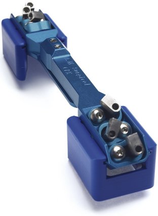
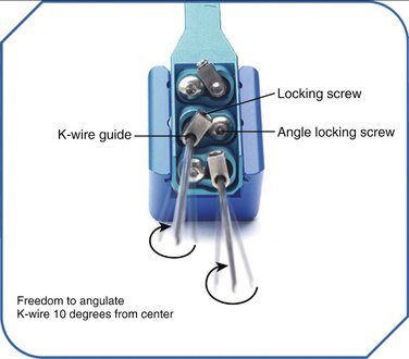
The CPX system is a minimally invasive technique using closed reduction and internal fixation with percutaneous cross pin fixation and a nonbridging external fixator. The CPX device consists of an adjustable two-part aluminum sliding bar (11.5 to 14.5 cm) (Fig. 7-1). Two screws adjust the length of the bar, and at each end of the bar there is a head with three adjustable K-wire fixators. Each K-wire fixator has a guide hole, allowing freedom to angle the K-wire 10 degrees from center, and two screws, one to control the angle of the K-wire insertion and the other to lock the K-wire to the fixator (Fig. 7-2). The CPX system is indicated for treatment of displaced reducible extra-articular and nondisplaced and displaced reducible intra-articular distal radius fractures.
CPX System
Biomechanics of CPX System
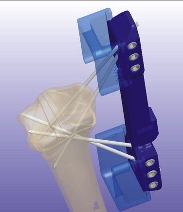
To achieve successful outcomes, it is important to understand how this system works biomechanically and how it differs from other systems available today. It has been shown that the stability of the fixation with K-wires is greatly enhanced by increasing the number of K-wires.20 As noted, ensuring that these wires are not parallel to each other provides three-dimensional stability.21 To minimize motion of the fragments and prevent articular step-off or deformity, it is important to achieve multiplanar (three-dimensional) stability of all major fragments (Fig. 7-3).7 The CPX system, with a minimum of four wires (two distally and two proximally) crossing each other at different angles, greatly enhances the stability of the construct.
In traditional bridging and nonbridging external fixators, the pins are perpendicular to the long axis of the bone. This configuration unloads the fracture.5 Comparatively, the pins of the CPX system are more longitudinally oriented and do not unload the fracture (Fig. 7-4). Wires with small diameters (1.6 mm), which flex when the construct is loaded and allow load sharing across the fracture fragments, facilitate callus formation27 and reduce the risk of nonunion because of stress shielding. Also, the cross positioning of K-wires fixes the larger fracture fragments while buttressing the smaller fragments, helping to maintain joint congruency (see Figs. 7-3 and 4).
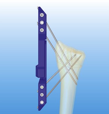
The cross pin configuration works similar to reinforced concrete (i.e., the pin is similar to steel, and the bone is similar to cement), and the external device acts like a pillar giving rigidity to the whole system (resisting compressive, torsional, and angular forces) (see Fig. 7-4). Among external fixators, bilateral and three-dimensional frames give more stability because of their multiplanar configuration compared with unilateral frames.34,35 Conversely, the CPX system is lightweight (41 g, with the pins), and despite its unilateral frame, achieves three-dimensional stability because of its multiplanar K-wire configuration (see Fig. 7-3).
Indications and Contraindications
Using AO classification, the CPX system is indicated for extra-articular A2 and A3 fractures; simple articular B1 fractures; nondisplaced or reducible and minimally displaced three-part fractures; and C1 and comminuted C2.1, C2.2, and C3.1 fractures. Although, I have successfully treated dorsal shear B2.2 and volar shear B3.3 fractures (see Illustrated Cases later), further investigation and clinical studies are needed to recommend these fractures and C2.3, C3.2, and C3.3 fractures further as indications for the CPX system. Osteoporosis and an unstable distal radioulnar joint are not contraindications. A small distal fragment (<1 cm) is not an absolute contraindication, as long as it is reducible and stable. This system is not recommended for patients with massive swelling, an unstable soft tissue envelope, open fractures, dementia, or advanced Parkinson’s disease, or for patients who are not willing to commit to the postoperative protocol.
Surgical Technique
The fracture is reduced by using the classic maneuver, palmar flexion and ulnar deviation.36 If this maneuver fails, finger trap traction can be used. Finger traps are applied to the thumb and index finger and sometimes to the middle finger, with 10 lb of traction or more, if needed. If greater radial inclination is desired, only the thumb is placed in a finger trap. The only drawback to longitudinal traction is that palmar tilt is not restored.37 This problem can be overcome by applying dorsal pressure to the distal fragment, pushing in the volar direction to maintain palmar tilt until the first K-wire is in place.
After reduction, it is important to FluoroScan and assess the fracture in the anteroposterior, lateral, and oblique planes for restoration of radial inclination, radial height, palmar tilt, ulnar variance, and articular joint congruency. The tissue protector is placed against the radial styloid between the first and second dorsal compartment, and FluoroScan is done to determine placement of the first K-wire (Fig. 7-5A). The tissue protector is removed, and a small stab wound is made in its place (Fig. 7-5B). Through the stab wound, a clamp is introduced, and the soft tissues are spread through to the bone (Fig. 7-5C).
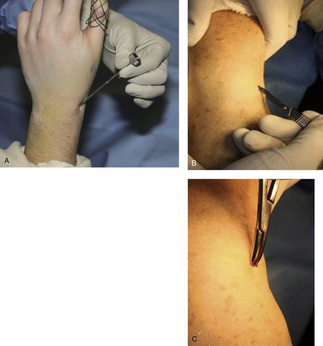
FIGURE 7-5 A, Placement of the tissue protector against the radial styloid to determine with FluoroScan placement of the first K-wire. B, Stab wound. C, Insertion of clamp into stab wound.
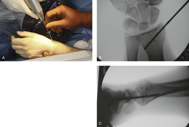
A 1.6-mm K-wire is driven freehand at a 40- to 45-degree angle through the tissue protector into the bone (Fig. 7-6A). The aim is to cross the fracture site and come out on the opposite side proximally in the mid lateral plane, penetrating the ulnar cortex (Fig. 7-6B). This can be very easily assessed under FluoroScan by imaging a lateral view and making sure that the K-wire is not too dorsal or too volar; otherwise, the K-wire may snag either the extensor or the flexor tendon (Fig. 7-6C). After satisfactorily driving the first pin, the fracture is stable enough so that one does not have to continue the dorsal pressure on the distal fragment to maintain the palmar tilt. The radial inclination and radial height continue to be maintained by the traction.
Before applying the CPX device, it is important to loosen all of the screws. The device is provided with two blue plastic spacers; these are used to ensure that the device is a certain distance away from the skin, allowing for mobilization of the wrist (see Fig. 7-1). With the spacers attached to the device, one slides the device over the K-wire through the distalmost guide hole. The length of the fixator can be adjusted to accommodate for the insertion of the proximal K-wire.
I find it helpful at this point to take a K-wire and place it on the dorsal aspect of the skin, and FluoroScan in the anteroposterior plane showing that the K-wire is aimed at the lunate fossa. I draw a line along the K-wire with a marking pen (Fig. 7-7). Using this line as a guide, make the proximal stab wound in the mid lateral plane on the radial side approximately 1 to 2 cm distal to the line drawn, introduce the clamp and spread the tissue down to the bone. Subsequently, slide the proximal head of the CPX fixator to the desired length, slide the tissue protector through the proximal-most K-wire guide hole, into the stab wound, ensuring that there are no intervening soft tissues.
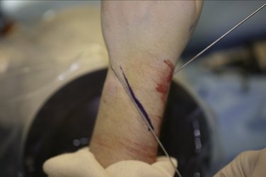
FIGURE 7-7 Marking Pen Guide Line Ensuring Alignment of the K-wire to the Lunate Fossa with Fluoroscan.
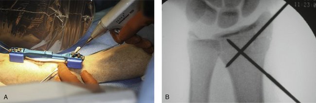
Next, a 1.6-mm K-wire is passed through the tissue protector and driven into the bone at an angle that aims at the lunate fossa (Fig. 7-8A). One verifies that the wire is aiming toward the lunate fossa by checking the anteroposterior view on the fluoroscan; one proceeds only if satisfied with its position. Otherwise, the K-wire is removed, the angle of the tissue protector is changed, and the K-wire is reinserted until one satisfactorily aims the wire at the lunate fossa (Fig. 7-8B). One of the most important things to remember is that the cortical bone is difficult to penetrate proximally; take your time and continue driving the K-wire until it penetrates the cortex.
Next, working from a proximal to distal direction, one makes another stab wound and, using the tissue protector to limit soft tissue damage, drives the third K-wire toward the lunate fossa. After this is accomplished, one drives the fourth K-wire from distal to proximal, again using a tissue protector so as not to damage the radial nerve. I prefer two pins proximally and two pins distally, which should suffice in most cases (Fig. 7-9). One might consider using a third K-wire proximally or distally. FluoroScan x-rays should be taken in the anteroposterior and lateral planes to ensure the pin alignment. One tightens the screws to affix the additional K-wires to the device, then checks each screw one by one and tightens if indicated.
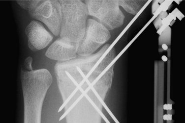
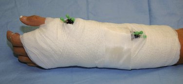
The pins are cut at a convenient level, and pin caps are placed on the cut ends for protection. The traction is then removed, and FluoroScan views are taken to ascertain that there is no loss of reduction. Bupivacaine (Marcaine) with epinephrine is injected around the pins proximally and distally and into the fracture hematoma. This medication makes the patient comfortable postoperatively. Xeroform dressings are applied around the pins followed by a soft dressing and a wrist/forearm volar splint (Fig. 7-10). The patient is sent home with instructions to move the fingers through their entire range of motion and to keep the arm elevated.
Postoperative Study Protocol
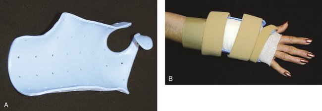
The patient is seen in the office 3 to 5 days postoperatively for evaluation and referral to an occupational therapist. During this visit, a custom removable orthosis is applied (Fig. 7-11), and the patient is instructed to begin a formal home exercise program for the wrist and fingers.
Author’s Experience
Cross pin fixation with a plaster bar strut, an experimental precursor to the CPX system, was used to treat 14 distal radius fractures between September 2001 and February 2004. Between September 2004 and July 2007, 45 patients, 29 women and 15 men, with 48 distal radius fractures, were treated with the CPX system. The average age was 55 years (range 17 to 87 years).
Results
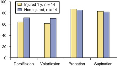
Initial occupational therapy evaluation (6 to 10 days post surgery) revealed that the patients’ mean wrist range of motion of the operative wrist was as follows: dorsiflexion 22 degrees (range −20 to 52 degrees), volar flexion 23 degrees (range 9 to 50 degrees), pronation 64 degrees (range −14 to 86 degrees), and supination 25 degrees (range −3 to 87 degrees). Range of motion continued to progress throughout recovery. Figure 7-12 shows assisted range of motion relative to the uninjured hand/wrist at 1 year.
Illustrated Cases
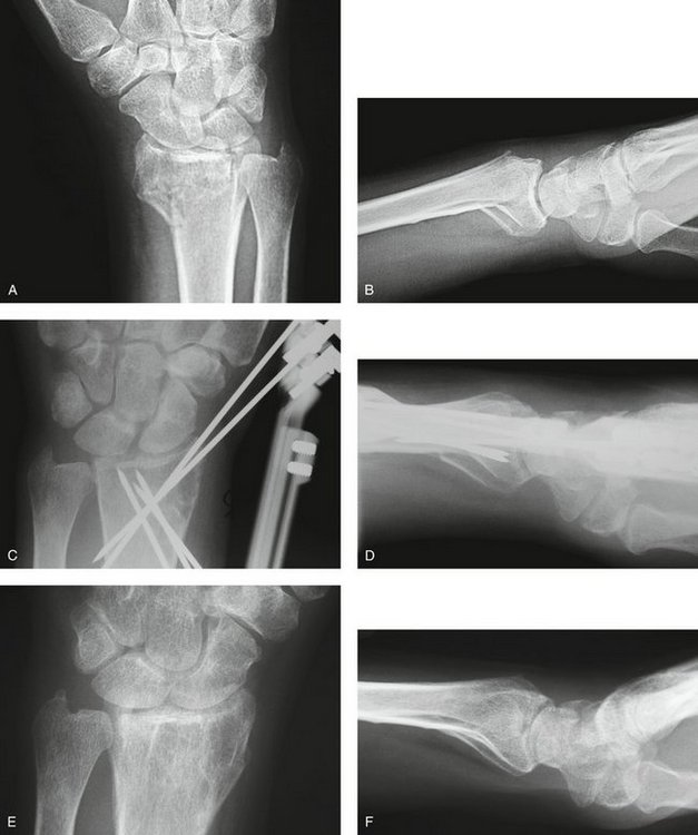
Three cases are illustrated with preoperative, postoperative, and healed anteroposterior and lateral radiographic views in addition to range of motion, DASH, and PRWHE scores from the patient’s most recent follow-up visit. Figure 7-13 shows a 17-year-old boy with a left nondominant C2.2 fracture. At 8 weeks post surgery, dorsiflexion was 76 degrees, volar flexion was 76 degrees, pronation was 90 degrees, supination was 90 degrees, DASH score was 16.67, and PRWHE was 10. Figure 7-14 shows a 48-year-old woman with osteoporosis and a left nondominant C1.2 distal radius fracture. At 6 months post surgery, dorsiflexion was 76 degrees, volar flexion was 66 degrees, pronation was 88 degrees, supination was 88 degrees, DASH score was 11.66, and PRWHE was 17. Figure 7-15 shows a 55-year-old woman with a B3.3 volar Barton distal radius fracture of the right dominant hand. At 1 year post surgery, dorsiflexion was 60 degrees, volar flexion was 50 degrees, pronation was 82 degrees, supination was 77 degrees, DASH score was 9.48, and PRWHE was 17. A CT scan view of the B3.3 volar Barton fracture is shown in Figure 7-16.
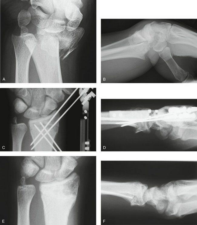
FIGURE 7-13 A 17-Year-Old Boy with a C2.2 Distal Radius Fracture and Major Extra-articular Element Treated with the CPX System. Preoperative views—posteroanterior (A) and lateral (B). Postoperative views—posteroanterior (C) and lateral (D). Views after healing—posteroanterior (E) and lateral (F).
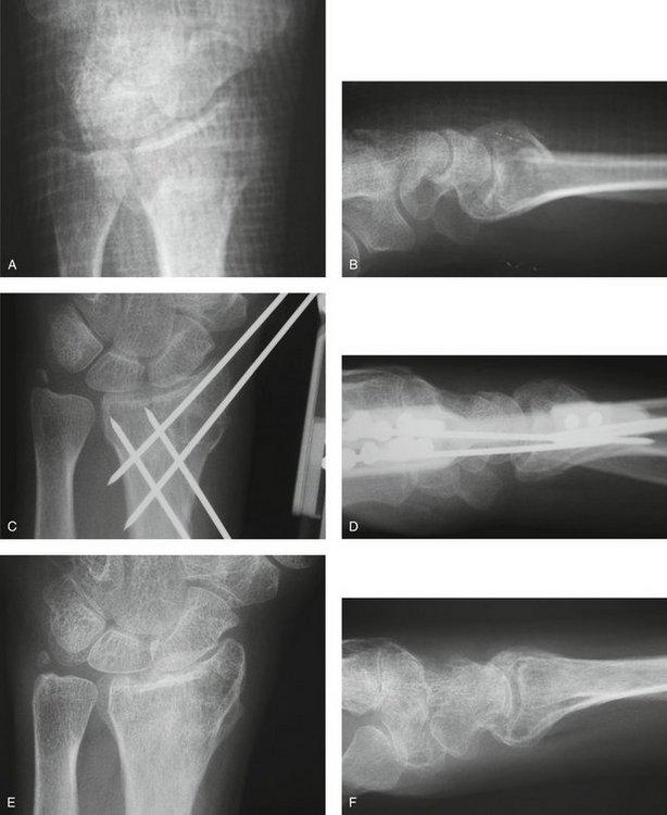
FIGURE 7-14 A 48-Year-Old Woman with Osteoporosis and a C1.2 Distal Radius Fracture Treated with the CPX System. Preoperative views—posteroanterior (A) and lateral (B). Postoperative views—posteroanterior (C) and lateral (D). E and F, View after healing—posteroanterior.

1. Krishnan J, Chipcase S, Slavotinek J. Intraarticular fractures of the distal radius treated with metaphyseal external fixation. J Hand Surg [Br]. 1998;23:396-399.
2. Mallmin H, Ljunghall S. Distal radius fracture is an early sign of general osteoporosis: bone mass measurements in a population based study. Osteopor Int. 1994;4:357-361.
3. Gausepohl T, Worner S, Pennig D, et al. Extraarticular external fixation in distal radius fractures pin placement in osteoporotic bone. Injury. 2001;32:79-85.
4. Rogge R, Adams B, Goel VK. An analysis of bone stresses and fixation stability using a finite element model of simulated distal radius fractures. J Hand Surg [Am]. 2002;27:86-92.
5. Bindra RR. Biomechanics and biology of external fixation of distal radius fractures. Hand Clin. 2005;21:363-373.
6. Nesbitt KS, Faille JM, Les C. Assessment of instability factors in adult distal radius fractures. J Hand Surg [Am]. 2004;29:1128-1138.
7. Gradl G, Jupiter JB, Gierer P, et al. Fractures of the distal radius treated with a nonbridging external fixation technique using multiplanar K-wires. J Hand Surg [Am]. 2005;30:960-968.
8. Slutsky DJ, Herman M. Rehabilitation of distal radius fractures: a biomechanical guide. Hand Clin. 2005;21:455-468.
9. Rogachefsky RA, Lipson SR, Applegate B, et al. Treatment of severely comminuted intra-articular fractures of the distal end of the radius by open reduction and combined internal and external fixation. J Bone Joint Surg Am. 2001;83:509-519.
10. Hanel DP, Jones MD, Trumble TE. Wrist fractures. Orthop Clin North Am. 2002;33:35-37.
11. Agee JM. Distal radius fractures: multiplanar ligamentotaxis. Hand Clin. 1993;9:577-585.
12. Kapoor H, Agarwal A, Dhaon BK. Displaced intra-articular fractures of distal radius: a comparative evaluation of results following closed reduction, external fixation. Injury. 2000;31:75-79.
13. Wolf J, Weil W, Hanel D, et al. A biomechanic comparison of an internal radiocarpal-spanning 2.4-mm locking plate and external fixation in a model of distal radius fractures. J Hand Surg [Am]. 1999;24:516-524.
14. Rozental TD, Blazar PE. Functional outcome and complications after volar plating for dorsally displaced, unstable fractures of the distal radius. J Hand Surg [Am]. 2006;31:359-365.
15. Smith DW, Henry MH. Volar fixed-angle plating of the distal radius. J Am Acad Orthop Surg. 2005;13:28-36.
16. Ruch DS, Papadonikolakis A. Volar versus dorsal plating in the management of intra-articular distal radius fractures. J Hand Surg [Am]. 2006;31:9-16.
17. Harness NG, Meals RA. The history of fracture fixation of the hand and wrist. Clin Orthop. 2006;445:19-29.
18. Ruch DS, Yang C, Patersen Smith B. Result of palmar plating of the lunate facet combined with external fixation for the treatment of high-energy compression fractures of the distal radius. J Orthop Trauma. 2004;18:28-33.
19. Rush LV. Closed medullary pinning of Colles’ fracture. Clin Orthop. 1954;3:152-162.
20. Graham TJ, Louis DS. Biomechanical aspects of percutaneous pinning for distal radius fractures. In: Saffar P, Cooney W, editors. Fractures of the Distal Radius. London: Martin Dunitz, 1995.
21. Heatherly RD, Adams BD, Goel VK: An evaluation of distal radius fracture pinning techniques using experimentally validated FE model. Summer Bioengineering conference, ASMEM, Big Sky, Montana, 1999.
22. Stein AHJr, Katz SF. Stabilization of comminuted fractures of the distal inch of the radius: percutaneous pinning. Clin Orthop. 1975;108:174-181.
23. Naidu SH, Capo JT, Moulton M, et al. Percutaneous pinning of distal radius fractures: a biomechanical study. J Hand Surg [Am]. 1997;22:252-257.
24. Ruschel PH, Albertoni WM. Treatment of unstable extra-articular distal radius fractures by modified intrafocal Kapandji method. Tech Hand Up Extrem Surg. 2005;9:7-16.
25. Weil WM, Trumble TE. Treatment of distal radius fractures with intrafocal (Kapandji) pinning and supplemental skeletal stabilization. Hand Clin. 2005;21:317-328.
26. Clancey GJ. Percutaneous Kirschner-wire fixation of Colles’ fractures: a prospective study of thirty cases. J Bone Joint Surg [Am]. 1984;66:1008-1014.
27. Wolfe SW, Austin G, Lorenze M, et al. A biomechanical comparison of different wrist external fixators with and without K-wire augmentation. J Hand Surg [Am]. 1999;24:516-524.
28. Gutow AP. Avoidance and treatment of complication of distal radius fractures. Hand Clin. 2005;21:295-305.
29. Anderson JT, Lucas GL, Buhr BR. Complications of treating distal radius fractures with external fixation: a community experience. Iowa Orthop J. 2004;24:53-59.
30. Weber SC, Szabo RM. Severely comminuted distal radius fractures as an unsolved problem: complications associated with external fixation and pin and plaster techniques. J Hand Surg [Am]. 1986;11:156.
31. Sanders RA, Keppel FL, Waldrop JI. External fixation of distal radial fractures: results and complications. J Hand Surg [Am]. 1991;16:385-391.
32. Moroni A, Vannini F, Mosca M, et al. State of the art review: techniques to avoid pin loosening and infection in external fixation. J Orthop Trauma. 2002;16:189-195.
33. Parameswara AD, Roberts CS, Seligson D, et al. Pin tract infection with contemporary external fixation: how much of a problem? J Orthop Trauma. 2003;17:503-507.
34. Davenport WC, Miller G, Wright TW. Wrist ligament strain during external fixation: a cadaveric study. J Hand Surg [Am]. 1999;24:102-107.
35. Lindsay CS, Richards RS, King GJ, et al. Ilizarov hybrid external fixation for fractures of the distal radius, part I: feasibility of transfixion wire placement. J Hand Surg [Am]. 2001;26:210-217.
36. Fernandez DL, Jupiter JB. Fractures of the Distal Radius: A Practical Approach to Management, 2nd ed. New York: Springer; 2003.
37. Bartosh RA, Saldana MJ. Intraarticular fractures of the distal radius: a cadaveric study to determine if ligamentotaxis restores radiopalmar tilt. J Hand Surg [Am]. 1990;15:18-21.
[/level-membership-for-orthopaedics-category][not-level-membership-for-orthopaedics-category]
CHAPTER 7 Distal Radius Fractures Treated with the CPX System
There are many ways to treat distal radius fractures. Over the years, many techniques and instruments have evolved in this frequently changing landscape. The basic principles of fracture treatment, however—fracture reduction, restoration of joint congruency, maintenance of reduction throughout healing, early mobilization, and the resumption of activities of daily living—remain the same.1
This ubiquitous fracture has become very important to our aging population. Life expectancy has increased dramatically, and people are more active as they age.2,3 A cavalier attitude in treating these fractures can lead to unhappy patients who are unwilling to accept either the deformity or the functional compromise of such injuries despite their age.
Deforming angular, compressive, and torsional forces affect fractures of the distal radius.4,5 Such forces are generated by musculotendinous units, gravity, and patient activity, and can lead to collapse of the fracture, especially in elderly patients with osteoporotic bone.2,3 This collapse occurs in four radiological dimensions—radial height, radial inclination, palmar tilt, and ulnar variance—resulting in deformity and functional loss to the patient.5–8
To counteract these deforming forces, many forms of immobilization are used. The traditional method of cast immobilization still has a place in the treatment of distal radius fractures.6–10 In unstable intra-articular fractures, the treatment becomes challenging. Casting alone or in combination with the application of percutaneous Kirschner wires (K-wires), pins in plaster, or external fixators has not solved the problems associated with these fractures.7,11–13 Although dorsal plating and, more recently, volar plating techniques provide stable fixation, they require extensive soft tissue dissection.14–19
Biomechanical Concepts of Internal Fixation
A review of the literature provides an understanding of the basic biomechanical principles of internal fixation applied to distal radius fractures. A single wire (pin) through a fracture fragment allows rotation and translation along the axis of the wire.4,20,21 A second wire through the fragment provides stability between the two fragments as long as the second wire is not parallel to the first.4,21,22 If the second wire is parallel to the first, the fragment can still translate along the pin axis; complete stability is not insured.4 In an experimental cadaver model, Graham and Louis found that as the number of pins was increased from one to four, the construct became more stable.20 In this model, the pins that crossed each other at different angles through the ulnar shaft provided the greatest stability.
Rogge and colleagues,4 in a three-dimensional finite element model, showed that two pins traversing the fracture, as in cross-pinning, are more stable than two parallel pins. Naidu and coworkers23 reported similar findings. Crossed K-wires capture the larger fragments and buttress the smaller fragments, preventing gross articular collapse. In the wrist, where loads of 100 to 180 lb are anticipated in the postoperative phase, it is beneficial to distribute the load over multiple crossed K-wires in the Kapandji fashion.24,25 This configuration also allows the surgeon to decrease the diameter of the pins significantly, from 3.5 to 1.6 mm.
Cross pin fixation has been in use for a long time.26 Cross pin fixation alone does not hold an unstable distal radius fracture, however, unless another means of further support is provided, either by a cast or an external fixator.26,27 The application of a cast or a bridging external fixator carries specific inherent problems that are well known within the orthopaedic community.28–34 The CPX system was conceived as a hybrid of cross pin fixation and a nonbridging external fixator. The nonbridging external fixator provides stability to the cross pin construct, holding reduction of the distal radius fracture without compromising wrist mobilization.
The CPX system is a minimally invasive technique using closed reduction and internal fixation with percutaneous cross pin fixation and a nonbridging external fixator. The CPX device consists of an adjustable two-part aluminum sliding bar (11.5 to 14.5 cm) (Fig. 7-1). Two screws adjust the length of the bar, and at each end of the bar there is a head with three adjustable K-wire fixators. Each K-wire fixator has a guide hole, allowing freedom to angle the K-wire 10 degrees from center, and two screws, one to control the angle of the K-wire insertion and the other to lock the K-wire to the fixator (Fig. 7-2). The CPX system is indicated for treatment of displaced reducible extra-articular and nondisplaced and displaced reducible intra-articular distal radius fractures.
CPX System
Biomechanics of CPX System
To achieve successful outcomes, it is important to understand how this system works biomechanically and how it differs from other systems available today. It has been shown that the stability of the fixation with K-wires is greatly enhanced by increasing the number of K-wires.20 As noted, ensuring that these wires are not parallel to each other provides three-dimensional stability.21 To minimize motion of the fragments and prevent articular step-off or deformity, it is important to achieve multiplanar (three-dimensional) stability of all major fragments (Fig. 7-3).7 The CPX system, with a minimum of four wires (two distally and two proximally) crossing each other at different angles, greatly enhances the stability of the construct.
In traditional bridging and nonbridging external fixators, the pins are perpendicular to the long axis of the bone. This configuration unloads the fracture.5 Comparatively, the pins of the CPX system are more longitudinally oriented and do not unload the fracture (Fig. 7-4). Wires with small diameters (1.6 mm), which flex when the construct is loaded and allow load sharing across the fracture fragments, facilitate callus formation27 and reduce the risk of nonunion because of stress shielding. Also, the cross positioning of K-wires fixes the larger fracture fragments while buttressing the smaller fragments, helping to maintain joint congruency (see Figs. 7-3 and 4).
The cross pin configuration works similar to reinforced concrete (i.e., the pin is similar to steel, and the bone is similar to cement), and the external device acts like a pillar giving rigidity to the whole system (resisting compressive, torsional, and angular forces) (see Fig. 7-4). Among external fixators, bilateral and three-dimensional frames give more stability because of their multiplanar configuration compared with unilateral frames.34,35 Conversely, the CPX system is lightweight (41 g, with the pins), and despite its unilateral frame, achieves three-dimensional stability because of its multiplanar K-wire configuration (see Fig. 7-3).
Indications and Contraindications
Using AO classification, the CPX system is indicated for extra-articular A2 and A3 fractures; simple articular B1 fractures; nondisplaced or reducible and minimally displaced three-part fractures; and C1 and comminuted C2.1, C2.2, and C3.1 fractures. Although, I have successfully treated dorsal shear B2.2 and volar shear B3.3 fractures (see Illustrated Cases later), further investigation and clinical studies are needed to recommend these fractures and C2.3, C3.2, and C3.3 fractures further as indications for the CPX system. Osteoporosis and an unstable distal radioulnar joint are not contraindications. A small distal fragment (<1 cm) is not an absolute contraindication, as long as it is reducible and stable. This system is not recommended for patients with massive swelling, an unstable soft tissue envelope, open fractures, dementia, or advanced Parkinson’s disease, or for patients who are not willing to commit to the postoperative protocol.
Surgical Technique
The fracture is reduced by using the classic maneuver, palmar flexion and ulnar deviation.36 If this maneuver fails, finger trap traction can be used. Finger traps are applied to the thumb and index finger and sometimes to the middle finger, with 10 lb of traction or more, if needed. If greater radial inclination is desired, only the thumb is placed in a finger trap. The only drawback to longitudinal traction is that palmar tilt is not restored.37 This problem can be overcome by applying dorsal pressure to the distal fragment, pushing in the volar direction to maintain palmar tilt until the first K-wire is in place.
After reduction, it is important to FluoroScan and assess the fracture in the anteroposterior, lateral, and oblique planes for restoration of radial inclination, radial height, palmar tilt, ulnar variance, and articular joint congruency. The tissue protector is placed against the radial styloid between the first and second dorsal compartment, and FluoroScan is done to determine placement of the first K-wire (Fig. 7-5A). The tissue protector is removed, and a small stab wound is made in its place (Fig. 7-5B
[/not-level-membership-for-orthopaedics-category]
