CHAPTER 37 Distal Radioulnar Joint Prosthesis
The forearm has two main forces acting on it: axial load and the force of gravity. Axial load can be represented by a multitude of tasks, including pushing and gripping. Most of the forearm’s function can be separated into two components: gripping and load transfer. To grip, the extrinsic muscles of the hand contract, creating axial load passing from the carpus to the radius and to the humerus. Loads are transferred from the hand to the radius and, while supported by the ulna, on to the humerus. These two functions are completely different, and yet they combine to form the normal function of the forearm. The ulna, acting as the axis of the forearm, supports the radius through both flexion and extension of the elbow. The support provided by the ulna allows the radius to rotate in space as it transfers axial load to the humerus.1,2
The two bones of the forearm are connected through the radioulnar joint. This bicondylar joint is divided into two parts: the proximal radioulnar joint and the distal radioulnar joint. The focus of this chapter is injury sustained over the distal radioulnar joint (DRUJ). Other than trauma, dysfunction of the DRUJ can be the result of congenital abnormality, degenerative arthritis, inflammatory arthritis, and neoplasm. It must also be noted that excision of the radial head, which allows proximal migration of the radius, will affect the function of the DRUJ, eventually leading to its destruction. All these conditions can create mechanical derangement of the distal radioulnar articulation with serious effects on its biomechanical properties. The DRUJ is involved in approximately 30% of all the distal radius fractures and in all of the Essex-Lopresti and Galeazzi fractures. Distal radius fractures are common, accounting for 60% of all fractures treated in the emergency department.3
When anatomical structures of the DRUJ can be repaired to allow a stable, congruent joint, all efforts should be made to do so. In fractures, the malunion may be corrected4,5 and, if necessary, the ulna may be shortened to change contact between the sigmoid notch and the seat of the ulna, which may help to correct some element of ulna impaction.6 Post-traumatic and degenerative DRUJ arthritis, as well as some instances of instability with grinding,7 may be corrected by shortening the ulna by 2.5 mm. The shortened ulna changes the point of contact between the radius and ulna head while also tensioning the triangular fibrocartilage (TFC), which improves stability. In cases of instability without grinding, reconstruction of the ligaments of the TFC may restore function of the DRUJ.8
Mechanical derangement of the distal radioulnar articulation has serious effects on its biomechanical properties. The etiological spectrum for this derangement can range from early arthritic erosion to the mutilation that accompanies resection of part or all of the distal ulna.9 The latter situation, as encountered after Darrach, Watson, Bower, and Sauvé-Kapandji procedures, can lead to a condition known as “ulnar impingement.” This condition occurs because the now unsupported distal end of the radius falls against the adjacent ulnar shaft. It is important to note at this stage that the term “ulnar impingement” conjures up the picture of an ulna that moves and impinges against the radius, but, in reality, the contrary is true.10
The ulna is the support of the distal radius and, consequently, loss of this support results in the radius “dropping” and impinging on the distal end of the resected ulna. This is particularly enhanced during lifting of weight in the neutral position. The distal end of the radius rides on top of the head of the ulna while lifting objects with the forearm in the neutral position.11–13
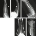
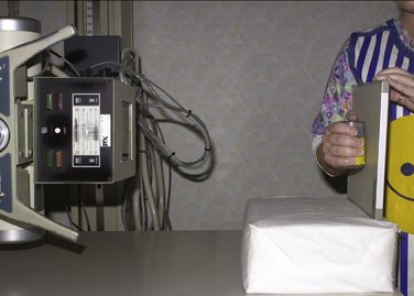
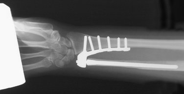
Absence of an intact DRUJ, as occurs after any of the previously mentioned resection procedures, causes the radius to make contact with the distal end of the ulna and “hitch a ride” at this point. This impingement may not be evident on regular posteroanterior radiographs, because the forearm is not loaded in this position. A laterally shot posteroanterior view obtained when the person is holding a weight against gravity with the forearm in the neutral position characteristically brings out the impingement (Fig. 37-1). With this understanding of the anatomy of the ulna, it is not surprising that ulnar head replacements or hemi-arthroplasties are unable to provide an adequate transfer of force when the forearm is in the loaded position.
Patient Selection
Ideal candidates are those individuals in whom the DRUJ cannot be reconstructed. Other requirements are good bone stock with no history of infection in the area, no systemic disease, and no allergy to nickel. Patients may receive the prosthesis at any time after the skeleton is mature; the timing depends on the individual. In some cases, an individual may sustain a fracture that destroys the DRUJ and it is possible to do an immediate reconstruction. However, because it is not yet available in every institution, a delay may be required to obtain the prosthesis.
Surgical Technique
The Prosthesis
The DRUJ prosthesis is a semi-constrained ball-and-socket joint comprising a radial component and an ulnar component (Fig. 37-2).
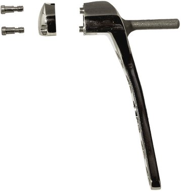
The radial component (Fig. 37-3) provides the socket for the joint and consists of two parts that are assembled intraoperatively. The main part is shaped in the form of a plate with a hemi-socket on the distal end. The body of the plate, with its five screw holes, is contoured to fit against the distal 6 to 7 cm of the interosseous crest, in the area of the sigmoid notch. The plate is fixed to the radius by two means. The first is a peg that is driven into the distal radius in an ulnoradial direction, whereas the second method of fixing the plate involves the use of five specially designed 3.5-mm cortical screws. The hemi-socket, which is part of the plate, is directed ulnarward and is designed to receive the ultra-high-molecular-weight polyethylene ball (UHMWP) of the ulnar component. The other half of the socket, a cover, is separate from the radial component and is fixed to its counterpart on the plate by means of two screws. This assembly encloses the UHMWP ball. The radial component is available in two sizes, small (size 20) and large (size 30), which fit with the corresponding sizes of the ulnar component.
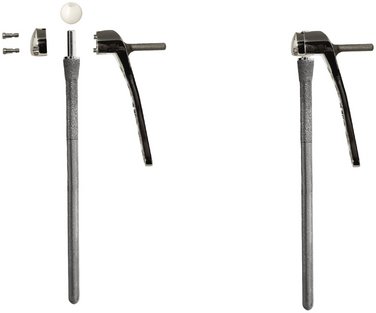
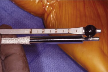
A fluted stem and the UHMWP ball (Fig. 37-4) make up the ulnar component. The ball is placed on the distal end of the stem; this combination replaces the articular surface of the ulnar head. The ulnar stems measure 11 cm in interosseous length, and the distal one third is plasma coated to allow bony ingrowth. A gentle flare at its distal end is present to provide better fixation. The stem is also fluted and slightly tapered to provide rotatory stability and ease of insertion, respectively. The most distal end of the stem bears a highly polished peg or pivot that fits into the hole of the UHMWP ball. The stems are provided in two diameters, 4.5 mm and 5.0 mm, and have correspondingly sized UHMWP balls. Each size couples with the small and large radial components, respectively.

FIGURE 37-4 The ulnar component comprises a fluted stem and an ultra-high-molecular-weight polyethylene (UHMWP) ball.
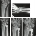
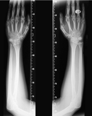
Preoperative graded radiographs are used to determine whether the large or small prosthesis is most likely needed (Fig. 37-5). Digital radiographs can be used if they have accurate measuring capability. The ulna stem size is determined by measuring the narrowest intramedullary diameter of the ulna in its distal 11 cm. A size is chosen that fits this intramedullary diameter best, leaving behind a minimum of 2 mm of cortical bone surrounding the flare of the distal stem. The length of the stem’s extraosseous neck, if one is needed, can also be determined preoperatively with the help of a radiographic measuring template (Fig. 37-6).
Incision Placement and Dissection
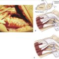
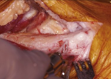
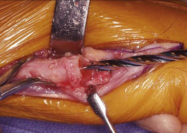
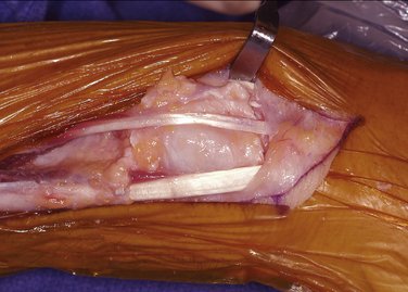
The forearm is placed in full pronation and a 9- to 10-cm hockey stick incision is made above the dorsal lateral aspect of the distal ulna, turning radially just distal to the head of the ulna (Fig. 37-7). Dissection can then either follow the interval between the extensor digiti quinti minimi and extensor carpi ulnaris or the interval between the flexor and extensor carpi ulnaris for added protection of the dorsal sensory branch of the ulnar nerve. If the patient has had surgery in the area, the old incision may be incorporated into the exposure. Taking care to protect the dorsal sensory branch of the ulnar nerve, the incision is then carefully deepened. A fascial/retinacular flap can be created to later provide a barrier between the prosthesis and tendons (Fig. 37-8). The extensor carpi ulnaris tendon sheath is then released from the ulnar head to the insertion of the extensor carpi ulnaris. When approaching the ulna between the extensor carpi ulnaris and the extensor digiti quinti, the extensor digiti quinti is elevated from the ulna and interosseous membrane. The extensor mass is also elevated to expose the interosseous crest of the radius.
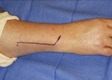
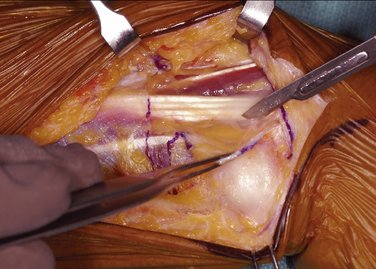
FIGURE 37-8 A dorsal fascial flap is elevated to interpose between the prosthesis and the extensor tendons.
If present, the head of the ulna is then excised at a level just proximal to the head (Fig. 37-9). The radial attachment of the TFC, if found intact, is left undisturbed. If left in situ, this structure can provide a buffering barrier between the prosthesis and the carpus. Excising the ulnar head eases exposure of the radius by allowing the ulnar shaft to be retracted volarward.
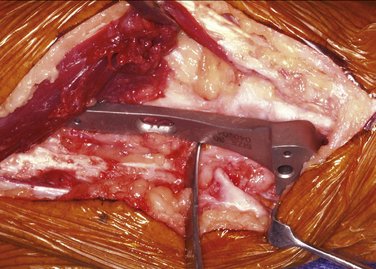
The trial radial plate is then placed over the interosseous surface of the radius. The distal end of the trial plate should be in the area of the sigmoid notch, with the volar edge of the body of the plate aligned with the volar edge of the radius (Fig. 37-10). In cases with radial deformity or a prominent volar lip, a bur can be used to contour the radius for better trial positioning. A minimum of 3 mm is required to separate the distal end of the trial plate and the radiocarpal joint. This space is needed to prevent carpal impingement during ulnar deviation. Proximal positioning is limited by radial width because the radial plate peg is designed to remain within the radius. The volar-facing edge of the trial plate should be on the same plane as the volar surface of the radius. Positioning of the trial plate should also ensure that the plate is not tilted dorsalward or volarward.
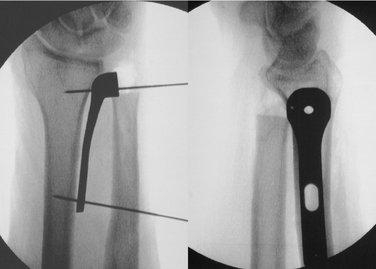
Temporary fixation of the trial plate can be accomplished by using 0.045-inch Kirschner wires (K-wires). Both posteroanterior and lateral positioning is confirmed with an image intensifier (Fig. 37-11). After position confirmation, a 2.5-mm drill bit with the provided guide is used to drill a transverse hole through the sliding guide hole of the trial plate (Fig. 37-12). A depth gauge is used to measure the length of the screws and a 3.5-mm tap is used. None of the screws should more than pierce the outer cortex to prevent possible radial nerve irritation. The oval hole allows for final positioning adjustments, if necessary.
Positioning of the trial plate is again checked and adjustments made if needed. Once the final position is confirmed, the distal K-wire is removed and, using power, the radial peg drill bit is passed through the center distal guide hole of the trial plate. This creates a hole that will accommodate the radial peg portion of the prosthesis (Fig. 37-13).
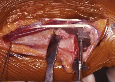
FIGURE 37-13 A dedicated drill bit is used to drill for the radial peg. A stopping plate prevents penetration through the radius.
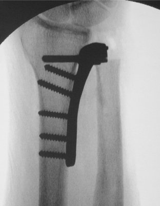
Adequacy of the final position of the trial component is then confirmed (Fig. 37-14). Once satisfied, the trial component is removed and replaced with the radial plate component. Care should be taken to avoid interposition of soft tissue between the plate and the bone. A plastic impactor is provided to protect the face of the plate while using a mallet, if needed, for the radial peg’s insertion (Fig. 37-15). Next, the 3.5-mm screw that was used in the trial plate’s oval hole will be applied to the radial plate’s oval hole. Up to four additional 3.5-mm screws can be used to complete fixation.
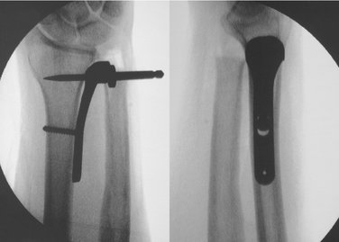
FIGURE 37-14 Image intensifier posteroanterior and lateral views are required before accepting final position of the plate.
It is prudent to keep the most distal screw short to prevent it from potentially impinging against the transverse peg. For this purpose, an 18-mm screw is recommended for use in all cases. Once all screws have been inserted, their length is verified before approaching the ulna (Fig. 37-16).
Resection of the Distal Ulna
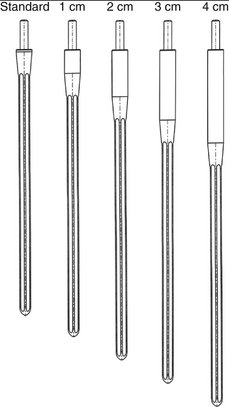
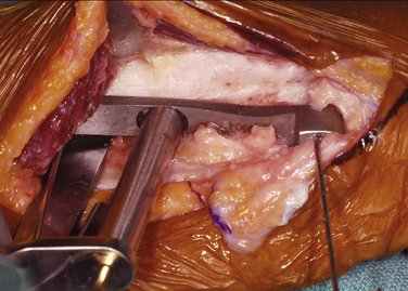
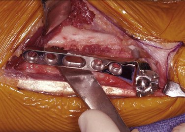
With the forearm fully pronated, a specially designed measuring device is inserted along the ulna and into the hemi-socket of the radial component. The device employs correspondingly sized, removable balls (black for small and blue for large) and enables the surgeon to assess the exact amount of ulnar shaft to be resected. Ulnar resection should be performed through good bone stock. With the measuring device in place, the proximal edge of the metal lip below the ball indicates the appropriate resection level for a standard-length ulnar stem (Fig. 37-17). Once assembled, 1 mm of tolerance should be evident between the ball and the base of the ulnar stem. An extended stem with a suitably lengthened extraosseous neck can then be used when too much bone has been lost due to injury or previous surgery (Fig. 37-18).
For cases with additional ulnar loss (e.g., after trauma or after Darrach or Sauvé-Kapandji procedures), the measuring device is marked in 1-cm increments. This allows the selection of an appropriate length of extended stem (see Fig. 37-18). If the ulnar length falls between marks, it will be resected to the next closest proximal mark. This length should be determined preoperatively using the template.
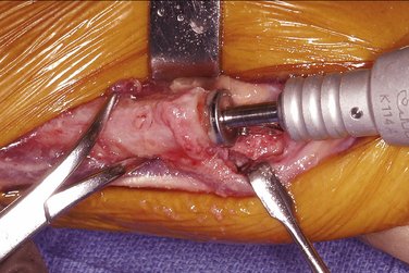
After the appropriate length of the distal ulna has been resected, a 0.062-inch guidewire is inserted into its medullary canal to act as a centralizing guide. Travel of the guidewire should be confirmed with an image intensifier. A cannulated drill bit (either small or large) is then inserted over the guidewire and the medullary canal drilled to a marked length of 11 cm (Fig. 37-19).
Next, the medullary reamer of corresponding size (20 or 30) is inserted into the canal and drilled down until its shoulder comes into contact with the distal end of the ulnar shaft (Fig. 37-20). This completes preparation of the ulnar shaft.
The medullary canal and surrounding soft tissue is profusely and thoroughly irrigated using gravity irrigation. Next, the ulnar stem component is introduced. A plastic impactor is used to protect the polished distal peg of the ulnar stem (Fig. 37-21). If all procedures have been followed, the standard-length stem should be impacted flush with the distal end of the ulna shaft. When an extended stem is indicated, it is impacted until the plasma coating is within the ulna. In cases in which more ulna is resected than intended, care should be taken not to overinsert the selected stem. Leaving a portion of the plasma coating proud of the distal ulna is an option. When in its final position, the distal end of the stem should be no more proximal than the distal end of the radial plate.
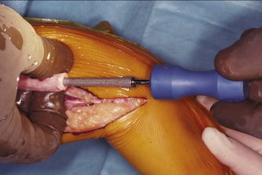
FIGURE 37-21 The ulnar stem is introduced into the ulna, and a plastic impactor is used to protect the stem when using a mallet.
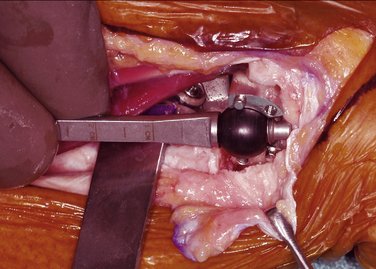
The ulnar component is completed by placing the UHMWP ball over the distal peg of the ulnar stem. This combination replaces the function of the ulna head. The ball and stem are then positioned within the hemi-socket of the radial component, effectively replacing the two articular surfaces of the DRUJ (Fig. 37-22).
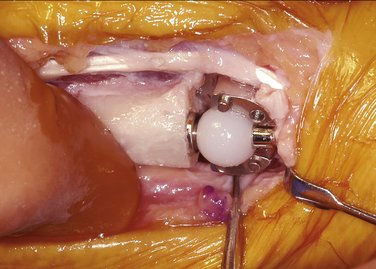
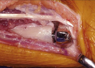
Finally, the cover is positioned over the radial socket and secured with the two screws provided (Fig. 37-23). This encapsulates the UHMWP ball, which recreates the stabilizing effects of an intact TFC and completes the prosthesis.
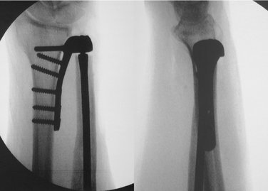
An image intensifier is once again used to confirm adequacy of the overall position of the completed prosthesis (Fig. 37-24). The forearm is moved through a full range of pronation/supination, ensuring free movement. If full motion is not evident, check for any contact of the ulna with the radial plate. If necessary, the ulna can be trimmed to allow full motion. It may also be necessary to release more of the interosseous membrane if it is causing restriction of motion.
The fascial/retinacular flap is now used to cover the prosthesis and create a barrier for the tendons (Fig. 37-25). The tourniquet is released, complete hemostasis is secured, and the wound is closed in a layered fashion. The skin is closed with interrupted sutures. It is recommended that a prophylactic antibiotic be used for approximately 5 days.
A bulky soft tissue dressing is applied with the forearm in neutral position. Immediate limited motion can begin according to patient tolerance. The dressing remains in position for 2 weeks, at which time the sutures are removed and full range of motion exercises are encouraged. Therapy is initiated, if necessary, with active range of motion. Without the possibility of dislocation, patients can both move through a full range of motion and bear weight (Fig. 37-26).
Practical Tips
Results
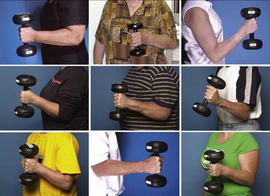
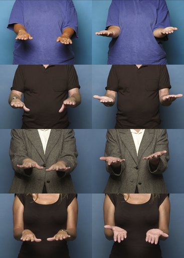
The need for a device to completely replace function of the DRUJ became evident as patient after patient entered the clinic after multiple DRUJ reconstruction and salvage procedures. These patients were at a loss after experiencing an average of 5.5 surgical procedures in an attempt to relieve their pain and instability. Some of the patients with unreconstructable DRUJs had undergone nearly all the described soft tissue, resection, stabilization, and implant arthroplasties combined, none of which provided long-term stability and pain relief. The device described in this chapter was developed as an answer for these patients. It is the only device that replaces the function of three parts of the DRUJ. By replacing the function of the ulnar head, the sigmoid notch, and the TFC, all factors in the joint that could cause instability and pain are eliminated. Preoperatively and postoperatively, the patients were asked to demonstrate not only range of motion but also function, including grip strength and weight-bearing ability. To our knowledge, no current published studies using any other technique test for a patient’s functional ability to bear weight or even measure grip strength (Fig. 37-27). All patients receiving the total DRUJ demonstrated acceptable range of motion (Fig. 37-28) and, more importantly, increased pain-free functional abilities. This improvement included increased grip strength and weight bearing. The goal is not only to relieve pain but also to allow persons with a previously destroyed DRUJ to become once again a functional asset to themselves and society.
If all else, including soft tissue techniques and ulnar shortening, fails, rather than a partial replacement (i.e., replacement of the ulnar head), a total DRUJ replacement like the one presented here is necessary because it will reproduce the function of the sigmoid notch, the ulnar head, and the TFC. We have had experience with over 200 patients who had deranged distal radioulnar joints as a consequence of trauma, congenital abnormality, degenerative arthritis, inflammatory arthritis, and, most frequently, after ulnar head resection had been performed and failed. It has been shown that excision of the head of the ulna leads to impingement and pain with supination and lifting.10 The majority of these patients have had between 2 and 14 procedures on the DRUJ, from partial excision of the DRUJ to wide excision of the ulna, passing through all the techniques of soft tissue stabilization available. Once the total replacement has taken place, the patient has been able to stop taking prescription pain medications and return to a productive life. More than 10 centers have had experience with this device with similar results to ours.
1. Hagert CG. The distal radioulnar joint. Hand Clin.. 1987;3:41-50.
2. Hagert CG. The distal radioulnar joint in relation to the whole forearm. Clin Orthop Relat Res.. 1992;275:56-64.
3. Ark J, Jupiter JB. The rationale for precise management of distal radius fractures. Orthop Clin North Am.. 1993;24:205-210.
4. Wagner H. Proceedings: Corrective surgery after lesions of the distal end of the radius (author’s transl). Langenbecks Arch Chir.. 1973;334:211-219. German
5. Viegas SF. A new modification of corrective osteotomy for treatment of distal radius malunion. Tech Hand Upper Extremity Surg. 2006;10:224-230.
6. Rayhack JM. Ulnar shortening. Tech Hand Upper Extremity Surg. 2003;7:52-60.
7. Scheker LR, Severo A. Ulnar shortening for the treatment of early post-traumatic osteoarthritis at the distal radioulnar joint. J Hand Surg [Br].. 2001;26:41-44.
8. Scheker LR, Belliappa PP, Acosta R, German DS. Reconstruction of the dorsal ligament of the triangular fibrocartilage complex. J Hand Surg [Br].. 1994;19:310-318.
9. Bieber EJ, Linscheid RL, Dobyns JH, Beckenbaugh RD. Failed distal ulna resections. J Hand Surg [Am].. 1988;13:193-200.
10. Lees VC, Scheker LR. The radiological demonstration of dynamic ulnar impingement. J Hand Surg [Br].. 1997;22:448-450.
11. Shaaban H, Giakas G, Bolton M, et al. The distal radioulnar joint as a load-bearing mechanism—a biomechanical study. J Hand Surg [Am].. 2004;29:85-95.
12. Shaaban H, Giakas G, Bolton M, et al. The load-bearing characteristics of the forearm: pattern of axial and bending force transmitted through ulna and radius. J Hand Surg [Br].. 2006;31:274-279.
13. Shaaban H, Giakas G, Bolton M, et al. Contact area inside the distal radioulnar joint: Effect of axial loading and position of the forearm. Clin Biomech. 2007;22:313-318.