[level-membership-for-cardiovascular-category]
CHAPTER 7 Diagnostic Coronary Angiography
ANGIOGRAPHIC VIEWS
In most patients, the right coronary artery is best imaged with a combination of left lateral, cranial left anterior oblique (Cr-LAO), RAO, and Cr-RAO views. Although not used by many cardiologists, the lateral view (Fig. 7-1) has several advantages over a standard 60-degree LAO view because it usually allows better visualization of the mid right coronary artery and collaterals to the left anterior descending artery (LAD). The Cr-LAO view is necessary to lay out the posterior descending artery and posterolateral branches arising from the right coronary artery beyond the posterior descending artery (Fig. 7-2). In patients with large posterolateral branches, the Cr-RAO view projects the posterior descending artery and posterolateral branches clear of each other (Fig. 7-3). Usually, one should not use the Cr-RAO view to the exclusion of the RAO view (Fig. 7-4); however, because the body of the right coronary artery is foreshortened in the Cr-RAO view.
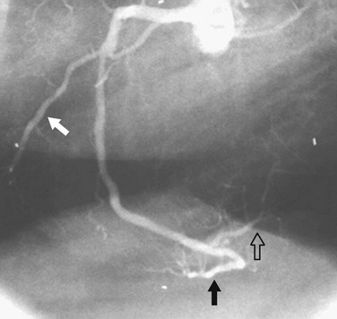
 FIGURE 7-1
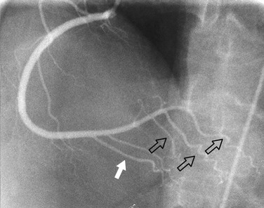
 FIGURE 7-2
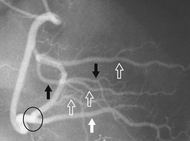
 FIGURE 7-3
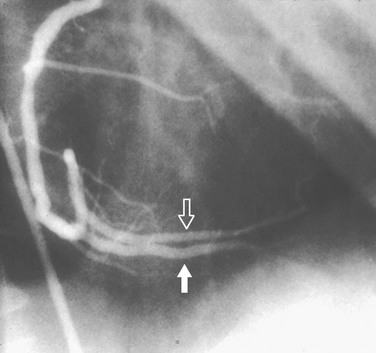
 FIGURE 7-4
In the average patient, the left main coronary artery is projected at true length in either a posteroanterior or a shallow LAO view (Fig. 7-5). The bifurcation and proximal portions of the LAD and left circumflex artery are usually best seen in the Cr-LAO1 (Fig. 7-6) and RAO projections. Enough LAO rotation should be used to place the distal LAD between the spine and the diaphragm. In some individuals, the left main coronary artery has an up-going course. This requires using caudal angulation to eliminate foreshortening. The caudal LAO2 view is the only angiographic view that should be performed with the patient holding his or her breath in expiration (Fig. 7-7). If the patient inspires, the effect of the caudal angulation is negated; this is most common in large patients and requires more exposure than nonangulated views resulting in a degraded image. Because the distal LAD frequently is superimposed on the diaphragm in the Cr-LAO view, a lateral view is often useful (Fig. 7-8).
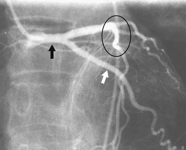
 FIGURE 7-5
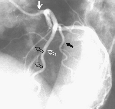
 FIGURE 7-6
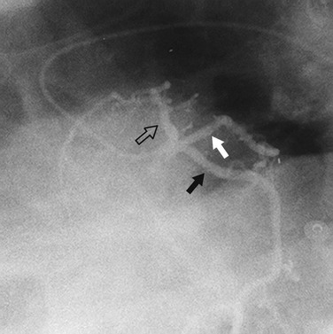
 FIGURE 7-7
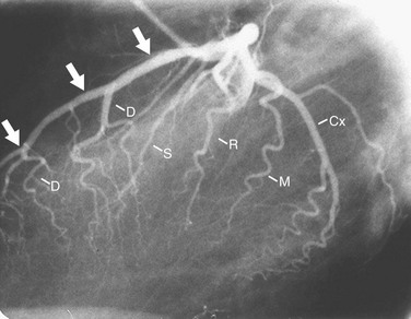
 FIGURE 7-8
At least two RAO views should be obtained in almost all patients. Because the proximal portion of the left circumflex artery curves posteriorly, one must use caudal angulation3 to visualize it and the origins of any proximally arising obtuse marginal branches adequately (Fig. 7-9). With regard to the LAD, the diagonal branches frequently are superimposed on the LAD in the straight RAO view, so cranial angulation of 20 to 25 degrees may be useful (Fig. 7-10).4 The straight RAO view can be added if the distal LAD is poorly visualized in the other RAO views (Fig. 7-11).
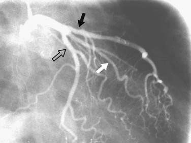
 FIGURE 7-9 Caudal RAO view of the left coronary artery. The proximal portion of the circumflex artery (open arrow) appears longer than in the straight RAO view (see Fig. 7-11). The left anterior descending artery (solid black arrow) and ramus intermedius (solid white arrow) are also well seen.
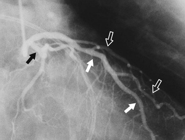
 FIGURE 7-10
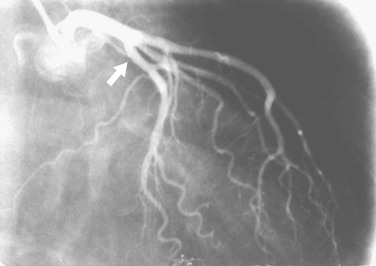
 FIGURE 7-11
IMAGE INTERPRETATION
Coronary atherosclerosis is a diffuse process with focal exacerbations.5 Despite this, the time-honored method of evaluating coronary narrowing is by determination of percent luminal diameter narrowing. This evaluation requires comparing a region of narrowing with that of an adjacent vessel segment that appears to be relatively normal. The normal or reference region may be diffusely narrowed, resulting in underestimation of the degree of stenosis. If there is calcium in the wall of the coronary artery, one may be able to determine the actual diameter of the vessel at that point (Fig. 7-12); however, one still would not know whether that is the true size of the vessel before it became diseased because it may be dilated (see later). Coronary stenoses are rarely concentric, and the severity of narrowing may vary widely in different projections (Fig. 7-13). Some angiographers have tried to circumvent these limitations by calculating percent area narrowing; this still usually requires the assumption that the lesion is concentric, and in my opinion only adds another layer of imprecision to the assessment.
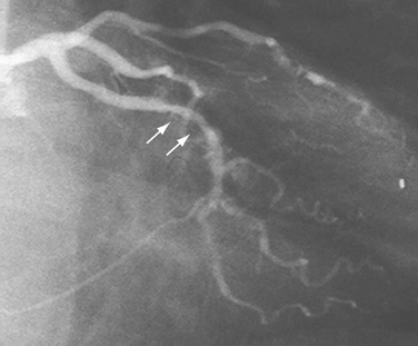
 FIGURE 7-12
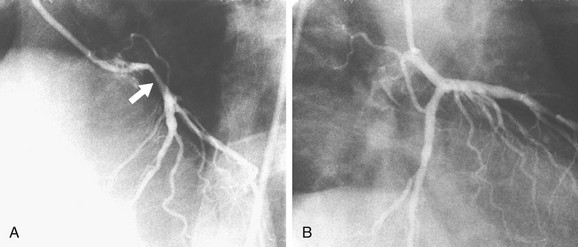
 FIGURE 7-13
Coronary narrowing can be broadly characterized as either discrete or diffuse. We know that atherosclerosis tends to be a diffuse process with focal exacerbations, so when we use the term discrete, it should be understood that we are accepting the limitations of angiography for characterizing lesions. Discrete stenoses (Fig. 7-14) tend to occur in the proximal portions of the epicardial coronary arteries. They may have noncalcified (soft) plaque, calcified (hard) plaque, or a mixture of the two. Soft plaque is less stable than hard plaque and accounts for most acute coronary occlusions. Patients with mostly hard plaque are more likely to present with chronic angina. Angiography does a poor job of distinguishing between the two.
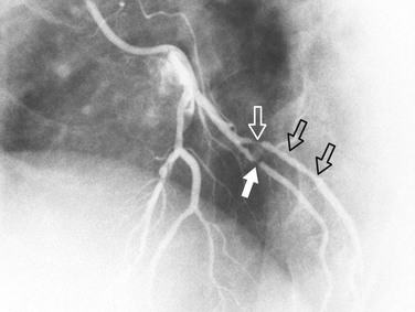
 FIGURE 7-14
Diffuse narrowing is less commonly identified at angiography because of its inability to image the vessel wall. The narrowing may appear to involve only a relatively short distance (Fig. 7-15) or most of a vessel (Fig. 7-16). In the latter case, one may be unable to give an estimate of percent diameter narrowing. As mentioned previously, diffuse narrowing can cause underestimation of the severity of the relatively discrete stenoses occurring either within the diffusely narrowed area or on either end of it. The ability to see the wall of the coronary artery is one of the great advantages of coronary CT angiography compared with conventional coronary angiography.
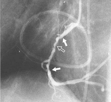
 FIGURE 7-15
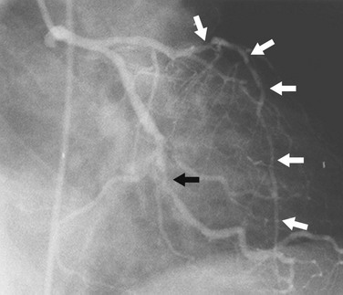
 FIGURE 7-16
In addition to narrowing, atherosclerosis can cause coronary artery enlargement. This enlargement can result from the dilation caused by early remodeling or from atherosclerotic ectasia. With ectasia, the area of dilation may be focal (Fig. 7-17) or diffuse (Fig. 7-18). In either case, it may harbor thrombus. Another problem caused by coronary dilation is that if the chosen reference segment is actually dilated rather than normal, the reference diameter may be greater than in the predisease state, and can result in overestimation of the severity of narrowing.
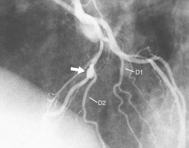
 FIGURE 7-17
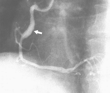
 FIGURE 7-18 LAO view of the right coronary artery shows an area of fusiform dilation (arrow) in the mid-body.
Coronary artery dissection can occur spontaneously or as the result of catheter-induced trauma or balloon angioplasty. The findings are similar to findings seen in aortic dissection with an intimal flap within the coronary lumen (Fig. 7-19). In some cases, the coronary artery may occlude, making the identification of dissection difficult in spontaneous cases.
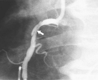
 FIGURE 7-19
Coronary thrombosis typically results from rupture of soft plaque, although it may be seen during coronary intervention and rarely in other circumstances, such as coronary artery compression by a mass or enlarged pulmonary artery. The clot may result in a filling defect within the lumen (Fig. 7-20) or an abrupt occlusion with a concave-appearing proximal border (Fig. 7-21).
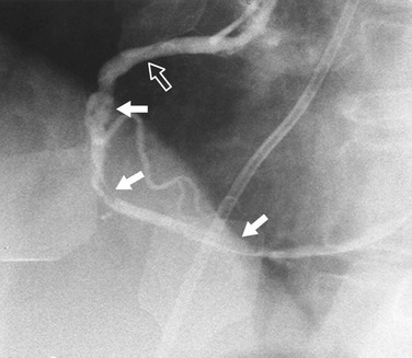
 FIGURE 7-20
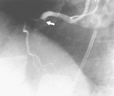
 FIGURE 7-21
Evaluation of collateral flow to a diseased coronary artery is straightforward at angiography and difficult to impossible with coronary CT angiography. Collateral vessels typically are a consequence of slowly developing coronary artery stenosis, but can also be seen more immediately. Intracoronary collaterals directly bridge an obstructed coronary artery segment (Fig. 7-22). Intercoronary collateral vessels connect branches of different coronary arteries or branches of the occluded artery. The myriad intercoronary collateral pathways can seem confusing sometimes, but visualization is easier if one realizes that the connections must be made through shared myocardium. Collateral vessels do not course through the middle of chambers or usually cross another coronary artery. Collateral vessels are typically quite tortuous, but may look almost like a normal coronary artery. Common intercoronary collateral pathways are listed in Table 7-1 and shown in Figures 7-23 through 7-28.
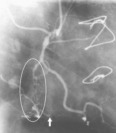
 FIGURE 7-22
| LAD to RCA | LAD to PDA around the apex (see Fig. 7-23) |
|
LAD to acute marginals over RV free wall (see Fig. 7-24) through the interventricular septum (see Fig. 7-25)
|
AV, atrioventricular; LAD, left anterior descending artery; LCx, left circumflex artery; PDA, posterior descending artery; RCA, right coronary artery; RV, right ventricular; SA, sinoatrial.
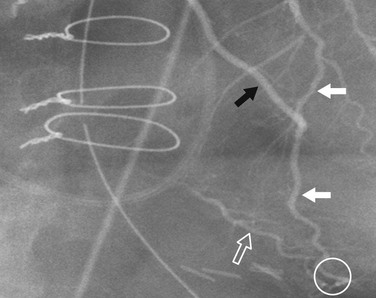
 FIGURE 7-23
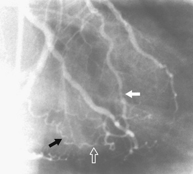
 FIGURE 7-24
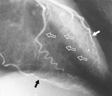
 FIGURE 7-25
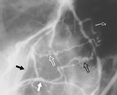
 FIGURE 7-26
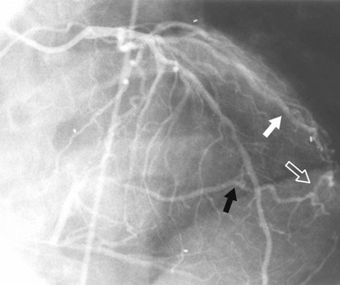
 FIGURE 7-27
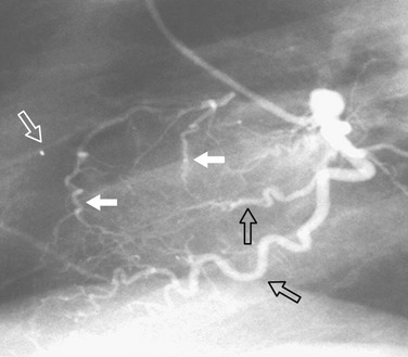
 FIGURE 7-28


1 Bunnell IL, Greene DG, Tandon RN, et al. The half axial projection: a new look at the proximal left coronary artery. Circulation. 1973;48:1151.
2 Elliott LP, Bream PR, Soto B, et al. The significance of the caudal-left anterior oblique view in analyzing the left main coronary artery and its major branches. Radiology. 1981;139:39.
3 Elliott LP, Green CE, Rogers WJ, et al. The importance of angled right anterior oblique views in improving visualization of the coronary arteries. Part I: caudocranial view. Radiology. 1982;142:631.
4 Elliott LP, Green CE, Rogers WJ, et al. The importance of angled right anterior oblique views in improving visualization of the coronary arteries. Part II: craniocaudal view. Radiology. 1982;142:637.
5 Arnett EN, Isner JM, Redwood DR, et al. Coronary artery narrowing in coronary heart disease: comparison of cineangiographic and necropsy findings. Ann Intern Med. 1979;91:350.
[/level-membership-for-cardiovascular-category][not-level-membership-for-cardiovascular-category]
CHAPTER 7 Diagnostic Coronary Angiography
ANGIOGRAPHIC VIEWS
In most patients, the right coronary artery is best imaged with a combination of left lateral, cranial left anterior oblique (Cr-LAO), RAO, and Cr-RAO views. Although not used by many cardiologists, the lateral view (Fig. 7-1) has several advantages over a standard 60-degree LAO view because it usually allows better visualization of the mid right coronary artery and collaterals to the left anterior descending artery (LAD). The Cr-LAO view is necessary to lay out the posterior descending artery and posterolateral branches arising from the right coronary artery beyond the posterior descending artery (Fig. 7-2). In patients with large posterolateral branches, the Cr-RAO view projects the posterior descending artery and posterolateral branches clear of each other (Fig. 7-3). Usually, one should not use the Cr-RAO view to the exclusion of the RAO view (Fig. 7-4); however, because the body of the right coronary artery is foreshortened in the Cr-RAO view.
In the average patient, the left main coronary artery is projected at true length in either a posteroanterior or a shallow LAO view (Fig. 7-5). The bifurcation and proximal portions of the LAD and left circumflex artery are usually best seen in the Cr-LAO1 (Fig. 7-6) and RAO projections. Enough LAO rotation should be used to place the distal LAD between the spine and the diaphragm. In some individuals, the left main coronary artery has an up-going course. This requires using caudal angulation to eliminate foreshortening. The caudal LAO2 view is the only angiographic view that should be performed with the patient holding his or her breath in expiration (Fig. 7-7). If the patient inspires, the effect of the caudal angulation is negated; this is most common in large patients and requires more exposure than nonangulated views resulting in a degraded image. Because the distal LAD frequently is superimposed on the diaphragm in the Cr-LAO view, a lateral view is often useful (Fig. 7-8).
