Dental X-ray generating equipment
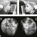
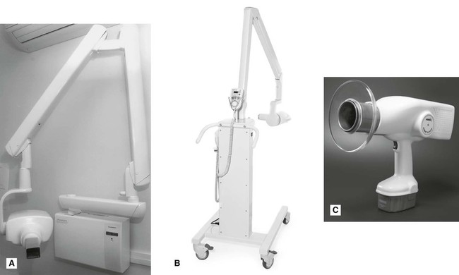
These dental units can either be fixed (wall, floor or ceiling mounted) or mobile (attached to a sturdy frame on wheels) as shown in Figs 3.1A and B. A recent development has been the production of hand-held dental units, as shown in Fig. 3.1C, particularly useful for domiciliary and forensic radiology.
Main components of the tubehead
A diagram of a typical tubehead is shown in Fig. 3.2. The main components include:
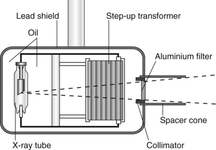
• The glass X-ray tube, including the filament, copper block and the target (see Ch. 2)
• The step-up transformer required to step-up the mains voltage of 240 volts to the high voltage (kV) required across the X-ray tube
• The step-down transformer required to step-down the mains voltage of 240 volts to the low voltage current required to heat the filament
• A surrounding lead shield to minimize leakage
• Surrounding oil to facilitate heat removal
• Aluminium filtration to remove harmful low-energy (soft) X-rays (see Fig. 3.3)
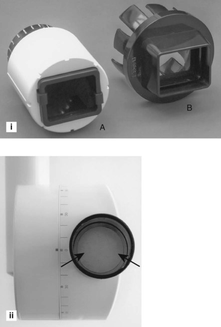
• The collimator – a metal disc or cylinder with central aperture designed to shape and limit the beam size to a rectangle (the same size as intraoral film) or round with a maximum diameter of 6 cm (see Figs 3.3 and 3.4)
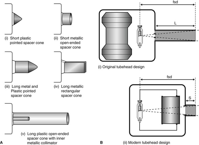
• The spacer cone or beam-indicating device (BID) – a device for indicating the direction of the beam and setting the ideal distance from the focal spot on the target to the skin. The required focus to skin (fsd) distances are:
It is the length of the focal spot to skin distance (fsd), that is important NOT the physical length of the spacer cone. Various designs are illustrated in Fig. 3.4.
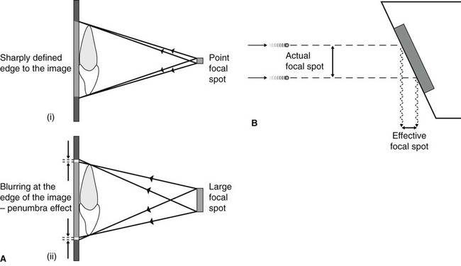
Focal spot size and the principle of line focus
As stated in Chapter 1, the focal spot (the source of the X-rays) should be ideally a point source to reduce blurring of the image – the penumbra effect – as shown in Fig. 3.5A. However, the heat produced at the target by the bombarding electrons needs to be distributed over as large an area as possible. These two opposite requirements are satisfied by using an angled target and the principle of line focus, as shown in Fig. 3.5B.
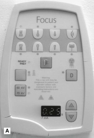
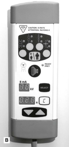
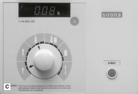
Main components of the control panel
Examples of three typical control panels are shown in Fig. 3.6. The main components include:
 />
/> />
/>
• The mains on/off switch and warning light
• The timer, of which there are three main types:
• An exposure time selector mechanism, usually either:
– numerical, time selected in seconds
– anatomical, area of mouth selected and exposure time adjusted automatically
• Warning lights and audible signals to indicate when X-rays are being generated
Circuitry and tube voltage
The mains supply to the X-ray machine of 240 volts has two functions:
• To generate the high potential difference (kV) to accelerate the electrons across the X-ray tube via the step-up transformer
• To provide the low-voltage current to heat the tube filament via the step-down transformer.
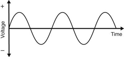
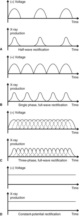
However, the incoming 240 volts is an alternating current with the typical waveform shown in Fig. 3.7. Half the cycle is positive and the other half is negative. For X-ray production, only the positive half of the cycle can be used to ensure that the electrons from the filament are always drawn towards the target. Thus, the stepped-up high voltage applied across the X-ray tube needs to be rectified to eliminate the negative half of the cycle. Four types of rectified circuits are used:
The waveforms resulting from these rectified circuits, together with graphic representation of their subsequent X-ray production, are shown in Fig. 3.8. These changing waveforms mean that equipment is only working at its optimum or peak output at the top of each cycle. The kilovoltage is therefore often described as the kVpeak or kVp. Thus a 50 kVp half-wave rectified X-ray set only in fact functions at 50 kV for a tiny fraction of the total time of any exposure.
Other X-ray generating apparatus
The other common X-ray generating equipment encountered in dentistry includes:
• Panoramic X-ray machines often combined with cephalometric skull equipment (see Ch. 15)
• Skull units, such as the Craniotome® or Orbix® (see Ch. 13)
The main features and practical components of these machines are outlined in later chapters.
To access the self assessment questions for this chapter please go to www.whaitesessentialsdentalradiography.com