Chapter 93 Curative Catheter Ablation for Supraventricular Tachycardia
Techniques and Indications
Accessory Atrioventricular Connections
The anatomic substrate of accessory AV connections is the myocardium bridging the AV annuli, which, in normal individuals, are fibrous and electrically insulating (Box 93-1).1 The sequence of normal initial ventricular septal depolarization is altered by conduction through these connections inserting into the ordinary myocardium and bypassing the normal insulated and septally conducting His-Purkinje system. The relatively slow spread of activation through the ordinary myocardium contrasts with the coordinated septal endocardial breakthrough of Purkinje ramifications and results in the δ-wave in the surface electrocardiogram (ECG). In addition to providing an additional route for impulse conduction between the atria and the ventricles, nearly all accessory connections exhibit conduction properties different from the AV node. Decremental conduction is not ordinarily seen; that is, with increasing frequency or shortening coupling intervals, the conduction time across the pathway does not significantly increase.
Box 93-1 Checklist for Catheter Ablation of Accessory Atrioventricular Connections
Setup
Evaluation
ECG, Electrocardiogram; IVC, inferior vena cava; AV, atrioventricular; VA, ventriculoatrial; SVT, supraventricular tachycardia; AVNRT, atrioventricular nodal re-entrant tachycardia; AP, accessory pathway; RF, radiofrequency.
Electrophysiological Characteristics of Accessory Pathways
During sinus rhythm, ventricular extrastimuli resulting in atrial activation preceding retrograde bundle of His activation indicate an accessory connection. If moving the ventricular pacing site from the apex toward the septum decreases the stimulus to atrial activation time instead of increasing it, an accessory VA connection should be considered. Moving away from the apex increases the conduction time to the normal AV conduction system through the distal Purkinje myocardial interface, whereas it decreases the conduction time to the annular insertion of an accessory pathway.2 Similarly, high output–dependent capture of the insulated right bundle or the bundle of His contrasted with lower output ventricular myocardial capture at the same site can show changes in atrial activation sequence, retrograde His to atrial activation time, and stimulus to atrial activation timing, which suggest the presence of more than one retrograde pathway of VA conduction.3 Unchanged atrial activation sequence coupled with a constant H-A interval and prolongation of the stimulus-A interval resulting from loss of His–right bundle capture indicate the presence of the normal VA conduction alone. Conversely, the absence of change in any of the intervals and sequences indicates the sole presence of accessory pathway retrograde conduction. If the accessory pathway is remote from the pacing site or is captured only with a long conduction time or if conduction through the AV node is very rapid, conduction through the accessory pathway may be completely masked. In practice, left free wall pathways remote from a right ventricular pacing site may fulfill these conditions and are therefore likely to be masked.
During a tachycardia, evidence of conduction through an accessory AV connection can be obtained by delivering late ventricular extrastimuli coincident with or 10 ms before activation of the bundle of His, thus ensuring the encountering of complete refractoriness within the bundle of His. If the extrastimulus is earlier than the His electrogram, the lack of anticipation of the ventricular electrogram, the bundle of His electrogram, or both confirms His-Purkinje refractoriness. The presence of conduction through an accessory connection is indicated if the ventricular extrastimulus advances or delays atrial activation or terminates the tachycardia without conduction to the atria.4 Tachycardia termination by a His-synchronous ventricular extrastimulus without conduction to the atria or with anticipation of the succeeding ventricular or bundle of His electrogram indicates participation of the accessory pathway in the tachycardia.
In addition to establishing the presence of an accessory connection, the electrophysiological study (EPS) allows assessment of the arrhythmogenic potential of the accessory connection. The indications for curative ablation of accessory pathways chiefly depends on their proven threat—pre-excited AF degenerating to VF—or their potential threat, indicated by R-R intervals shorter than 200 to 250 ms during AF or the presence of clinical tachycardias using the accessory pathway.5
Electrophysiological Localization
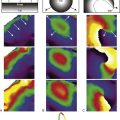
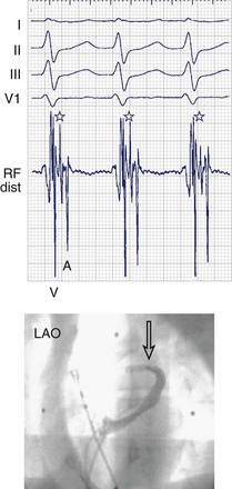
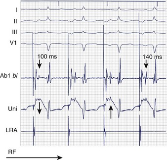
When even the best unipolar and bipolar endocardial electrograms are not good enough, an epicardial or intramyocardial pathway insertion may need to be evaluated or considered. Ventricular electrograms close to or at the site of insertion can be late, not only because the insertion may be far from the endocardium but also because of the endocardial insertion of an oblique pathway. Changing the pacing site (e.g., from the right ventricular apex to the lateral left ventricular or the right ventricular infundibulum) can help distinguish apparently early atrial electrograms (during ventricular pacing) because of an oblique pathway course. Simultaneous comparison of endocardial and epicardial recordings obtained from within the coronary sinus is useful; bracketing, as well as electrogram timing and dv/dt (rate of ventricular electrogram depolarization) comparison, can provide valuable clues. Ablation within the coronary sinus may be necessary (Figure 93-1), although conventional RF delivery achieves only low power and is frequently ineffective. Ablation in the coronary sinus and veins with a catheter with an open irrigated tip can achieve good results; however, stepwise increments in RF power (a cautious maximum of 25 W) are prudent. Pops in the thin-walled coronary venous structure can be devastating; damage to adjacent coronary arteries has also been reported.
Local Electrogram Characteristics
Bipolar and unipolar electrograms should both be used for mapping (Figure 93-2)—the former because of their higher signal/noise ratio and the latter because of their simple morphologic pattern recognition–based analysis.6 Localization based on bipolar electrograms requires distinction of atrial electrograms from ventricular electrograms by using late-coupled ventricular and atrial extrastimuli. However, these maneuvers can be difficult to perform or analyze and may even induce arrhythmias. The contribution of the proximal ring electrode to bipolar electrograms from the distal bipole can be misleading. Atrial electrograms can be distinguished from ventricular electrograms by using unipolar electrograms from the distal electrode.
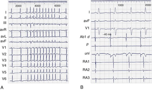
Unipolar electrograms with a steep QS morphology are particularly useful for localizing the site of ventricular insertion on the basis of a steep QS morphology (the absence of an initial R wave) during sinus rhythm, pacing, or even ongoing AF and also in patients with Ebstein’s anomaly who exhibit low-amplitude, fractionated bipolar electrograms on the tricuspid annulus. Unipolar electrograms should be recorded with wide band filters—0.05 to 500 Hz—because the low-frequency content makes important contributions to the generation of RS or QS patterns. Instead of Wilson’s central terminal, a remote cutaneous or inferior vena cava (IVC) electrode may be useful as a ground, allowing common mode rejection of contaminating 50- or 60-Hz line noise. Notch filters should also be used with caution, if at all. Once the atrial and ventricular electrograms have been recognized, the intervening deflections represent presumptive accessory pathway potentials (see Figure 93-1).7 Certainly, the best validation is the prompt abolition of accessory pathway conduction by RF ablation at this site (assuming appropriate power delivery and contact). In practice, accessory pathway potential validation often is a retrospective exercise.
Individual Pathway Locations
Septal Atrioventricular Accessory Connections
The main concern with regard to the mid-septal pathways is to avoid damage to the AV node and the normal conduction axis. As for the para-Hisian pathways, proximity to the bundle of His allows an estimation of this risk. Proximity to the compact AV node is, however, difficult to estimate in the absence of an electrogram marker. The appearance of junctional rhythm is a clear warning that should prompt cessation of RF delivery, and a narrow QRS complex without a preceding P wave should not be mistaken for loss of pre-excitation. Using conventional RF, the strategy for pathways estimated to be close to the AV node or the bundle of His should center around careful mapping for the best electrograms and delivering low RF power at sites thought to be farthest from the conduction axis, usually on the ventricular side of the AV ring. At prospective ablation sites, it is useful to verify the presence and the amplitude of a bundle of His deflection concealed by pre-excitation by using programmed stimulation to induce antegrade pathway block or sustained orthodromic AVNRT. RF power may be increased cautiously in steps of 5 W, but energy delivery should be terminated immediately in case of junctional rhythm or if loss of pre-excitation does not occur promptly. Cryoablation offers the theoretical advantage of reversible cryomapping. In practice, although a greater margin of reversible lesion creation with cryoablation and therefore a lower risk of AV block may exist, this energy source has a clearly higher risk of recovery of pathway conduction.8
The posteroseptal pathways have a higher likelihood of an epicardial course or insertion. Moreover, the anatomic boundaries of the posterior pyramidal space frequently require a choice to be made between the right or left endocardial sites and the sites within the proximal coronary sinus or the middle cardiac vein. A steep QS complex in lead II or an rS complex in leads V5-V6 during pre-excitation may be a clue to an insertion into the middle cardiac vein.9 If endocardial mapping is not good enough or the ablation is unsuccessful, mapping within the coronary sinus and the middle cardiac vein is performed under the guidance of a coronary sinus angiogram. Occlusion balloon angiography provides the best opacification of the great cardiac vein and related branches, but adequate visualization of the proximal coronary sinus and the middle cardiac vein can be achieved from the femoral approach by using an Amplatz catheter. Successful ablation sites are frequently clustered in proximity to venous anomalies such as aneurysms or diverticula. A superior approach from the internal jugular vein provides a relatively straight and vertical catheter course to the middle cardiac vein and should be considered in case of difficulty with the femoral approach. Ablation within the coronary sinus or cardiac veins with a conventional nonirrigated ablation catheter is frequently ineffective because of low delivered powers and high electrode temperatures as a consequence of limited blood flow around the electrode. Ablation in the middle cardiac vein can damage the posterior descending and posterior left ventricular branches of the distal right coronary artery. Ineffective low power delivery can be overcome by using an irrigated tip catheter that allows power to be titrated up to a limit of 25 to 30 W to avoid pops or damage to nearby coronary arteries (within 2 to 3 mm of the site of ablation).
Specific Situations
The substrates of the “Mahaim” pathways (decremental atriofascicular or atrioventricular pathways) and permanent junctional reciprocating tachycardias are both thought to be accessory pathways with long conduction times—antegrade in case of the atriofascicular or AV Mahaim pathways and retrograde in case of persistent junctional reciprocating tachycardia (PJRT). In addition, these two accessory pathway variants share another characteristic—that of one-way conduction only. The few available histologic studies suggest that the anatomic substrate of PJRT is a long and tortuous muscular fascicle, whereas in the case of the Mahaim fiber, an accessory node–like structure is thought to exist at its atrial origin.10 Atriofascicular and AV Mahaim fibers are most effectively ablated by targeting the pathway potentials at the level of the annulus; they resemble the bundle of His potentials but continue to precede ventricular activation even during pre-excitation. PJRT is ablated by targeting the earliest atrial activation during the tachycardia, and, as with every ablation within that posteroseptal area, care must be taken to ensure a reasonable distance from the normal AV conduction axis.
An accessory pathway with a large insertion or an insertion with multiple branches may occasionally be encountered.11 Multiple coalescent lesions, each of which modifies local electrogram parameters, have been used.
Another uncommon variant is an appendage to the ventricular connection characterized by an insertion bridging the appendage tip to the ventricle away from the annulus.12 Careful mapping, aided by three-dimensional mapping as needed, can clarify the exact location of the insertion. Similarly, the unusual variant of surgically acquired pre-excitation is encountered rarely after right atrial appendage anastomosis to the right ventricular outflow tract (RVOT) (historically performed as a palliative procedure for tricuspid atresia). In the appropriate surgical context and with the pre-excited QRS resembling an RVOT tachycardia, careful mapping has allowed successful ablation.
An additional arrhythmia substrate such as AVNRT or AT may coexist. The electrophysiological maneuvers described above can assist in deciding whether the accessory pathway participates in the tachycardia.13 However, in practice, elimination of the accessory pathway substrate typically unmasks the AVNRT or AT, which can then be ablated in the standard fashion.
Indications for catheter ablation include the following:
Atrioventricular Nodal Re-entrant Tachycardias
AVNRT is the result of a re-entry circuit in the AV junctional region (Box 93-2), although debate about anatomic delimitations continues. The functional heterogeneity of AV junctional tissues, primarily with respect to conduction velocity and refractory periods, permits the sustenance of an excitable gap re-entry circuit. Because of anatomic factors and the lack of distinct electrophysiological markers of activation, it is difficult to delineate the anatomic extent of the circuit. Nevertheless, available evidence suggests that the peri-nodal atrium, the compact AV node, and possibly a part of the proximal bundle of His are involved. Although no significant anatomic abnormalities have been found in patients with AVNRT, multiple posteriorly situated pathways or approaches to the AV node have been described.14
Box 93-2 Checklist for Catheter Ablation of AV Nodal Re-entrant Tachycardia
Evaluation
AP, Accessory pathway; AV, atrioventricular; VA, ventriculoatrial; CS, coronary sinus; RF, radiofrequency; AVNRT, atrioventricular nodal re-entrant tachycardia.
At least three different types of AVNRT have been described: (1) slow antegrade/fast retrograde, (2) fast antegrade/slow retrograde, and (3) slow antegrade/slow retrograde. In addition to differences in conduction velocity and refractory periods, the fast and slow pathways manifest relatively disparate anterior and posterior retrograde exit sites, which helps delineate the different types of AVNRT. Most laboratories today establish baseline evidence of antegrade “slow” pathway conduction in the form of a long A-H interval (>200 ms) with or without a discontinuity (50-ms increments in A-H for a 10-ms decrement in coupling interval). In addition, an H-A interval ranging from 25 to 80 ms during tachycardia is indicative of a typical slow-fast AVNRT. Variants of AVNRT (fast-slow or slow-slow) can be distinguished from AVNRT and AT by the response to ventricular extrastimuli introduced during the AV nodal refractory period, by rapid ventricular stimulation, and by the atrial activation sequence and tachycardia behavior during AV block.13
Although fast pathway modification is successful in more than 90% of patients, complete heart block occurs in up to 21%.15 In case of transient conduction block, in-patient telemetric monitoring may be advisable for 1 to 2 days after ablation to watch for delayed complete heart block. The high incidence of AV block and the efficacy of slow pathway ablation have led to this technique being abandoned.
One electrophysiological approach targets the earliest atrial activation during retrograde slow pathway conduction during fast-slow AVNRT or ventricular pacing but is limited by the difficulty in inducing consistent retrograde slow pathway conduction. This is possible in only approximately 10% of patients. More commonly, characteristic electrograms representative of slow pathway conduction have been used to guide RF energy application. Two distinct types of slow pathway potentials have been described. One is a sharp, spikelike potential (Asp) preceded by a lower frequency, lower amplitude potential (A) during sinus rhythm.16 Asp usually follows A by 10 to 40 ms; such double potentials are recorded in the vicinity of the coronary sinus ostium near the tricuspid annulus. During retrograde conduction over the slow pathway, the sequence of these double potentials is reversed, that is, Asp now precedes A. RF energy applied to the latest Asp potential close to the tricuspid annulus successfully eliminated AVNRT in 99% of patients (with only one AV block). Experimental data have shown that similar double potentials are produced by asynchronous activation of muscle bands flanking the mouth of the coronary sinus.17
Other types of the slow pathway potentials are characteristically low-amplitude, low-frequency signals that are concealed within or follow the atrial electrogram and occupy some or all of the A-V interval in sinus rhythm.18 They are easily found by withdrawing the catheter posteriorly from the bundle of His position. In the posterior septum, they are usually hump shaped, whereas more anteriorly they are rapid, narrower, often biphasic, and with a superimposed bundle of His deflection. They are typically recorded at the junction of the anterior two thirds and the posterior one third of the area between the bundle of His and the coronary sinus ostium. During incremental atrial pacing, these slow potentials characteristically separate from the atrial electrograms, are prolonged in duration, and decline in amplitude. They fractionate and disappear at rapid pacing rates so they are not discernible during tachycardia. Animal studies indicate that the low-frequency deflections coincide with the activation of the cells around the tricuspid annulus possessing AV node–like properties. During reverse ventricular echoes, these cells are activated before the earliest atrial activation during retrograde slow pathway conduction but fail to be activated during antegrade conduction over the fast pathway. In view of their wide recording area, they may represent dead-end pathway activation overlying the actively participating cells. Activation of the posterior part of the slow atrio-nodal approaches may give rise to the Asp potential, and the (transitional) tissue anteriorly (beyond the coronary sinus ostium) gives rise to low-frequency slow potentials.
The lower incidence of AV block (approximately 1%) has made slow pathway ablation the technique of choice, although fast pathway ablation may be considered if the slow pathway approach is ineffective. Cautious ablation of the slow pathway is usually effective even in patients with prolonged P-R intervals at baseline because of the persisting so-called “intermediate” pathways that permit AV conduction. Cryoablation is theoretically attractive but has not been shown to be superior and, in fact, has a high incidence of recurrence.19
Atrial Flutter
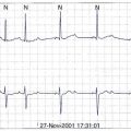
Negative sawtooth flutter waves in leads II, III, and aVF between 200 and 350 beats/min characterize typical atrial flutter (Box 93-3). The absence of a diastolic isoelectric baseline distinguishes it from other SVTs. A typical flutter includes the counterclockwise as well as the clockwise form of the cavotricuspid isthmus–dependent flutter. Beyond this characterization, macro–re-entrant ATs are often considered to be forms of atrial flutter, although they are termed atypical to distinguish them from cavotricuspid isthmus–dependent (typical) flutter.
Box 93-3 Checklist for Catheter Ablation of Typical Atrial Flutter
Typical Atrial Flutter
Modern mapping techniques have merely confirmed the data derived more than 20 years ago that the macro–re-entrant circuit of typical atrial flutter is confined to the right atrium, resulting in counterclockwise or clockwise activation when viewed in the left anterior oblique perspective, with the tricuspid valve en face. In analogy with Mines’ ring models, the tricuspid valve is the outer boundary, and the posterior intercaval right atrium–crista terminalis complex is the inner boundary of a ring of re-entrant activation.20
Ablation of Typical Atrial Flutter
Creation of Linear Lesion
We use a 4-mm ablation catheter with an open irrigated tip for temperature-controlled, sequential, point-by-point RF applications at the isthmus between the IVC and the tricuspid annulus, although ablation catheters with an 8-mm tip have been shown to provide good results as well. A series of linear and contiguous point lesions need to be created to expeditiously achieve complete conduction block. The lesions may be delivered under fluoroscopic guidance, alone or supplemented by nonfluoroscopic navigation (e.g., the Biosense system), with or without the use of long sheaths for superior stability. During counterclockwise flutter, RF may be delivered point by point from the TV annulus on electrograms within the isthmus region coinciding with the center of the surface ECG flutter wave plateau, all the way from the TV annulus to the IVC edge. This ensures a lesion perpendicular to the advancing wavefront and allows catheter displacement to either side to be recognized by the altered timing of the recorded electrogram; for example, in case of lateral displacement, the electrogram coincides with the beginning of the surface ECG plateau, and in case of medial displacement, it coincides with the end of the plateau. During low lateral right atrial pacing in sinus rhythm, sequential RF may be similarly delivered at the 6 o’clock position in the left anterior oblique view in the isthmus on electrograms with a constant stimulus electrogram time from the TV annulus to the IVC edge.21
Merely delivering RF energy at a given location does not guarantee a transmural lesion; the lesion-making ability of RF varies according to contact, local blood flow, delivered power, and myocardial thickness. During unidirectional activation in the atrial myocardium (e.g., in the isthmus during typical flutter or during pacing from the low lateral right atrium or from the ostium of the coronary sinus), a local transmural RF lesion of significant size (comparable with the distal bipole) often can be recognized by double potentials separated by an isoelectric interval; the second potential is produced by activation detouring around the lesion.22
The created lesion size depends on tissue heating, which, in turn, is determined by the current density over a given area. RF power, target temperature, or both may need to be manipulated to achieve transmural lesions at each delivery site. Conventional temperature-controlled RF delivery is subject to variations in local convective cooling, which limits the delivered power either by achievement of the target temperature, by coagulum formation and impedance rise, or by both. Irrigating the ablation electrode substantially reduces the electrode temperature and coagulum formation, thus permitting the delivery of desired (and relatively higher) mean RF power, irrespective of variations in convective cooling. This results in consistent electrogram changes, that is, splitting into double potentials. The use of irrigated-tip catheters with a relatively limited power ceiling (40 W) has been shown to be clinically effective and safe for typical flutter cases resistant to conventional catheter ablation and as a first-line strategy. A significant reduction in procedure and fluoroscopy durations is achieved using irrigated-tip catheters compared with conventional 4-mm tip catheters.23
Identification and Ablation of Residual Gaps
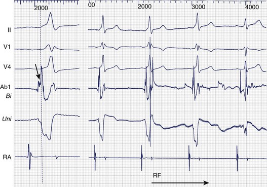
Because of variations in isthmus anatomy and the inability to create consistent continuous transmural lesions, isthmus conduction frequently persists despite anatomically sufficient ablation, flutter termination during RF delivery, or both. Locating and ablating residual gaps in the ablation line is therefore necessary. During typical atrial flutter, such residual gaps can be identified with local electrograms, with a single or a fractionated potential centered on or spanning the isoelectric interval of adjacent double potentials (Figure 93-3). This allows targeted ablation of flutter that recurs after previous ablation. The same approach has been used during pacing from either side of the isthmus, targeting single or fractionated potentials adjacent to double potentials and centered on their isoelectric intervals, with the aim of establishing a continuous corridor of double potentials with isoelectric intervals across the full width of the isthmus.21
Assessment of Isthmus Conduction
Termination of flutter during RF delivery is not a sufficient endpoint because in more than 50% of instances, conduction through the cavotricuspid isthmus persists, resulting in frequent recurrence.24 Transient block or conduction slowing within the isthmus (or ectopics) may be enough to terminate flutter without eliminating the substrate. During pacing from one side of the ablation lesion, a delay in activation on the opposite side and an activation sequence demonstrating a 180-degree change in direction of activation on the other side have been used to diagnose isthmus block. This can be documented sequentially by using rove mapping and simultaneously with a duodecapolar electrode catheter during low lateral atrial or coronary sinus pacing. Local electrogram–based criteria (double potentials) have been shown to be highly sensitive markers of block in the cavotricuspid isthmus.21
The choice of pacing site is instrumental in maximizing the sensitivity and specificity for complete isthmus block and must be as close as possible to the line of block to maximize the sensitivity for detecting slow conduction through the line and avoid it being concealed by the wavefront going around the lesion with a relatively shorter conduction time. This can be easily assessed by the stimulus to the first potential time (st-DP1) on the line; an st-DP1 of 30 ms or less is considered optimal.25 Isthmus block that produces a change in the surface ECG P wave during pacing is greater when pacing from the low lateral right atrium compared with pacing from the coronary sinus ostium. Left atrial activation from the coronary sinus input acts as a surface ECG amplifier of P-wave change during pacing from the low lateral right atrium.
Differential pacing assesses the response of local electrograms (including double and fractionated potentials) to advancing toward or withdrawing the pacing site away from the ablation line.25 If activation on both sides of the line (indicated by local double potentials) is directly linked by a conducting gap, withdrawing the pacing site will increase the activation time to both sides and by roughly the same magnitude. However, if no conducting gap across the line exists, withdrawing the pacing site will certainly increase the activation time upstream of the line. It will either shorten the activation time on the other side of the line or leave it unchanged, but it will not increase it.
Stable conduction block is necessary to avoid recurrence. The probability of conduction recovery across a composite lesion can be estimated by the number of constituent lesions (mean of 6 to 10 point lesions) multiplied by the individual probability of recovery. If the latter is estimated to be 2% (based on data from WPW ablation, the so-called point ablation), this works out to 12% to 20%. Recent data have indicated high rates of conduction recovery after the achievement of complete block (as also after the termination of flutter by RF delivery in the cavotricuspid isthmus). This mandates monitoring of the stability of isthmus conduction block after ablation. The exponential reduction in the incidence of recovery with time suggests an empirical cutoff for the duration of the monitoring period. An extended duration of monitoring (15 to 20 minutes at least) is compatible with the current low recurrence rates observed in our laboratory.24
Atypical Atrial Flutter
Macro–re-entrant ATs other than cavotricuspid isthmus–dependent atrial flutter are termed atypical atrial flutter (Box 93-4).
Diagnostic Criteria
Documentation of less than 60% of the cycle length in the right atrium and evidence of intermittent dissociation of the right atrial free wall from the tachycardia also support the diagnosis of left atrial re-entry.26 Passive activation of the right atrium by septally originating wavefronts colliding on the right atrial free wall is also characteristic. However, conduction block in the cavotricuspid isthmus can mask the lower, septally originating wavefront.
Barriers in the Atria
Some form of fixed or functional central barrier is a prerequisite for re-entry. The wavefront of typical atrial flutter circulates around the posterior intercaval crista terminalis complex. Other naturally occurring barriers in the right atrium include the IVC and the SVC. Acquired barriers in the right atrium include surgical incisions or patches, as well as “mute” regions devoid of electrical activity of uncertain origin.26,27 The role of functional activation inhomogeneities in the right atrium is unclear, although the crista terminalis region has been shown to permit conduction across it during sinus rhythm (as well as during certain forms of re-entry). Each of the above barriers or inhomogeneities—whether functional or fixed—can potentially support a re-entry circuit around it, provided that an appropriate trigger is present and the conditions of sufficient conduction times (wavelength) around it are met.
The left atrium has little evidence of a naturally present zone of block or slow conduction and certainly lacks the anatomic equivalent of a crista terminalis. Perhaps as a result, left atrial macro–re-entry in the absence of structural heart disease, surgery, or catheter ablation is far less common than typical atrial flutter. Left atrial flutter occurs in predominantly two situations: (1) as a sequel to ablation in the left atrium and (2) in subjects with left-sided structural heart disease.26 Characteristically, most patients have more than one ECG arrhythmia morphology (hence circuit) of re-entry, correlating with the frequent demonstration of multiple loop re-entry. Anatomic obstacles such as the pulmonary veins or the mitral valve, buttressed centrally or laterally by linear ablation lesions, form the core of the circuit. Although these macro–re-entrant circuits are large in diameter (approximately 5 cm), other small (1- to 1.5-cm diameter) re-entrant circuits have been observed around a pulmonary vein ostium or an incomplete lesion at the pulmonary vein ostium.28 In patients without prior left atrial ablation, macro–re-entrant circuits frequently are anchored around relatively large electrically silent areas, in addition to anatomic obstacles such as the pulmonary veins and the mitral valve. Although the exact nature of these “mute zones” remains to be determined, infarction or a myocarditic inflammatory scar have been evoked. Coronary angiography has, however, failed to show an appropriately located coronary occlusion (or lesion), and in the absence of other evidence of myocarditis, other, perhaps hemodynamic (related to elevated pressures), reasons may be operative.
Intracardiac Mapping
The characteristics of the line of block resulting from the surgical atriotomy on the right atrial free wall played a significant role in determining the kind of arrhythmia circuit that developed.29 A right atrial free wall peri-atriotomy re-entry circuit was more likely to occur if the scar was relatively long, resulting in a restricted isthmus bounded inferiorly by the IVC, and if the scar was vertical or oblique and relatively anteriorly placed. Nearly all these patients with a free wall circuit also had peri-tricuspid re-entry. Isolated peri-tricuspid re-entry was observed when no electrophysiological evidence of a right atrial free wall atriotomy was found or if this scar was too small or posteriorly placed. If the right atrial free wall atriotomy is long enough to extend to the IVC inferiorly, thus eliminating the inferior isthmus, peri-atriotomy re-entry cannot occur. It is not clear whether the near-universal presence of peri-tricuspid re-entry in this cohort of patients is caused by diffuse substrate alterations or results from the presence of a (posteriorly placed) atriotomy buttressing the often-functional block zone of the crista terminalis.
Patients with pronounced hemodynamic loads, for example, after corrective or palliative surgery such as the Fontan procedure, have the substrate for re-entry in the form of small channels or isthmuses in the altered milieu of a low-voltage area of the right atrial free wall.30 It may be difficult to distinguish multiple small channels within this low-voltage area without three-dimensional mapping, and mapping during different rhythms may be necessary to detect as many potential isthmuses as possible. Despite the frequent presence of surgical incisions in the septum, re-entry in this anatomic location is infrequent.
Left Atrial Substrate
Re-entry within the left atrium typically is related to scars from surgery or catheter ablation or is associated with structural heart disease. A detailed account of the surgical or catheter ablation procedure is useful to allow optimal mapping within a particular region of interest. Gaps of persisting conduction across linear or isolating lesions are the typical substrate of isthmuses and can be easily recognized by fractionated “diastolic” electrograms coinciding with synchronous isoelectric intervals in all 12 ECG leads.28 These isthmuses usually support small-diameter (1 to 1.5 cm) re-entrant circuits. Less frequently, large re-entrant circuits depend on such small, slow conducting isthmuses. Large circuits typically are the result of wide isthmus re-entry around anatomic barriers or anatomic plus lesion-based barriers. In our experience, they are typically associated with severe left atrial dilation, linear lesions in the left atrium, or both. Multiple linear lesions in the left atrium frequently are associated with the greatest likelihood of multi-loop re-entry.
Non–re-entrant Atrial Tachycardias
This arrhythmia subset must be distinguished from re-entrant AT because the approach to successful ablation is clearly different (Box 93-5).
Box 93-5 Checklist for Catheter Ablation of Non–Re-entrant Atrial Tachycardia
The major difference is a radial pattern of activation during these tachycardias.31 For practical purposes, the atria, unlike the ventricles, can be considered to be two dimensional. The absence of electrical activity spanning a significant part of the cycle length indicates a diastolic pause characteristic of abnormal impulse generation resulting from triggered activity or abnormal automaticity. This deduction presupposes an adequate and complete exploration of the endocardium, including the great thoracic veins; the coronary sinus should not be considered a surrogate for the left atrium. Mapping reveals radial atrial activation confined to electrical systole, that is, coinciding with the surface ECG P wave. The sequence of activation of the two bipoles of the rove mapping and ablation catheter can be useful; a distal-to-proximal activation persisting with catheter advancement indicates a vector originating from that direction, whereas a proximal-to-distal activation sequence suggests that the wavefront originates from the direction of the proximal bipole. An iterative mapping sequence documenting the transition from the former to the latter activation direction is characteristic of the source of radial activation and requires returning to the initial catheter position.
The inference of a non–re-entrant mechanism is further strengthened by a pattern of arrhythmia bursts with cycle length irregularity, warm-up behavior, or both, unlike a stable re-entrant mechanism (see Figure 93-4). Identical activation sequences for the first and subsequent beats of the tachycardia further support a non–re-entrant mechanism. If the arrhythmia is sustained, demonstration of entrainment is supportive of re-entry. If the re-entry circuit is small, radial activation of the rest of the atria cannot be distinguished from a non–re-entrant mechanism. Therefore recognition of small re-entry circuits depends on the mapping resolution. If the arrhythmia source is confined to an unmapped area (e.g., in the left atrium or within the SVC), the arrhythmia mechanism may be difficult to recognize. Unlike re-entry, pacing maneuvers—typically overdrive—suppress the non–re-entrant tachycardia without demonstrating the classic features of entrainment with progressive fusion. In the experimental laboratory, termination of the tachyarrhythmia by sectioning a critical part of the circuit is a highly specific evidence of re-entry, but clinically, the difficulty in consistently achieving a completely transmural incision such as a lesion by RF delivery reduces the value of this criterion.
The surface ECG with a clearly visible P wave in all 12 leads is highly valuable for localizing the origin of the tachycardia. A clear isoelectric baseline separating individual P waves is compatible with non–re-entrant mechanisms; however, some very rapid non–re-entrant tachycardias may not exhibit a baseline. P-wave polarity in leads V1, I, and aVL is important in assigning the atrium of origin.32 A late positive, dominantly positive, or completely positive P wave in lead V1 indicates left atrial origin.33 Septally originating tachycardias exhibit narrower P waves, and the frontal plane axis is helpful as it indicates a superior or inferior origin. Localization can be further refined with the help of pacemapping by using both the surface ECG as well as patterns of intracardiac activation.
Multi-catheter activation mapping allows quicker assessment of approximate localization, although the selection of an appropriate ablation site still requires careful mapping and sufficient arrhythmia. The optimal ablation site is one with the earliest bipolar and unipolar activation, although the issue of determining the early enough timing remains. A timing preceding the surface ECG onset of the P wave with a QS morphology on the unipolar electrogram and that does not precede bipolar activation at that site is usually necessary (see Figure 93-4).
In most instances, focal ablation suffices and arrhythmia elimination and noninducibility are the only endpoints. Venous tachycardia (which can be either re-entrant or non–re-entrant) is a specific situation, particularly a pulmonary vein tachycardia, which can even trigger and maintain AF. An expeditious solution is to disconnect the vein from the left atrium (right atrium in case of the SVC), making sure that the disconnection is proximal to the source of the arrhythmia.34 This endpoint is useful even with arrhythmia that is difficult to induce.
Key References
Haissaguerre M, Dartigues JF, Warin JF, et al. Electrogram patterns predictive of successful catheter ablation of accessory pathways. Value of unipolar recording mode. Circulation. 1991;84(1):188-202.
Haissaguerre M, Gaita F, Fischer B, et al. Elimination of atrioventricular nodal reentrant tachycardia using discrete slow potentials to guide application of radiofrequency energy. Circulation. 1992;85(6):655-656.
Jackman WM, Beckman KJ, McClelland JH, et al. Treatment of supraventricular tachycardia due to atrioventricular nodal reentry, by radiofrequency catheter ablation of slow pathway conduction. N Engl J Med. 1992;327(5):313-318.
Jackman WM, Friday KJ, Yeung-Lai-Wah JA, et al. New catheter technique for recording left free wall accessory atrioventricular pathway activation. Identification of pathway fiber orientation. Circulation. 1988;78:598-611.
Jais P, Shah DC, Haissaguerre M, et al. Mapping and ablation of left atrial flutters. Circulation. 2000;101(25):2928-2934.
Klein GJ, Bashore TM, Sellers TD, et al. Ventricular fibrillation in the Wolff-Parkinson-White syndrome. N Engl J Med. 1979;301(20):1080-1085.
Nakagawa H, Shah N, Matsudaira K, et al. Characterization of reentrant circuit in macroreentrant right atrial tachycardia after surgical repair of congenital heart disease: Isolated channels between scars allow “focal” ablation. Circulation. 2001;103(5):699-709.
Sellers TDJr, Gallagher JJ, Cope GD, et al. Retrograde atrial preexcitation following premature ventricular beats during reciprocating tachycardia in the Wolff-Parkinson-White syndrome. Eur J Cardiol. 1976;4:283-294.
Shah DC, Haissaguerre M, Jais P, et al. High density mapping of activation through an incomplete isthmus ablation line. Circulation. 1999;99(2):211-215.
Shah D, Jais P, Takahashi A, et al. Dual loop intra-atrial reentry in humans. Circulation. 2000;101(6):631-639.
Shah DC, Takahashi A, Jais P, et al. Local electrogram based criteria of cavotricuspid isthmus block. J Cardiovasc Electrophysiol. 1999;10(5):662-669.
Tang CW, Scheinman MM, Van Hare GF, et al. Use of P wave configuration during atrial tachycardia to predict site of origin. J Am Coll Cardiol. 1995;26(5):1315-1324.
Tchou P, Lehmann MH, Jazayeri M, Akhtar M. Atriofascicular connection or a nodoventricular Mahaim fiber? Electrophysiological elucidation of the pathway and associated reentrant circuit. Circulation. 1988;77:837-848.
Yamane T, Shah DC, Peng JT, et al. Morphological characteristics of P waves during selective pulmonary vein pacing. J Am Coll Cardiol. 2001;31(5):1505-1510.
1 Gallagher JJ, Pritchett ELC, Sealy WC, et al. The preexcitation syndromes. Prog Cardiovasc Dis. 1978;20:285-327.
2 Martinez-Alday JD, Almendral J, Arenal A, et al. Identification of concealed posteroseptal Kent pathways by comparison of ventriculoatrial intervals from apical and posterobasal right ventricular sites. Circulation. 1994;89:1060-1067.
3 Hirao K, Otomo K, Wang X, et al. Para-Hisian pacing. A new method for differentiating retrograde conduction over an accessory AV pathway from conduction over the AV node. Circulation. 1996;94:1027-1035.
4 Sellers TDJr, Gallagher JJ, Cope GD, et al. Retrograde atrial preexcitation following premature ventricular beats during reciprocating tachycardia in the Wolff-Parkinson-White syndrome. Eur J Cardiol. 1976;4:283-294.
5 Klein GJ, Bashore TM, Sellers TD, et al. Ventricular fibrillation in the Wolff-Parkinson-White syndrome. N Engl J Med. 1979;301(20):1080-1085.
6 Haissaguerre M, Dartigues JF, Warin JF, et al. Electrogram patterns predictive of successful catheter ablation of accessory pathways. Value of unipolar recording mode. Circulation. 1991;84(1):188-202.
7 Jackman WM, Friday KJ, Yeung-Lai-Wah JA, et al. New catheter technique for recording left free wall accessory atrioventricular pathway activation. Identification of pathway fiber orientation. Circulation. 1988;78:598-611.
8 Kirsh JA, Gross GJ, O’Connor S, et al. Transcatheter cryoablation of tachyarrhythmias in children: Initial experience from an international registry. J Am Coll Cardiol. 2005;45:133-136.
9 Takahashi A, Shah DC, Jais P, et al. Specific electrocardiographic features of manifest coronary vein posteroseptal accessory pathways. J Cardiovasc Electrophysiol. 1998;9(10):1015-1025.
10 Tchou P, Lehmann MH, Jazayeri M, Akhtar M. Atriofascicular connection or a nodoventricular Mahaim fiber? Electrophysiological elucidation of the pathway and associated reentrant circuit. Circulation. 1988;77:837-848.
11 Gaita F, Haissaguerre M, Scaglione M, et al. Catheter ablation in a patient with a congenital giant right atrial diverticulum presenting as Wolff-Parkinson-White syndrome. Pacing Clin Electrophysiol. 1999;22(2):382-385.
12 Goya M, Takahashi A, Nakagawa H, Iesaka Y. A case of catheter ablation of accessory atrioventricular connection between the right atrial appendage and right ventricle guided by a three dimensional electroanatomic mapping system. J Cardiovasc Electrophysiol. 1999;10(8):1112-1118.
13 Veenhuyzen GD, Coverett K, Quinn FR, et al. Single diagnostic pacing maneuver for supraventricular tachycardia. Heart Rhythm. 2008;5:1152-1158.
14 Wu J, Wu J, Olgin J, et al. Mechanisms underlying the reentrant circuit of atrioventricular nodal reentrant tachycardia in isolated canine atrioventricular nodal preparations using optical mapping. Circ Res. 2001;88(11):1189-1195.
15 Jazayeri MR, Hempe SL, Sra JS, et al. Selective transcatheter ablation of the fast and slow pathways using radiofrequency energy in patients with atrioventricular nodal reentrant tachycardia. Circulation. 1992;85(4):1318-1328.
16 Jackman WM, Beckman KJ, McClelland JH, et al. Treatment of supraventricular tachycardia due to atrioventricular nodal reentry, by radiofrequency catheter ablation of slow pathway conduction. N Engl J Med. 1992;327(5):313-318.
17 McGuire MA, de Bakker JM, Vermeulen JT, et al. Origin and significance of double potentials near the atrioventricular node. Correlation of extracellular potentials, intracellular potentials, and histology. Circulation. 1994;89(5):2351-2360.
18 Haissaguerre M, Gaita F, Fischer B, et al. Elimination of atrioventricular nodal reentrant tachycardia using discrete slow potentials to guide application of radiofrequency energy. Circulation. 1992;85(6):655-656.
19 De Sisti A, Tonet J, Gueffaf F, et al. Effects of inadvertent atrioventricular block on clinical outcomes during cryoablation of the slow pathway in the treatment of atrioventricular nodal re-entrant tachycardia. Europace. 2008;10(12):1421-1427.
20 Shah DC, Jais P, Haissaguerre M, et al. Three dimensional mapping of the common atrial flutter circuit in the right atrium. Circulation. 1997;96(11):3904-3912.
21 Shah DC, Takahashi A, Jais P, et al. Local electrogram based criteria of cavotricuspid isthmus block. J Cardiovasc Electrophysiol. 1999;10(5):662-669.
22 Shah DC, Haissaguerre M, Jais P, et al. High density mapping of activation through an incomplete isthmus ablation line. Circulation. 1999;99(2):211-215.
23 Jais P, Shah DC, Haissaguerre M, et al. Prospective randomized comparison of irrigated tip versus conventional tip catheters for ablation of common flutter. Circulation. 2000;101(7):772-776.
24 Shah DC, Takahashi A, Jais P, et al. Tracking dynamic conduction recovery across the cavotricuspid isthmus. J Am Coll Cardiol. 2000;35(6):1478-1484.
25 Shah D, Haissaguerre M, Takahashi A, et al. Differential pacing for distinguishing block from persistent conduction through an ablation line. Circulation. 2000;102(13):1517-1522.
26 Jais P, Shah DC, Haissaguerre M, et al. Mapping and ablation of left atrial flutters. Circulation. 2000;101(25):2928-2934.
27 Shah D, Jais P, Takahashi A, et al. Dual loop intra-atrial reentry in humans. Circulation. 2000;101(6):631-639.
28 Shah D, Sunthorn H, Burri H, et al. Narrow, slow-conducting isthmus dependent left atrial reentry developing after ablation for atrial fibrillation: ECG characterization and elimination by focal RF ablation. J Cardiovasc Electrophysiol. 2006;17(5):508-515.
29 Shah DC, Jais P, Hocini M, et al. Catheter ablation of atypical right atrial flutter. In Zipes DP, Haissaguerre M, editors: Catheter ablation of arrhythmias, ed 2, Armonk, NY: Futura publications, 2001.
30 Nakagawa H, Shah N, Matsudaira K, et al. Characterization of reentrant circuit in macroreentrant right atrial tachycardia after surgical repair of congenital heart disease: Isolated channels between scars allow “focal” ablation. Circulation. 2001;103(5):699-709.
31 Goldreyer BN, Gallagher JJ, Damato AN. The electrophysiologic demonstration of atrial ectopic tachycardia in man. Am Heart J. 1973;85:205-215.
32 Tang CW, Scheinman MM, Van Hare GF, et al. Use of P wave configuration during atrial tachycardia to predict site of origin. J Am Coll Cardiol. 1995;26(5):1315-1324.
33 Yamane T, Shah DC, Peng JT, et al. Morphological characteristics of P waves during selective pulmonary vein pacing. J Am Coll Cardiol. 2001;31(5):1505-1510.
34 Shah DC, Haissaguerre M, Jais P, Clementy J. High resolution mapping of tachycardia originating from the superior vena cava: Evidence of electrical heterogeneity, slow conduction, and possible circus movement reentry. J Cardiovasc Electrophysiol. 2002;13(4):388-392.
35 Blomström-Lundqvist C, Scheinman MM, Aliot EM, et al. ACC/AHA/ESC guidelines for the management of patients with supraventricular arrhythmias—executive summary: A report of the American College of Cardiology/American Heart Association Task Force on Practice Guidelines and the European Society of Cardiology Committee for Practice Guidelines. Circulation. 2003;108(15):1871-1909.