[level-membership-for-hematology-oncology-and-palliative-medicine-category]
Chapter 15 Conformal Therapy and Intensity-Modulated Radiation Therapy
Treatment Planning, Treatment Delivery, and Clinical Results
Conformal Therapy Definitions
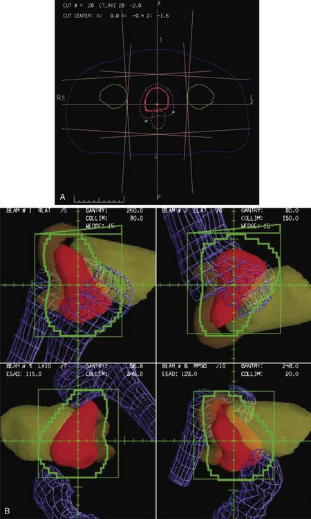
Conformal therapy describes radiotherapy treatment that creates a high-dose volume that is shaped to closely “conform” to the desired target volumes while minimizing (as much as possible) the dose to critical normal tissues. A more recent enhancement of the definition of conformal therapy incorporates the fact that the conformal plan is designed to conform to all the target dose requirements (shape; a possibly complex, desired dose distribution inside the target) while minimizing the normal tissue doses. Although these features are the general aim of any radiotherapy treatment, normally the term conformal is applied to treatment plans in which (1) the target volumes are defined in three dimensions using contours drawn on many slices from a computed tomography (CT) (or other) imaging study, (2) multiple beam directions are used to cross fire on the targets, (3) the individual beams are shaped or intensity modulated to create a dose distribution that conforms (in shape and dose) to the target volume shape(s) and desired dose levels, and (4) appropriate use is made of image guidance, accurate patient setup and immobilization, and management of motion and other changes to ensure accurate delivery of the planned dose distributions to the patient, so that deviations from the planned treatment of the patient are minimized. Figure 15-1 illustrates the conceptual difference between standard and conformal therapy: Figure 15-1A shows a standard four-field box treatment for a given target volume that everyone would agree is a nonconformal approach, whereas Figure 15-1B shows a conformal approach achieved with conformally shaped fields.
A Short History Of Conformal Therapy
One of the most important pioneers in “conformation therapy” was Shinji Takahashi, who described many of the important concepts of conformal therapy delivery and 3D treatment planning in a 1965 monograph.1 Takahashi’s innovations included early multileaf collimators, automated (mechanical) conformal beam shaping, dynamic conformal treatments, orthogonal light beams to identify the machine isocenter, and 3D tumor models based on early tomography.1 Other notable work in this area was performed by Harold Perry and colleagues2 in Detroit and by Proimos, Wright, and Trump at the Massachusetts Institute of Technology (MIT)–Lahey Clinic.3–7 Another early approach to conformal therapy, known as the Tracking Cobalt Project,8,9 was led by Green, Jennings, and others at the Royal Northern and Royal Free Hospitals in England. First reported in the late 1950s,10 and summarized by Jennings,8 a series of mechanical, electronic, and, finally, computer-controlled treatment machines were developed to track disease spread, particularly along lymph node chains. By 1980, the computer-controlled version of the tracking system was in clinical use,11 although Brace summarized the major limitations to the delivery technique: “The major obstacle to the routine use of conformation therapy is treatment planning.”11 Finally, workers at the Joint Center for Radiation Therapy (JCRT) in Boston added computer control to a modern linear accelerator, so that the treatment table, gantry, collimator, collimator jaws, dose rate, and other parameters could be controlled dynamically while the beam was in use. The JCRT achieved the delivery of what is now called “dynamic conformal therapy,”12–1415 a modern basis for computer-controlled conformal therapy.
As already described in the quote (above) by Brace, treatment planning was one of the main limitations for the conformal delivery techniques that were developed during this time period. The introduction of computed tomography (CT) in the early 1970s was a key to the development of the modern 3D planning that is crucial to conformal therapy, because it made available a complete 3D description of the anatomy of each patient that could be the basis for planning. Early evaluation of the use of CT in treatment16–18 quickly led to widespread use of CT-based planning (see Ling19) as well as new interest in the use of inhomogeneity-corrected dose calculations, because CT provided the necessary electron-density maps of the patient.20 Other imaging data, including magnetic resonance imaging (MRI) and positron emission tomography (PET), also became available and began to be used for planning in the mid-1980s.21
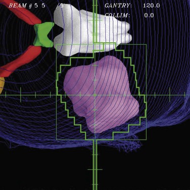
With the widespread implementation of CT-based planning, it became possible to make use of continuing improvements in computer technology and new software developments to create fully 3D treatment planning systems that incorporated 3D graphics and the “beam’s-eye view” (BEV), a 3D graphic reconstruction of the patient anatomy projected into the divergent geometry used by the x-rays in the radiation beam22–26 (Fig. 15-2). Using BEV displays to design field shaping27 and evaluate coverage of tumor and sparing of normal tissues is perhaps one of the most effective concepts in the entire 3D planning paradigm. Routine clinical use of 3D radiation treatment planning (RTP) began in 1986,28 and many academic centers began development and then use of 3D planning systems in their clinics.29–32
The development of 3D treatment planning systems helped drive the need for and design of more sophisticated treatment delivery systems because the 3D planning systems demonstrated treatment improvements that would be possible to use clinically if more sophisticated machinery were available to make efficient delivery possible. The first treatment machine designed specifically to perform computer-controlled conformal radiotherapy (CCRT), the Scanditronix MM50 Racetrack Microtron, was developed during this same time period.33,34,35 Among other unique features, this machine included a fully computerized control system and a computer-controlled multileaf collimator (MLC)36 consisting of two sets of thin tungsten leaves that are used to shape the radiation field. Virtually all other radiation therapy machines have since that time also implemented computer control systems and MLC systems.37–39
The capabilities of computer control and MLC systems have made possible the delivery of very complicated plans, including those that make use of modulated intensities (a beam with different intensities in different parts of the field). Intensity modulation created using multiple segments40–43,44,45 or dynamic MLC motions33,46,47 and computer plan optimization (inverse planning)48,49–51,52 have been integrated into IMRT.53 The basic concepts of IMRT were described in 1987 by Brahme33,48,54 and a practical implementation was described by Bortfeld soon after.55 The combination of the flexibility of computer-controlled IMRT delivery with sophisticated plan optimization techniques has made IMRT an extremely powerful tool that can be used to perform conformal therapy.
The initial commercial IMRT implementation by NOMOS in 199256 was a form of IMRT now called serial tomotherapy, in which patients were treated slice by slice (as with early CT scanners) by the machine rotating around the patient and a special multileaf collimator (MIMIC) that performed the intensity modulation. Within a few years, all major vendors had implemented MLC systems with leaf widths varying from 1 cm to a few millimeters that could perform IMRT using either dynamic motions of the MLC leaves (DMLC) or a number of static segments (shapes), now called SMLC.53 A more sophisticated implementation of tomotherapy based on helical delivery of IMRT, helical tomotherapy,57 also became widely disseminated. In the last several years, a number of vendors have now developed a rotational MLC-based IMRT technique (IMAT), which was originally described by Yu,58 and is now called VMAT (volumetric modulated arc therapy).59,60 Inverse planning has also developed substantially during this time. Though much of this optimization makes use of quadratic weighted sum cost functions and simple gradient-based search algorithms, there have also been developments of sophisticated cost functions61 and the use of more biologically related costs such as normal tissue control probability (NTCP) models and equivalent uniform dose (EUD). Most systems use the weighted sum cost functions, but there has been development of sophisticated multicriteria methods62,63 that more directly take into account the numerous optimization goals involved in a typical clinical radiotherapy treatment plan.
One of the developments that made the conformal therapy revolution possible was the development of amorphous silicon flat panel imagers,64 which allowed effective electronic portal imaging verification of the accuracy of these newly conformal fields. This technology then was further developed, first for kilovoltage (diagnostic quality) imaging and then to provide cone beam CT (CBCT) capability using kilovoltage imaging systems mounted directly on the treatment machine.65 The availability of these high-quality CBCT or kilovoltage imaging modalities directly on the treatment machine led to the development of image-guided radiation therapy (IGRT), in which diagnostic imaging was used to correct patient setup and positioning for treatment every day. IGRT processes have greatly increased the delivery accuracy possible and have led to the possibility of much smaller margins for setup errors, as well as enough confidence in targeting accuracy that stereotactic body radiation therapy (SBRT) is now used routinely to give very high doses (as high as 20 Gy/fraction) to well-localized targets in the liver, lung, and other sites. The use of IMRT and the proper handling of patient motion, respiration, and other “4D” issues is a major thread of much research and development at the current time.
Issues For Clinical Use
Planning For Conformal Therapy
Treatment planning is one of the most critical parts of the conformal therapy process. In this description, we include all preparatory aspects of the planning process, including many activities that occur outside the radiation therapy planning (RTP) system. Many treatment delivery issues (e.g., setup accuracy, patient motion, portal and localization imaging) are briefly mentioned here and are more completely described later. Figure 15-3 shows a schematic of the basic components of the planning process for both forward (interactive) and inverse planning (i.e., IMRT optimization).
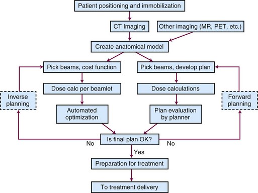
Figure 15-3 Schematic chart of the basic components of the planning process—shown for both forward and inverse planning.
Positioning and Immobilization
Basic patient positioning, including location of the arms and legs and positioning of the patient (supine, prone, or in some other more unusual position), depends mainly on two issues: (1) patient comfort and stability and (2) the beam directions that will be used. In most cases, conformal therapy plans make use of three or more beams that cross fire on the target from a number of different positions arranged around the patient, so the patient is typically positioned with both arms up (if the target is somewhere in the torso) or arms down (head and neck and brain targets). For superficial targets, the target is typically positioned facing up, but for most deep tumors, the cross-firing beam directions can be achieved with the patient in standard supine or prone positions, whichever is most stable and accurately set up. There have been studies of the benefits of various positioning decisions (e.g., prone versus supine) for patients with prostate tumors66; there is some debate about the relative merits of the possible anatomic changes that occur for the prone versus the supine position, relative to other advantages and disadvantages for planning, daily setup, and respiratory motion-related stability.
The use of various types of so-called immobilization devices to help with patient positioning and immobilization for conformal therapy has run the entire gamut of possibilities, from the use of stereotactic head frames and other such devices that are physically attached to the patient’s skull to other techniques that do not use any immobilization device. Early conformal therapy (1980s to 1990s) often incorporated a foam cradle device to help position the patient67; it is currently thought that more precision can be achieved without use of the cradle devices. In the end, each clinic should document the setup accuracy that is achieved with their chosen methods, for each clinical site, so that the planning and delivery process can take proper account of the expected systematic and random setup uncertainties. The use of in-room imaging systems (e.g., diagnostic and megavoltage CBCT) has provided more detailed information about setup accuracy, and makes it possible to improve setup accuracy and minimize margins using IGRT setup.
Computed Tomography, Magnetic Resonance Imaging, and Other Forms of Imaging
The development of x-ray CT in the 1970s and its application to radiotherapy planning18 were absolutely crucial milestones in the development of conformal therapy techniques. Without the cross-sectional anatomic imaging provided by CT (and MRI), there was not enough anatomic knowledge about the tumor or normal anatomy to consider the use of highly conformal dose distributions. Certainly, once the detailed anatomic information provided by CT became available, it was clear that radiotherapy planning and treatment should make use of this new and detailed description of the patient to better spare normal tissues and more accurately deliver dose to the tumor. Conformal therapy is a logical response to the detailed information provided by CT.
Modern conformal therapy is always based on a 3D anatomic model of the patient, which is typically based on a CT scan of the involved region. Usually, a specific type of CT scan, the treatment planning scan, is obtained for use as the basis for treatment planning. Features of the treatment planning scan are listed in Box 15-1.
Box 15-1 Treatment Planning CT Scan Features
Developments in CT and treatment delivery technology have made the consideration of motion during CT scanning (and radiotherapy treatment) an important research topic. 4DCT describes various techniques for obtaining CT data correlated with patient respiratory phase information so that the changes associated with respiration (or other motion) are displayed. For certain clinical sites (e.g., the lung, the breast), it is clear that consideration of respiratory (and, perhaps, cardiac) motion will be an important aspect of the initial imaging of the patient, so that an appropriate model (perhaps, a time-varying or 4D model) of the patient can be used for further planning and analysis. 4DCT,68 respiratory gating,69 active breathing control (ABC),70,71 or other methods are often used for many treatment sites, though which combinations of techniques and methods are most efficient and appropriate is not yet clear.
CT provides anatomic and electron density information that is critical for most treatment planning, and it also provides a geometrically accurate base for planning. However, it provides only anatomic information, not the physiologic and functional information that should be very helpful for planning, and it provides only a limited amount of soft tissue contrast. MRI can provide complementary kinds of data, including excellent soft tissue contrast and different kinds of physiologic information. In addition, functional magnetic resonance imaging (fMRI) studies can provide some of the functional information that to this point has been unavailable. Other kinds of imaging also contain complementary or new information. PET and single-photon emission computed tomography (SPECT) provide functional and physiologic information and can be quite important in helping define target volumes and regions that should be included or excluded from the radiation fields. Which modalities, scans, tracers, and analysis methods should be used for specific features is well beyond the scope of this work. However, in order to quantitatively make use of any additional imaging modality for treatment planning, one should incorporate a number of important procedures into the imaging process, as listed in Box 15-2.
Box 15-2 Imaging for Treatment Planning (Not Including CT Imaging)
Anatomy for Treatment Planning
Three-Dimensional Anatomic Model
To allow conformal therapy planning, the representation of the patient that is used for treatment planning must be realistic and three-dimensional. In general, the basic data used to define the anatomy come from a CT study, typically consisting of 50 to 200 CT scan slices. The anatomic model of the patient is based on this CT data and consists of a number of objects (structures) that delineate organs or other objects (e.g., target volumes) in 3D (or 4D; see Motion, Setup, and Four-Dimensional Anatomy). These structures can be defined by (1) a series of contours, (2) a 3D surface description, (3) a voxel-based description, or (4) a set of points distributed either randomly or on a grid. Methods used to delineate these structures are described in the section on Structure Delineation and Contouring.
Target Volume Definition and Margins
To plan and deliver conformal therapy, it is essential to accurately define the volumes that must receive high radiation doses, the “target volumes.” As described in detail in the International Commission on Radiological Units (ICRU) report ICRU-50,72 three kinds of target volumes are typically defined, as summarized in Table 15-1.
| Abbreviation | Name | Description |
|---|---|---|
| GTV | Gross tumor volume | Volume of macroscopic tumor that is visualized on imaging studies |
| CTV | Clinical target volume | Volume that should be treated to a high dose, typically incorporating both the GTV and volumes that are assumed to be at risk due to microscopic spread of the disease |
| PTV | Planning target volume | Volume that should be treated in order to ensure that the CTV is always treated, including considerations of systematic and random daily setup errors and intertreatment and intratreatment motion |
The gross target volume (GTV) is typically delineated by drawing the imaged tumor on each of the imaging studies that are available. CT is used often, but for many sites, MR and PET can be very useful. When multiple imaging studies are available, the GTV can be drawn on each study, and then, using dataset registration to geometrically align the different datasets (see Multiple Imaging Modalities: Dataset Registration and Fusion), one can transfer the different GTV contours onto a single dataset. How to combine the various GTVs defined is the subject of ongoing research; however, typically, one will combine or take the union of all the defined GTVs in order to make sure that no gross tumor is missed within the defined GTV.
Often, the PTV is designed by simply defining an isotropic margin (e.g., 1 cm), and the CTV is expanded by this margin to create the PTV (Fig. 15-4). This expansion should be performed in three dimensions because expansion of contours only in the axial plane will lead to PTVs that are not correct in the third dimension. If the uncertainties are not isotropic but are larger in one direction than in the others (e.g., due to respiration), then the margin to be applied should be anisotropic.
There has been a great deal of work studying patient positioning, motion, and target volume delineation errors, and analysis of these issues has led to specific recommendations for the size of the margin (between the CTV and the PTV) that should be used for the PTV. As described in Consideration of Setup Error and Patient Motion, one reasonable method for deciding the PTV-CTV margin has been determined to be 2.5 × Σ + 0.7 × σ, where Σ is the standard deviation of the systematic error and σ is the standard deviation of the random errors for the population of patients treated in that particular site.73 To apply this formula, it is important to have measured, for your institution and each clinical site, the two standard deviations. As can be seen from the formula, the systematic errors in the process, such as incorrect contouring or use of a nonrepresentative CT scan for target delineation, are much more important issues than random day-to-day setup errors.
Normal Tissues
Multiple Imaging Modalities: Dataset Registration and Fusion
Several issues need to be solved to make quantitative use of the additional imaging information.
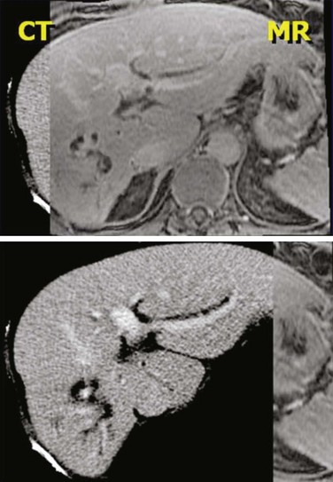
No matter what kind of registration algorithm is used, it is necessary to verify the registration and then to use the data from the various imaging studies. Verification typically consists of image-based or structure-based comparisons between the two datasets, with the goal of confirming that known structures from the two imaging studies accurately line up (Fig. 15-5). The quality of the registration depends on what parts of the images are most important clinically and must be reviewed by the planner/physician because at this point, no quantitative measure accurately takes into account all the clinical knowledge of the case. Once the registration is verified, then contours or 3D structure definitions from one dataset can be transferred into the base coordinate system for planning. This combination of data from multiple imaging sources is sometimes called image fusion.
Motion, Setup, and Four-Dimensional Anatomy
Several methods to handle motion and setup effects are in use or being investigated:
Over the next several years, a great deal of technical progress can be expected in this area.
Plan and Beam Definition
Beam Technique (Energy, Direction, and Type)
Shaping with Blocks and Multileaf Collimator
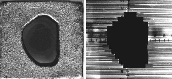
Although beam directions are important, shaping the radiation field to conform to the shape of the target volume is one of the crucial and defining concepts for “conformal therapy.” The shaping can be accomplished equally well by focused blocks or with an MLC, as illustrated in Figure 15-6. The conformal shaping of focused blocks is in fact “more conformal” than the jagged shape created by an MLC, although the MLC has a number of other advantages that have led to its popularity.
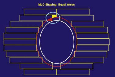
The routine use of conformally shaped fields designed during treatment planning depends in large part on the availability of the BEV display in the planning system because this view of the target shows the projection of the shape of the targets from the point of view of the radiation beam, which is what is needed to design field shaping. The simplest method used to conformally shape the fields (with either blocks or MLC) is to create a uniform geometric margin around the projection of the targets in the BEV and to set the shape to that margin, as shown in Figure 15-7. This method, the basis of the simplest type of conformal therapy, is sometimes called geometric conformation, or beam’s-eye view, targeting. Shaping a block to a given contour is easy, but with an MLC it is more complicated38: The most commonly used method is the so-called equal area method (Fig. 15-7).
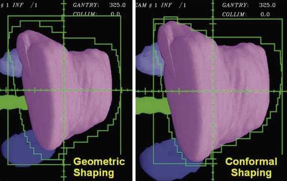
Using a uniform geometric margin for the field shaping does not lead to the most conformal dose distribution. To truly conform the dose distribution to the target, one must optimize the shaping of each of the beams so that the dose distribution is conformal. Figure 15-8 demonstrates the types of differences that occur when beam shapes are designed with a uniform margin and when the shapes are optimized to conform the dose to the target. Beam directions, the penumbra, and how the beams cross fire on the target affect the margins required for individual beam shapes.
It is possible to create intensity-modulated beams using a limited number of MLC-shaped “segments” all from the same gantry angle. This “segmental” IMRT can be created using the normal interactive planning paradigm (“forward planning”)74 or the limited number of segments can be created by an inverse planning paradigm (see, e.g., “direct aperture optimization”).75 The use of a few segments to improve target homogeneity (e.g., in the treatment of breast cancer with tangential fields) is a logical extension of the concept of wedged tangents when 3D planning is available.
Other Beam Technique Decisions
There are numerous other decisions to be made when creating the plan.
Intensity-Modulated Radiation Therapy
Soon after conformal therapy began to be used clinically in the late 1980s, Brahme,54 Bortfeld,55 and others introduced the idea of modulating the intensity across each radiation beam, assisted by computer-based optimization algorithms to help determine the intensities required of the different parts of the beam. IMRT is now commonly used to create highly conformal treatment plans.
Intensity-modulated fields can be achieved in a number of different ways. There is a continuum of situations ranging from a flat field to multiple shaped segments to a beamlet-type description created by either a series of SMLC segments or a dynamic DMLC sequence. For plan optimization strategies, there is a similar range from simple (forward) iterative planning to optimized (inverse) planning that is driven completely by a mathematical cost function. Typically, the most complex intensity distribution (IMRT) is generated with inverse planning, but it is also possible to perform optimization for flat field conformal therapy.77
Dose Calculations
Algorithms
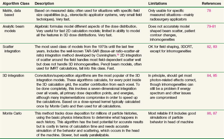
Many different types of calculation algorithms have been developed for photon and electron beams, and new improvements or implementations are continually becoming available. It is beyond the scope of this text to describe any algorithms in detail. Algorithms ranging from simple table look-ups based on measured data to Monte Carlo simulations that require many hours of central processing unit (CPU) time of the fastest computers all have their place and are the appropriate choice of algorithm for one particular situation or another. Table 15-2 summarizes some of the advantages and disadvantages of each class of photon algorithm. If there is a choice of algorithms for conformal planning, the choice should be made with careful consideration of the potential limitations of the chosen algorithm, and the radiation oncology physicist should carefully commission the algorithm for clinical use by comparison with appropriately measured data for the local machines in order to demonstrate the adequacy and limitations of the algorithm for clinical use.88
Plan Evaluation Tools
Dose Display
The most commonly used type of display of the dose distribution for a plan consists of displaying contour lines of constant dose, or “isodose lines,” on top of the anatomic information that was used for the plan. These kinds of displays have been used for many years—first with only the contours of the patient (obtained by hand measurement using solder wire or other techniques) and then later displaying the isodose lines on top of the CT scan. For conformal planning, not only axial cuts should be used for the isodose lines but also coronal and sagittal reformatted CT images, because display of isodose lines on multiple orthogonal cuts can give the planner a more 3D sense of the coverage of the target volume. 3D graphics techniques can be used to put the images and dose lines in 3D perspective, as shown in Figure 15-9. A variation of the isodose line display is the colorwash display, in which the dose level calculated for each pixel of the image is used to assign a color value (see Fig. 15-9C).
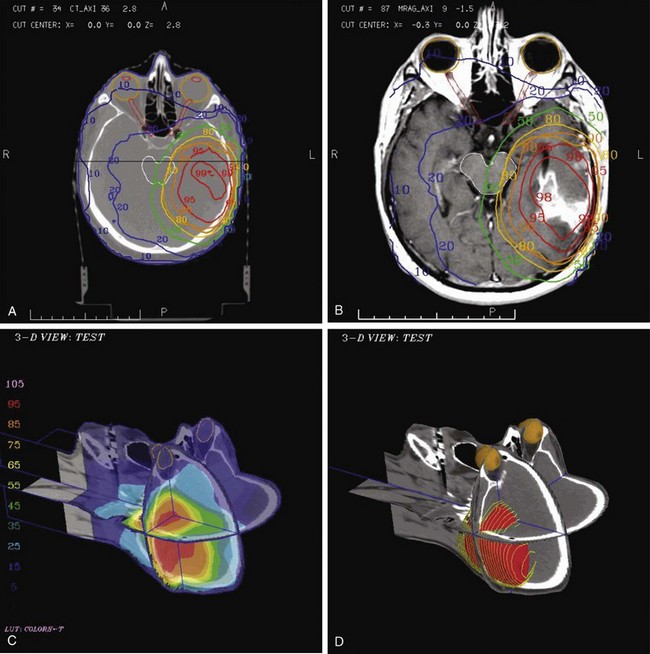
The goal of conformal therapy is typically to conform the shape of the high-dose region to the target in three dimensions, so display of the 3D dose distribution shape may be a help when evaluating the conformality of the plan. The 3D analog of an isodose line is called an isodose surface. Also, isodose surfaces, sometimes called “dose clouds,” are typically displayed in a 3D perspective graphic image (see Fig. 15-9D).
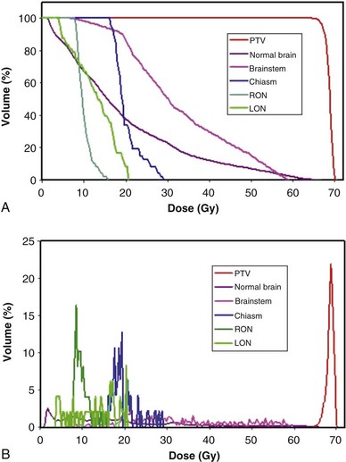
Dose-Volume Histograms
Review and evaluation of the dose throughout the patient in three dimensions can be complex and time-consuming processes, and it is also difficult to give specific guidelines for normal tissue or tumor responses with respect to that complex data. It has become standard to evaluate the dose received by the target volumes and normal tissues using DVHs. To form a DVH for any 3D object, one looks at the dose value for each voxel in the object and forms a histogram, counting the number of voxels that receive each different dose level. Because the volume of each voxel is known, the volume of the organ receiving each dose level is known. See the review by Kessler89 for more detail.
Minimum, Maximum, and Other Quantitative Metrics
DVHs are only one kind of dosimetric analysis that can be used for conformal planning, and many other kinds of analysis are possible. For example, simple dosimetric metrics are often used to help make planning decisions. The maximum dose allowed within a target volume, or inside critical organs, is often specified in conformal therapy protocols. Particularly for IMRT conformal plans, the maximum dose may be a fairly difficult metric to use clinically because it may depend strongly on the dose calculation grid spacing used and on details of the dose calculation algorithm implementation. A volume-based maximum dose criterion (e.g., the maximum dose to 1 cc of the object) is typically less sensitive to algorithmic details. Similarly, the minimum dose to the PTV is subject to the same algorithm-related limitations and may be of limited value, particularly for IMRT planning. Another common dose metric is the mean dose to a structure, often used to describe target doses and for certain volume-effect organs such as the lung and liver, where the normal tissue complication probability (NTCP) generally scales with the mean dose to the normal tissue.90
Use of Equivalent Uniform Dose (EUD) and “Biologic Models”
There are many kinds of models that have been developed for the NTCP, and these models have been applied to specific complications for many different organs. Discussion of these different models is beyond the scope of this work, and here we briefly describe only the most well known model, the Lyman NTCP model. John Lyman developed the three-parameter “Lyman” model early in the 1980s.91,92 This power law model is a phenomenologic model that characterizes complications using three parameters: TD50 for uniform irradiation, the slope of the dose sensitivity (n), and the volume parameter (m):
where

To use this model for a real clinical DVH, one typically uses the Kutcher-Burman DVH reduction method93 to convert the clinical DVH curve into a DVH with a single dose and volume, which are then used inside Equation 1. Together, these techniques are typically called the LKB (Lyman-Kutcher-Burman) model.
When developing this model, Lyman made no claim that it was a real biologic model; he simply developed the simplest model that agreed with some of the most basic behavior of NTCPs, at least as characterized at that time. The model has been used extensively, either as a way to characterize complication data or for plan evaluation and comparison. A very important starting point for study of NTCPs of various organs was published by Emami,94 who summarized a tabulation of then current knowledge of clinical complication expectations (based on a physician working group) using Lyman NTCP model parameters. Recently, complication data and parameterizations for many clinical sites have been reviewed by site-specific groups of experts in order to provide updated complication modeling information.95 The Lyman model has proven to be a useful way to parameterize clinical NTCP data and has been used as part of dose escalation studies based on treating patients with a specific isocomplication level (for liver96 and lung97).
Just as the dose-volume-effect relationship is important to know for normal tissues, it is also very important to know for the tumor. The tumor control probability (TCP) is the subject of clinical studies and modeling and is a way of comparing expected tumor responses with planned dose distributions. A number of different models exist, including the Niemierko-Goitein98 and Nahum99 TCP models. Most of these models use various basic assumptions about tumor cell density and distribution, the statistical interactions between dose and tumor cell survival, and the incorporation of population-based statistics for tumor heterogeneity, and may also consider effects that depend on tumor stage, hypoxia, and other issues. Tumor cell biology and predicting local tumor control are very complicated subjects that are well beyond the abilities of current models. TCP modeling is used in a reasonably limited way because it is known that the predictions are of limited accuracy.
The equivalent uniform dose (EUD) is often regarded (at least partially) as a biologically related parameter that is often used for treatment plan evaluation and optimization. The EUD was originally described by Niemierko100 by using a biologically and statistically influenced method to derive a dose parameter that was related to the effects one would expect on the tumor. The EUD has been generalized further101,102 to be useful for normal tissues and targets. Because the EUD is in principle a generalized mean of the dose distribution according to a specific weighting method, one may use the parameters to represent the sensitivity of the tumor to underdosing in a small region or the effect of hot spots in the tumor. Because the concept of the EUD is relatively new, numerous publications and analyses continue to explore and expand the characterization of tumor and normal tissue responses using various EUD representations.
Forward Planning
Setting Planning Goals
Iterative Planning
Shaping beams is a very important part of the iterative planning process. Typically, a BEV margin of 6 to 7 mm is a good starting point for conformal beam shaping, but the shape of each field will then need to be modified to improve the conformality of the calculated dose distribution, as discussed earlier. This is the part of the iterative forward planning process that is most time-consuming, potentially, because in principle one needs to optimize the location of each leaf of the MLC for each beam, and there often are more than 100 involved MLC leaves in each field. The changes in shape that are needed are somewhat predictable, though, because larger MLC margins are needed in regions where there are no other beams (e.g., the superior and inferior aspects of the PTV for a plan with axial-only fields), whereas the margins can be much smaller if there are other beams that are transiting from an orthogonal direction. In the end, however, many iterations of the shapes may be necessary to get reasonably close to the optimal shaping. This is the part of forward planning that is often time-limited by clinical needs, and it could potentially be significantly improved by the application of computerized optimization methods to perform this shaping automatically.77 Beam weights, use of wedges, and collimator angle rotation followed by revised beam shaping can also be part of the iterative planning process.
Inverse Planning
A typical inverse planning process can be summarized as follows:
Comparison of this process for inverse planning with the previously described forward planning process (see Forward Planning) shows that only a couple of steps are really different; most of the planning process is approximately the same. However, for inverse planning, most interactions aimed at improving the plan must be made by modifying the cost function used for the optimization, a much more indirect type of control on the plan parameters than one has when modifying a beam shape while doing forward planning.
Goals for Inverse Planning
Optimization Method
The most important issue affecting the quality of the final IMRT plan is typically the type of cost function used and, in particular, how the different parts of the cost function are defined for each relevant organ or other anatomic object. In some systems, there is very limited flexibility in the type of cost function available because the cost function is limited to a simple method (often, a quadratic function of dose) in order to allow the gradient descent-based optimization search method to easily calculate the derivative of the cost function for each variable. However, other cost function methods can be quite general, allowing the use of dose, dose-volume, biologic model, or other types of costlets that can be combined into an overall cost function.61 In any event, it is the relationship of the different costlets (individual pieces of the cost function) that determines how important the various parts of the plan evaluation are, so by changing one or more parameters in a costlet or costlets, one can drive the solution of the plan toward a different type of solution. Learning how to modify the cost function to modify the kind of solution achieved for the plan is one of the most important aspects of inverse planning and may take a significant amount of effort to master.
A number of different types of search algorithms are used for IMRT optimization, and these different methods can have some specific characteristics that are useful to know. Many current inverse planning systems, however, make use of only one search method, so many planners will not be able to choose different methods for specific patients or plans. Many inverse planning systems use gradient descent-based search methods because they are fast, but this forces their cost functions to be limited to easily differentiable functions, typically quadratic dose penalties with a form such as wi(D − Di)2, where wi is the weight of the penalty and Di is the dosimetric goal for the ith object. This type of cost function tends to lead to tails on the DVHs because a small volume of the object can go higher than the desired dose without causing too much of a penalty. Another common concern about gradient-descent algorithms is the possibility of local minima in the cost function. For simple cost functions this is not a problem, but use of many costlets or complex functions can potentially lead to local minima that may trap the optimization search at a solution that is not the “global” minimum (the optimal solution). To avoid the possibility of being trapped in such local minima, stochastic search algorithms such as simulated annealing52 and others can be used. These algorithms can perform a global search that is more certain to achieve the global minimum of the cost function, but they often are quite slow and can also be sensitive to the search parameters used (as in fact are all of the search algorithms).
Plan Preparation
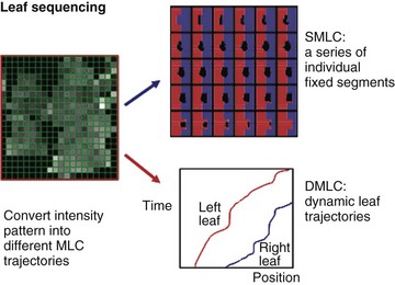
MLC Leaf Sequencing
Several different methods of IMRT delivery make use of MLC systems (Fig. 15-11). SMLC, or segmental MLC, uses a set of fixed MLC segment shapes to deliver the intensity pattern, with the beam off as the MLC moves from one shape to the next. Many algorithms have been developed for this kind of MLC sequencing.45,105 DMLC (dynamic MLC) uses MLC leaves that move on a trajectory that is defined so that the desired intensity pattern is created. Typically, a “sliding window” algorithm is used to derive the trajectories required.47 Volumetric modulated arc therapy (VMAT) is a relatively new IMRT method that combines rotational (or arc) delivery and MLC-based IMRT.59,60 Development of more efficient or effective algorithms or methods and characterization of the details of the differences between the various methods already in use are areas of active research. It appears that no one method or system is clearly better than the others, although there can be specific advantages or disadvantages for particular treatment types that are associated with a particular sequencing or delivery method.
Conformal Therapy Delivery
Patient Setup and Localization
One of the most crucial aspects of patient treatment involves the setup and localization of the patient for each treatment fraction. For many years, this process has typically involved lining the patient up to laser lines using skin marks defining lateral and anteroposterior (AP) projections of the plan isocenter. To verify correct patient positioning, lateral and AP localization films were obtained (typically, once per week) to confirm the correct placement of the isocenter inside the patient. The “orthogonal pair” films were compared by eye with the expected location (shown by DRR or BEV display from treatment planning) to document the accuracy of the setup. Use of a calibrated gradicule in the accelerator head when making the megavoltage images106 was very helpful in making the comparison somewhat quantitative.
In the last several years, many new developments have begun to change the setup and localization process to allow much more quantitative and automated setup procedures. The development and implementation of electronic portal imaging devices (EPIDs)107 for megavoltage imaging, diagnostic x-ray imagers,108 and megavoltage or diagnostic CBCT scanning65 using accelerator-based systems have revolutionized the setup and localization process. If the new digital imaging capabilities are integrated with the computer-control system of the treatment accelerator, it is possible to perform relatively automated patient setup with accuracy much improved over the old manual method.109 Over the next years, it is clear that integration of cone beam imaging into the treatment localization and setup process will lead to significantly improved accuracy for routine patient setup.
Manual and Computer-Controlled Treatment
Since the 1990s, integrated computer-controlled systems have entered widespread use for control of the treatment process, usually tied to a treatment plan or information system database that contains all the treatment plan information. To varying degrees, the progression through the setup process and treatment delivery is often automated, controlled via the machine’s system. However, much remains to be done to optimize the efficiency, safety, and accuracy of the computer-controlled treatment delivery process. There has been some published work on the treatment delivery process,104,110–112 but too often a treatment process taken directly from the old manual techniques is implemented with the computer-controlled system, without attention to changes needed for accuracy, safety, or efficiency. As the patient setup process, along with CBCT or localization imaging using integrated electronic imaging systems, is integrated into the computer-controlled treatment process, additional effort to optimize the process will be required. Much work is needed in this area.
The use of IMRT treatment delivery has also caused a dramatic change in aspects of the delivery process. With simple nonconformal fields, it was common to outline the shape of each treatment field on the patient’s skin and to confirm at treatment that the shape and placement of each radiation field agreed with the shape drawn on the skin. This limited very large errors but certainly was not a highly accurate positioning check. With modern IMRT treatment fields, understanding the fluence pattern that will be delivered requires computer-generated images, and there is no intuitive way to check the field shape, position, or intensity pattern directly on the patient, so more sophisticated QA checks or procedures are necessary. With modern EPID systems, so-called portal dose measurements (intensity or “dose” measured with the EPID) can be compared with that which is expected, and used as a QA check that can potentially identify both geometric and dosimetric differences between the desired and delivered dose distributions.113,114 It is also possible to reconstruct the delivered intensity distribution by analysis of MLC trajectory information.115 The further development of quantitative online delivery QA checks along with their integration into the treatment delivery process is an area of significant ongoing experience that is expected to lead to much more sophisticated delivery systems.
Patient Treatment Chart
It is incumbent on all users of such new electronic chart systems to carefully implement and use the new technology. It is not appropriate to just convert all the old paper-based documentation practices into electronic forms, as some standard paper-based methods just do not work well in the electronic world, such as writing notes in a chart in pencil to show what should happen in some number of future treatments. Some analysis of the needs for electronic treatment charts has been published,112 but the ongoing transition from paper to electronic charts should be evaluated and performed with care. Complex IMRT-based prescriptions and plans probably require new methods that were not supportable in a paper-based chart, and users of highly sophisticated conformal therapy will have to develop their own migration from paper to electronic prescriptions and treatment charts.
Consideration of Setup Error and Patient Motion
For many years, the ICRU-50 concept of the PTV72 has been the sole response to these issues. However, the desire to perform precise conformal therapy has led many institutions to study these issues in more detail and to measure the uncertainties associated with these different issues.
The importance of correcting the systematic setup uncertainty, if possible, has also led many institutions to convert their positioning verification procedure from the use of weekly port films, with position correction if a large-enough error is seen, to a more sophisticated offline or online repositioning scheme, and to more sophisticated setup, localization, and imaging strategies that are now called image-guided radiation therapy (IGRT). Use of daily IGRT setup correction based on imaging (either megavoltage imaging, kilovoltage imaging using an integrated kilovoltage tube and imager, or kilovoltage or megavoltage CBCT) is the most accurate method for daily patient positioning, although these IGRT techniques require more effort. Even relatively straightforward daily imaging techniques using EPID imaging and automated repositioning of the treatment table demonstrate large improvements in setup accuracy (e.g., improvement in Σ from >8 mm to 2.3 mm for liver patients).116 It is also possible to apply “decision rule” protocols117,118 in an offline manner: Verification imaging is performed several days in a row, and only after the systematic error in the setup is determined is a correction made. Daily IGRT also provides detailed information about the stability of patients and their positioning, and can make possible adaptive treatment changes that can allow individualization of the margins and setup techniques used for individual patients. This is a rapidly developing area, and promises improvements in patient treatment precision, as well as in improving our ability to image119 and respond to changes in the patient, tumor, or normal tissue behavior through the course of therapy.
Clinical Considerations
Immobilization, Setup Uncertainties, and Patient and Organ Motion
Patient positioning and immobilization should be comfortable but minimize motion and setup uncertainties. The clinically measured range of motion and setup uncertainties for each clinical site should be known, as they will determine the margins required for the PTVs (and planning organ at risk volume [PRVs], if used). Additional margin information can be obtained from the literature, as margins for a sample of patient populations using commercial, widely available immobilization systems have been determined and published; for example, the setup error standard deviation when using a commercial thermoplastic mask for head and neck immobilization has been determined to be 3 to 4 mm if patient-specific information is obtained and daily patient repositioning protocols using portal imaging are enacted.120 Although weekly verification is considered the standard method for conventional radiation therapy and 3D radiation therapy, daily imaging of the skeletal anatomy or implanted fiducial markers using an EPID has reduced systematic and random variations.
The systematic setup error can be established from imaging during the first three to five treatments121 and can then be corrected, leaving only the random deviation to be accounted for by adequate PTV margins. Daily patient imaging and correction of setup deviations can reduce it even further, making it possible to reduce the PTV margin further, thereby increasing the sparing of adjacent noninvolved tissue. Individual measurements of motion and setup uncertainties, and their corrections, are especially important in sites where breathing or internal motion is significant. Techniques for dealing with this motion include active breath hold or gating for respiratory motion,69,122 beam tracking of moving targets,123 or fiducial markers for correction of prostate movement due to rectal filling–related changes in target position.124
Considerations of patient setup and immobilization approaches are complex. For example, in prostate cancer, prone patient position improves the separation between the prostate and the rectum compared with supine position,125 thus potentially improving sparing of the rectum. However, prone positioning also increases breathing-related motion of the prostate.126 In head and neck cancer, immobilization of the shoulders is essential if targets in the low neck are included in the conformal plan but is not required if the low neck is treated with an anterior field matched with the IMRT plan for the high neck.
Determining the Targets
The dosimetric advantages of IMRT need to be balanced with potential pitfalls related to the production of tight dose distributions around targets outlined on the CT scan. The most important issues are the reliability and reproducibility of outlining the targets that typically rely on a single planning scan performed prior to the start of treatment. The GTV is outlined on the treatment planning CT scan using clinical and radiologic information. In many cases, contrast-enhanced CT combined with clinical information derived from physical examination is the main modality used for the delineation of the targets. For some sites, CT is not the best imaging modality for the definition of the extent of the macroscopic tumor, and ancillary studies such as MRI or fluorodeoxyglucose (FDG)-PET may add important information. MRI can be limited by its sensitivity to artifacts, difficulty in interpretation, long examination time, and cost. FDG-PET is often limited by a lack of specificity regarding tumor versus inflammation, and by uncertainties in interpretation, which may be subjective and differ depending on the observer’s experience. PET-defined target volumes can also depend substantially on the standardized uptake value (SUV) chosen to contour the PET scan. The best added information from these studies is derived following their registration either with diagnostic CT or with the planning CT scans. Rigid body geometric registration of multiple scan types can now be performed in many cases using commercially available software, whereas registration of nonrigid structures such as the rectum or bladder is the subject of ongoing research.127
Future improvements in the anatomic and metabolic imaging of tumors are expected to decrease the uncertainties in outlining the GTV to determine the volume to receive high radiation dose. However, the definition and outlining of the tissue volumes at risk of harboring subclinical disease (CTVs) depend on clinical judgment alone. It is not surprising that large interobserver differences have been noted in outlining these volumes.128,129 The uncertainties in outlining the target volumes raise concerns about the potential of highly conformal radiotherapy to miss disease while striving to spare organs adjacent to the targets. Efforts to define the volumes at risk for subclinical disease for each tumor site have been made for head and neck cancer,130,131 breast cancer,132 and cancer at other sites.133 They constitute the initial steps in this direction. Clinical validation, based on data regarding the sites of locoregional tumor recurrence and their relationships to the targets, is necessary. To date, relevant data are scant. They suggest that when target outlining is performed by experienced investigators, the large majority of the locoregional tumor recurrences are in-field, and only few marginal failures are observed.134,135,136 Until more data are available, target outlining should be done in a conservative manner. Target volume definition requires thorough knowledge and understanding by the radiation oncologist of the anatomy and the locoregional tumor spread pattern.
Head and Neck Cancer
Gross Tumor Volume
Most head and neck target volumes are defined using CT information. However, MRI is a necessary adjunct to CT for tumors close to the base of skull (i.e., nasopharyngeal and paranasal sinus cancer), where it provides better details of tumor extension and better details of the parapharyngeal and retropharyngeal spaces, compared with CT.137 MRI is essential for delineating the targets in these cases. FDG-PET, in most cases, defines smaller primary targets compared with CT, and the volumes depicted by each modality do not completely overlap.138 Relying on FDG-PET may result in changes in the outlining of the GTVs compared with outlining based on CT, at least in some patients.139 Whether FDG-PET is more accurate than CT in delineating the primary tumor GTV has not yet been established, due to the paucity of data correlating the imaged extent of the gross tumor and its size in pathologic specimens following resection. Current data from series involving imaging followed with surgical validation suggest slightly more accurate definition of the gross tumor by FDG-PET compared with CT. In the delineation of neck lymph node metastases, FDG-PET has a higher sensitivity than CT.139,140 Until more data are available, the most prudent practice seems to be outlining the GTV as the composite of the lesions observed on CT and PET. It should be emphasized that FDG-PET has poor sensitivity for occult disease (25% in the clinically negative neck141) and cannot be relied on to determine the CTV. In cases of recurrent cancer, where extensive scars from previous surgeries confound the CT-based delineation of the tumor, FDG-PET has a clear advantage142 and should be used as the primary modality for the delineation of the GTV.
Clinical Target Volume
The CTVs for head and neck cancer include subclinical disease in the vicinity of the primary tumor and lymph node groups at risk of subclinical disease. Outlining the CTVs requires knowledge of the natural history and pattern of failure of each tumor site. Suggestions for the selection and delineation of the targets have been published,130,131,143–146 and atlases detail the recommended delineation of various lymph nodal groups. Studies detailing tumor failure patterns and how these patterns can affect modification of target outlining rules are emerging.134,136
Lung Cancer
Gross Tumor Volume
In lung cancer, the primary lesion should be contoured on the CT scan using window/level settings for pulmonary visualization (i.e., a pulmonary window). FDG-PET adds significantly to the staging information gained from CT regarding the tumor extent and is an essential tool for the delineation of the GTV, with significantly better accuracy gained by fused PET-CT compared with each modality performed separately.147 This is particularly helpful when an FDG-PET avid but anatomically indistinct tumor is present. PET can differentiate atelectasis from tumor, preventing unnecessary inclusion of noninvolved lung tissue in the GTV.148 In the free-breathing patient, FDG-PET depicts the tumor extent in both expiration and inspiration, providing information about breathing-related tumor motion and position changes that is not gained from the fast CT. FDG-PET is expected to improve significantly the outlining of the GTV for radiation therapy purposes.149
Clinical Tumor Volume
The CTV for the primary tumor requires 6- and 9-mm expansions for squamous cell carcinoma and adenocarcinoma, respectively, according to histopathologic studies.150,151 Outlining mediastinal lymph nodes at risk of harboring subclinical disease may be performed using the surgical definition of the mediastinal nodes and an atlas describing their positions for radiotherapy planning purposes.152 Some centers (University of Michigan153 and Memorial Sloan-Kettering Cancer Center154) do not define mediastinal nodal CTVs and do not intend to irradiate lymph nodes at risk without evidence of involvement, due to the pattern of locoregional failures in these patients that is predominantly within the GTVs.
Because respiratory motion can significantly affect the dose distribution, lung target volumes often require use of an internal target volume-like margin (from ICRU-62155) for respiratory motion of the target, depending on whether measures to reduce the motion are used (e.g., ABC or gating). In the absence of such measures, large variability in tumor motion is observed among patients, on average 1 cm in different directions. However, the variability among patients is extensive and requires individual measurements.156 Advanced image-guided systems, including CBCT and tomotherapy, can visualize the tumor and organs at risk in three dimensions prior to treatment that allows for online correction. This strategy is especially useful in treating early-stage lung cancer patients with stereotactic body radiation.
Brain Cancer
Gross Tumor Volume
The GTV is defined using MRI with and without contrast and then registered with the planning CT. MR T1-weighted images with contrast show contrast-enhancing tumors such as meningioma and glioblastoma. T2-weighted images show edema that is likely to contain microscopic tumor in cases of high-grade glioma. T1-weighted fluid-attenuated inversion recovery (FLAIR) images can differentiate brain infiltrated by tumor from edema caused by a mass effect and may enhance the definition of nonenhancing tumors.157
Clinical Tumor Volume
Lacking well-defined anatomic compartments, the CTV for a brain tumor typically consists of a uniform expansion of the GTV by 1 to 2 cm depending on tumor grade. At the University of Michigan, dose-escalation studies have aimed at increasing the dose to the GTV alone, whereas the CTV dose remained constant in order to limit brain volume receiving a high dose.158
Gastrointestinal Cancer
Many clinical trials in conformal radiotherapy in gastrointestinal cancer have been performed in pancreatic cancer, in which tumor control rates are poor and 3DCRT and IMRT may reduce the volume of small bowel and duodenum irradiated, potentially allowing higher radiation doses.159 Outlining the targets must take into account significant respiratory-related organ motion, ranging up to 25 mm in various directions.160 Without methods to reduce respiratory movement, the large PTV margins required to accommodate this motion are expected to increase markedly the volumes of the small bowel and duodenum receiving target doses and limit the ability to escalate tumor dose. Highly conformal radiation techniques also show significant acute toxicity benefit in the treatment of anal cancer. To assist with target delineation, CTV guidelines have been proposed by the RTOG consensus panel for anal cancer treatment.161
Prostate Cancer
The gross disease within the prostate gland cannot accurately be defined using conventional imaging, and routine practice is to outline the CTVs. Research in magnetic resonance spectroscopy (MRS) suggests that it may be used to identify tumor cell foci within the prostate using the choline-to-citrate ratio, which is higher in tumor cells compared with prostatic cells.162 If confirmed, MRS imaging may be used to define the GTV, or the boost volume, within the prostate.163 The prostate’s superior margins at the base of the bladder and its inferior margin (apex) are better defined on MRI compared with CT. MRI is also better at defining the rectal and bladder boundaries and the penile bulb. Prostatic motion is on average 5 mm in both anterior-posterior and superior-inferior directions. If adjustments for this motion are not made, 1-cm margins are required to take into account motion and setup uncertainties. The PTV is typically defined using these margins around the prostate alone in patients with a promising prognosis; around the prostate and seminal vesicles in intermediate-risk and high-risk patients; and including the pelvic nodes in high-risk patients. Some centers limit the margin posteriorly at the interface with the rectum to 0.6 cm.164 High-risk patients and select adjuvant/salvage basis are considered for postoperative bed and/or pelvic IMRT to decrease gastrointestinal and genitourinary complications, In cases of pelvic IMRT, a nodal CTV is generated using a 7-mm margin around the iliac vessels with sparing of the bowel, bladder, and bony structures.
Gynecologic Cancer
Accurate target delineation is vital in the conformal radiation treatment of cervical cancer. MRI defines gross abdominal disease better than CT and is strongly recommended in defining the tumor volume, which may be further aided by FDG-PET.165 Fusion of the T2-weighted MRI images to the simulation planning CT scan is advised when possible. To assist in delineating targets, the RTOG consensus panel has proposed guidelines.166 In brief, the CTV should include the GTV, remaining cervix, uterus, parametria, ovaries, and vaginal tissues. The nodal CTV must include involved nodes and the draining nodal groups, including the common iliac, external iliac, and internal iliac nodes as well as the obturator and presacral nodes. Inclusion of the para-aortic lymph nodes is based on the extent of disease and results of staging investigations. In defining the nodal volumes, most clinical studies outlined along blood vessels with margins of 0.5 to 1.5 cm.167 Due to substantial organ motion, tumor regression, and deformation associated with cervical cancer patients, margins of 1.5 to 2 cm around the CTV are recommended for the primary PTV with a PTV margin of 7 mm around the nodal CTV. Whether IMRT can be useful in the treatment of an intact cervix, replacing brachytherapy or, more likely, serving to augment GTV doses after brachytherapy, is not yet known. If IMRT is considered for the intact cervix, daily soft tissue image-guided verification is required to avoid the risk of geographic miss.
Breast Cancer
Some work on breast cancer treatment has used targets obtained by outlining the whole breast or chest wall while trying to reproduce the tissue volume that would have been irradiated with standard tangential fields, although this target is not really based on anatomy but on the older type of treatment. In order to achieve such a reproduction, marking the borders of clinical tangential fields by radiopaque wires such that they are apparent on the planning CT ensures inclusion of all tissue irradiated traditionally. There have been some efforts to define anatomic target volumes.168,169 For boost planning, the lumpectomy scar is outlined as the CTV and a 1-cm margin is assigned as the PTV, for breathing motion and setup uncertainties. When regional lymph nodes require irradiation, treatment complexity is higher, and heart volumes in left-sided breast cancer therapy may be substantial. For the outlining of the lymphatic CTVs, particularly the supraclavicular lymphatics, some anatomic guidelines have been published.132,170
Accelerated partial breast irradiation (APBI) is increasingly being used to treat early-stage breast cancer patients. The optimal margin of tissue requiring radiation after lumpectomy in patients treated with APBI remains somewhat controversial. However, contemporary radiographic and pathologic data suggest that a margin of 10 mm around the tumor bed appears adequate to cover any disease remaining in the breast after lumpectomy in most (>90%) of patients, provided the final margins are negative.171 The CTV is then limited to 5 mm from the skin surface and lung chest-wall interface. The CTV is further expanded by 1 cm to create the PTV.172
Treatment Goals and Rationale for Highly Conformal Radiotherapy
Head and Neck Cancer
Delivery of the prescribed dose to the targets in advanced head and neck cancer is often limited by the dose to the spinal cord and brainstem, especially in advanced nasopharyngeal cancer, posterior pharyngeal wall cancer, and thyroid cancer. Also, irradiation of gross disease in the posterior neck may be suboptimal due to dosimetric deficiencies due to the off-cord photon and posterior neck electron beams. By making possible concave dose distributions, IMRT can overcome these deficiencies and potentially improve tumor control rates. Dose escalation to the GTVs173 or to hypoxic subvolumes within the GTV174 using IMRT has been proposed.
Sparing of the parotid glands, in an effort to reduce xerostomia, has been a major goal of earlier 3DCRT175 and subsequent IMRT studies.103,176–178 Randomized studies of IMRT versus 2D radiation therapy in nasopharyngeal cancers demonstrated improvement in salivary production179,180,181 and in observer- and patient-reported xerostomia.180 Sparing the contralateral submandibular gland in cases where contralateral level IB is not a target has been proposed, suggesting a mean dose of less than 39 Gy as a goal.182 However, IMRT cannot substantially preserve the function of the submandibular glands in some cases because these glands lie anterior to the subdigastric nodes that are important targets in both sides of the neck, and this poses a limitation on reducing xerostomia by IMRT. Similarly, reducing the doses to the noninvolved oral cavity, striving to spare the minor salivary glands183 and to reduce mucositis, is an important planning goal. Additional objectives include reduced doses to the optic pathways and inner ears in patients treated for advanced nasopharyngeal and paranasal sinus cancer,178,184,185 to the skin,186 to the carotid arteries in cases of stage T1 to T2 glottic laryngeal cancers in patients for whom treatment of regional lymph nodes is not planned,187 and to the swallowing structures damage to which following intensive chemoirradiation may cause dysphagia and aspiration.188
Brain Cancer
Dose escalation trials attempting to increase the currently poor local control of high-grade gliomas have been conducted at the University of Michigan.158 These trials used 3DCRT or IMRT delivering a high dose to the GTV while keeping a constant dose to the CTV and limiting the doses to the optic pathways and noninvolved brain. IMRT may be superior to 3DCRT in some cases in tumors that are close to the optic nerves or chiasm.
Lung Cancer
Facing low locoregional tumor control, the goals of conformal irradiation are to improve target irradiation while reducing lung volumes receiving a high dose. Using 3DCRT, trials of dose escalation have been conducted using various constraints on uninvolved lung doses, such as the mean dose, the effective dose (Veff), or the lung volume receiving more than 20 Gy (V20).189 These constraints require that only grossly involved lymph nodes be included in the targets because inclusion of nodes at risk but without evidence of involvement increases significantly the lung volumes treated to high doses.154 Using similar dose constraints, IMRT has been used to treat lung cancer.190 However, substantial geometric uncertainties about beamlet doses in lung tissue may influence the accuracy of imaging, treatment planning, and delivery. To improve the optimization of IMRT beam direction, the role of ventilation perfusion scans is being explored so that well-ventilated lung may be more appropriately spared.191 To this point, the clinical use of IMRT for lung cancer remains relatively restricted by respiratory motion and by uncertainties about beamlet doses in lung tissue.192
Breast Cancer
IMRT can produce more homogeneous doses to the intact breast compared with lateral tangential beams, potentially improving cosmetic results. In addition, IMRT may help reduce dose to lung and heart during therapy for left-sided breast cancer, especially in patients requiring comprehensive breast and nodal irradiation.193 However, it has been argued that similar improvements in breast dosimetry can also be achieved with advanced forward planned 3DCRT.
The use of partial breast irradiation is a recent strategy for the treatment of early-stage breast cancer. The main advantages of this technique include shortened overall treatment time, better access and compliance, as well as potential reductions in normal tissue complications due to reductions in treatment volumes. This accelerated hypofractionated irradiation regimen to the lumpectomy site takes into account the pattern of breast relapse that predominates in the original tumor quadrant and the assumption that good cosmetic outcome may be achieved if high fraction doses are delivered to limited breast volumes using IMRT. 3DCRT APBI has been delivered using three to five noncoplanar photon beams with a planning goal to treat 90% of the planning target with at least 90% of the prescribed dose while ensuring that less than half the breast gets 50% of the prescription dose.194
Prostate Cancer
Dose escalation to the prostate125,195,196,197 and concomitant delivery of a high dose to the intraprostatic gross tumor defined by various imaging modalities described above, while limiting the doses to the rectum and bladder to reduce the main toxicities of therapy, have been the major goals of 3DCRT and IMRT. Efforts have been reported to reduce the doses to the penile bulb198 or pudendal arteries199 to reduce the rates of treatment-related erectile dysfunction. In high-risk prostate cancer patients, when IMRT is used to treat the pelvis along with the prostate and seminal vesicles, the main purpose is to decrease the dose to the small bowel while maintaining lower doses to the bladder and rectum as above.
Gastrointestinal Cancer
Pancreatic cancer has high rates of local and distant failure despite aggressive surgical resection. In an attempt to improve this dismal prognosis, the main goal of highly conformal therapy is to treat with smaller radiation fields to allow dose escalation and more aggressive chemotherapy.200 In contrast, anal cancer patients treated with definitive chemoradiotherapy have much higher cure rates. The aim of IMRT in this setting is primarily to avoid treatment breaks by reducing acute dermatologic, hematologic, and gastrointestinal toxicity.
Gynecologic Cancer
Most current studies of IMRT for gynecologic cancer aim at reducing the volume of small bowel irradiated during postoperative treatment.201 Escalating the dose to the GTV using IMRT as a replacement for brachytherapy has been proposed,202 but it is unlikely that escalated external beam doses can match the extremely high doses delivered safely by implants to tumor in the vicinity of the implant sources. To improve hematologic toxicity, an interesting concept of bone marrow sparing using IMRT in conjunction with bone marrow imaging has been proposed by Mundt.203,204
Pediatric Tumors
The rationale for highly conformal radiotherapy in pediatric tumors is to limit the high-dose volumes in growing organs, especially bones. Although IMRT may achieve this goal better than 3D radiation therapy in some cases,205 it increases the volumes receiving low-dose radiation and the potential for future radiation-related cancers. This should be an important consideration. Only when an obvious benefit is expected should IMRT rather than simpler techniques be used in children. For example, in medulloblastoma, IMRT can reduce the dose delivered to the cochlea when a posterior fossa boost is planned with IMRT compared with parallel-opposed beams, but similar benefit may be gained by the use of 3DCRT.206
Target and Organ Prescription: Dose Constraints
Standard 2D radiotherapy has typically been delivered in two or three phases. For a typical head and neck example, in the first phase radiation is delivered to all targets, including nodal and high-risk volumes. After a dose that is likely to eradicate subclinical disease is delivered (typically, 46 to 50 Gy), additional irradiation is delivered only to the high-risk targets, to a total of approximately 70 Gy. In this scheme, all of the targets receive the same daily dose of 1.8 to 2 Gy. In contrast, with IMRT, the most commonly used plan is a single treatment plan that improves dose conformity compared with sequentially optimized plans.207 In this single integrated boost (SIB) technique, the high-risk targets receive both a higher total dose and a higher daily dose compared with the lower-risk targets, and compared with critical normal structures whose total maximal dose is constrained at total doses that are lower than the prescribed target doses. Smaller daily doses reduce the biologic effect of the doses delivered to the critical organs (normalized total dose [NTD]), so the SIB technique creates the situation in which the maximum critical organ doses usually allowed in standard radiotherapy become much more conservative when used within the SIB IMRT technique. In addition, the maximum doses specified in IMRT or 3DCRT are delivered to smaller (or much smaller) organ volumes compared with conventional radiotherapy. IMRT or highly conformal 3DCRT treatments may be safer than corresponding standard radiotherapy treatments even if nominal maximum critical organ doses are similar. On the other hand, higher-than-standard total target doses, delivered inadvertently due to nonuniform dose distributions typical of many IMRT plans, or due to intentional GTV dose escalation in an effort to increase tumor control rates,183,208 are associated with increased daily doses, causing a further increase of the NTD. This has the potential to increase toxicity related to tissue embedded within the target. Such toxicity may be apparent long after therapy and its prevalence is not yet known. Dose escalation relying on the ability of IMRT to restrict the high-dose volume to the GTVs should be conducted only within careful clinical trials.
When Should the Use of Highly Conformal Radiotherapy/Intensity-Modulated Radiation Therapy Be Considered?
Planning, delivery, and QA of 3DCRT/IMRT are more complex, costly, and work-intensive compared with these factors for previous technologies. The use of 3DCRT/IMRT is justified if it offers apparent clinical advantages. The advantage in the dose distributions achieved by IMRT compared with 3D radiation therapy is mainly in the ability to form concave, horseshoe-like dose distributions. Such distributions are desirable in cases in which the target partly encircles a critical involved structure whose tolerance is less than the desired target dose. This includes head and neck cancer cases in which the targets are arranged anterior and lateral to the spinal cord and are bounded laterally by the major salivary glands; in prostate cancer, in which the rectum invaginates into the prostate target; in lung cancer, in which the target (usually, the mediastinal lymph nodes) may lay close to the esophagus; in esophageal cancer, in which sparing the lungs from high doses is an objective; in gynecologic cancer, in which the lymph node targets are arranged lateral to and posterior to the small bowel; in left-sided breast cancer, in which the target is concave anterior to part of the lung and heart; in brain tumors near the optic pathways; in medulloblastoma, in which the posterior fossa partly surrounds the inner ear; and in others. IMRT may also be indicated in cases in which minimizing the extent of the tissues receiving a high dose (at the expense of higher volumes receiving low doses) is likely to be beneficial, such as re-treatment of recurrent cancer.209 On the other hand, it is less likely that a dosimetric benefit will be gained from IMRT in cases in which tumors are remote from sensitive tissues or are adjacent to a sensitive tissue but do not (partly) surround it, compared with simpler conformal techniques. An example of a case where the dosimetric differences between 3DCRT and IMRT are small is prostate cancer, where the anterior wall of the rectum invaginates somewhat into the posterior prostatic target. Even these small differences may be translated into a clinically meaningful benefit in reducing rectal complications by IMRT compared with 3DCRT.164
Patient-related issues include the ability to tolerate treatment times that are longer than those required for less complex treatments. Poor immobilization and breathing-related motion increase uncertainties regarding the accurate positions of the targets and adjacent normal tissue in the chest and abdomen and, to a lesser degree, in the pelvis. Daily changes in the shapes of organs such as the rectum and bladder may affect their spatial relationships with the prostate target. Due to the tight dose distributions produced by 3DCRT and IMRT, these uncertainties require the use of techniques that minimize, or take into account, target and organ at risk (OAR) internal motion in most sites apart from the brain and head and neck. An additional concern is tumor shrinkage during therapy, which may also change the shape and relative position of adjacent organs.210 Whether these changes over the course of treatment require modifications of the treatment plans in most patients is the subject of current investigations.211
The high flexibility in creating desired dose distributions by IMRT provides the ability to deliver high doses to part of tumors judged to be at higher risk than other parts. Clinical accomplishment of this concept, termed “dose sculpting,”212 depends on the verification of the utility of innovative imaging of tumor physiology and early tumor response prediction.213
IMRT treatment plans are often characterized by nonhomogeneous dose distributions in the targets that produce “hot spots,” such as target volumes receiving substantially more than the prescribed dose. This characteristic has been credited with a high rate of tumor control in nasopharyngeal cancer.178 The potential for increased local toxicity due to “hot spots” is not yet clear and may depend on the site irradiated: Very high doses delivered to the nasopharynx may be well tolerated, as attested by the common use of intracavitary boost with radioactive sources for nasopharyngeal cancer, but may not be well tolerated by the mucosa in other sites in the head and neck. In any case, heterogeneous dose distributions by IMRT are not a necessity, because relatively homogeneous doses can be obtained. The decision of whether to deliver homogeneous dose belongs to the planner.103
Potentially Negative Aspects of Intensity-Modulated Radiation Therapy
Several potential negative aspects of IMRT exist, for which there is as yet no clinical validation. Although IMRT reduces the tissue volumes receiving high doses, larger tissue volumes receive low doses compared with standard radiation therapy or 3DCRT. This is due primarily to use of many beams (often), many MUs, and leakage through the MLC leaves. This characteristic may increase the risk of radiation therapy–related malignant disease because the risk of radiation therapy–related mutations and carcinogenesis increases at intermediate rather than at high doses.214 This risk is especially relevant for young patients. As the risk of radiation therapy–related cancers increases over time, usually past 5 to 10 years after therapy, clinical data are not available at this time.
Another theoretical concern is the loss of biologic effect of radiation therapy when treatment delivery time is prolonged.215 Prolonged treatment delivery time is characteristic of some IMRT delivery techniques. There are differences in IMRT delivery modes that make a difference in this respect. For example, tomotherapy delivers sequential treatment throughout the target volumes, so that the exposure time of each tumor cell to daily radiation is short. In contrast, other systems irradiate all the targets simultaneously over a relatively prolonged daily treatment time. Whether the prolonged fraction delivery time translates into a clinical difference is not known.
Intensity-Modulated Radiation Therapy Clinical Results
Head and Neck Cancer
Interpretation of the tumor control results of many of the clinical IMRT series reported to date is limited because they are very heterogeneous regarding tumor sites and stages, have relatively small patient numbers or patient selection factors, and are characterized by relatively short follow-up periods.134,135,136,178 These factors prevent meaningful direct comparisons of tumor control rates with similar patient series treated with standard radiation therapy. These series reported locoregional tumor control rates ranging between 81% and 97%. These rates seem to be better than those of most series of standard radiation therapy for similar tumors, suggesting that there may be no compromise in tumor control rates following IMRT. However, the recent emergence of human papillomavirus (HPV)-associated oropharyngeal cancer, associated with a better prognosis compared with smoking-related oropharyngeal cancers, may contribute to the high rates of tumor control in the IMRT series, which have been conducted at about the same time that HPV-associated oropharyngeal cancers have emerged. Multi-institutional prospective noncontrolled phase II studies of IMRT in nasopharyngeal216 and early oropharyngeal217 cancers conducted by the Radiation Therapy Oncology Group (RTOG) demonstrated high rates of locoregional tumor control and suggested that centralized QA can be successfully employed in the community, assuring a high compliance with strict IMRT specifications. Few small randomized studies of IMRT versus 2D radiation therapy or 3D radiation therapy for nasopharyngeal180,218 and other head and neck cancers181 demonstrated no significant differences in locoregional tumor control rates.
Most head and neck IMRT studies use fractionation schemes that strive to mimic those used in standard radiation therapy: total GTV doses of 70 to 73 Gy at 2 Gy/fraction and high-risk nodal volume (CTV) doses of 64 to 56 Gy at 1.8 to 1.6 Gy/fraction, all in 35 fractions.176,178 For advanced tumors, these schemes should be delivered concurrently with chemotherapy. For early oropharyngeal cancer, the Radiation Therapy Oncology Group (RTOG) conducted a phase II study in which the GTV, high-risk CTV (subclinical disease surrounding the GTV and first echelon nodes), and low-risk CTV (other lymph nodes at risk) were prescribed 66, 60, and 54 Gy, respectively, in 30 fractions (2.2, 2, and 1.8 Gy, respectively). This scheme represents a moderately accelerated course (biologically equivalent GTV dose of 70 Gy at 2 Gy/fraction, delivered over 6 weeks). More aggressive schemes include the simultaneous modulated accelerated radiation therapy (SMART) scheme developed at Baylor University, consisting of a GTV dose of 60 Gy at 2.4 Gy/fraction and a CTV dose of 50 Gy over 5 weeks for advanced cancer.219 This group reported that delivering this scheme concurrently with chemotherapy resulted in intolerable acute toxicity.220 Using a similar scheme (SIB), the Medical College of Virginia group performed a phase I dose-escalation study in which they determined that 70.8 Gy in 30 fractions at 2.36 Gy/fraction delivered to the GTV was the maximally tolerated dose.221 It is likely that different sizes and locations of GTVs affect the potential toxicity of GTV dose escalation regimens, and they should not yet be done outside of a clinical study. Also, the inability to deliver concurrent chemotherapy safely while increasing GTV doses is expected to limit the acceptance of similar regimens by other institutions.
Partial sparing of the parotid glands has been reported to result in partial preservation of salivary flows and in improved patient-reported183 and observer-rated222,223 xerostomia, which improves even further over time.183,223 Several recently published randomized studies of IMRT versus 2D radiation therapy or 3D radiation therapy support the improvement suggested in the previous noncontrolled studies. Pow and colleagues180 reported lower rates of xerostomia and improved general quality of life measures in nasopharyngeal cancer patients receiving IMRT compared with patients receiving 2D radiation therapy. Similarly, Nutting and associates181 reported lower rates of observer-rated xerostomia in head and neck cancer patients receiving IMRT compared with those receiving 2D radiation therapy. In comparison, Kam and coworkers182 reported that while salivary output and observer-rated xerostomia were significantly better in nasopharyngeal cancer patients receiving IMRT compared with 2D radiation therapy, there was no difference in patient-reported xerostomia in the two arms. The reason for this discrepancy is not clear. It is possible that effort to spare additional salivary glands, such as the submandibular glands182 and minor glands dispersed in the oral cavity,183 will achieve an additional gain in xerostomia. The improvement in xerostomia seems to be translated into improvements in broad aspects of quality of life.224,225 It is possible, however, that the sparing of additional tissue may play a role in improving the quality of life. For example, IMRT may reduce the irradiated volumes of tissues whose damage or malfunction causes late dysphagia and aspiration after intensive chemoradiation therapy.188 A clinical study assessing functional results of sparing by IMRT the structures whose malfunction after chemoirradiation may cause dysphagia demonstrated a high tumor control rate and very mild dysphagia after therapy compared with pretherapy, suggesting an improvement compared with previous studies.226 Dose-response relationships in the parotid glands have been reported by several investigators. The mean dose has been established as the most important dosimetric factor predicting salivary output after irradiation, and the relationships between the mean dose and the salivary output have been characterized as threshold relationships,227 exponential228 or linear.229 The mean doses below which substantial sparing of the salivary output was achieved were reported to be in the range of 20 to 39 Gy.230 The reasons for these discrepancies lie in different methods of determining salivary gland function, the different models used to assess response relationships, and the neglect (in most studies) of clinical factors such as certain medications and dehydration that have been found to contribute to the dose-related reduced salivary production.227
Excess toxicity associated with IMRT (compared with conventional radiation therapy) includes higher acute skin toxicity, which may be addressed by including the sparing of the skin in the optimization cost function,186 by treating the low neck using an anterior beam matched to the upper neck IMRT fields (in cases of N0 neck), or by cutting the mask so that a bolus effect in the low lateral neck is avoided. Excess mucositis may be the result of inhomogeneous GTV doses in cases of oral cavity or oropharyngeal cancer or excess doses in the oral cavity outside the targets that can be reduced by sparing the noninvolved oral cavity.231
Prostate Cancer
Several prospective and retrospective series suggest that prostate doses of greater than 75.6 Gy, delivered via conformal radiotherapy, increase freedom from biochemical failure rates compared with lower doses, especially in intermediate-risk patients.195,196,197 A randomized dose escalation study at the M.D. Anderson Cancer Center compared 70 Gy with 78 Gy using a four-field box boost technique in the low-dose patients and a conformal six-field boost technique in the high-dose patients. Biochemical freedom from relapse in intermediate-risk to high-risk patients (prostate-specific antigen [PSA] levels >10 ng/mL) was significantly higher in the high-dose group compared with the low-dose group, while no significant difference was observed in low-risk patients (PSA levels <10 ng/mL).197
Reducing rectal toxicity, a major dose-limiting factor in the therapy of prostate cancer, may allow dose escalation and a potential for improved cure rates. Partial sparing of the rectal wall seems to be the major advantage of IMRT, which may be essential in securing low rates of rectal toxicity while higher-than-standard doses are delivered to the prostate. The largest experience in this regard has been accumulated at the Memorial Sloan-Kettering Hospital in more than 700 patients.125 This group reported that when doses of 81 Gy were delivered, IMRT resulted in significantly less acute125 and late195 rectal toxicity compared with previous techniques. They found that an average of 98% of the CTV could receive the prescribed dose of 81 Gy by IMRT compared with 95% with 3DCRT, and smaller volumes of the rectal wall (9% vs. 13%, respectively) and bladder wall (29% vs. 32%, respectively) received less than 75 Gy. Although they are statistically significant, these relatively small differences are usually not reported to be apparent clinically. However, the authors reported that a nonrandomized comparison of toxicity between patients receiving CTV doses of 81 Gy using IMRT or 3DCRT showed a significant reduction in acute rectal side effects and late rectal bleeding, suggesting that these high target doses should only be delivered with IMRT.164
The relationships between the rectal wall volumes, dose, and rectal toxicity have been explored by several groups. The results vary depending on whether the percentage of the rectum versus the absolute volume is used.232–234 The adoption of a certain set of volumes and doses, chosen from one of these publications, is necessary for the optimization of IMRT plans for prostate cancer. An example of one of the possibilities is provided by Zelefsky and colleagues164 following their experience with dose escalation using IMRT. Another example can be derived from the M.D. Anderson Cancer Center randomized trial, in which an increase in the rectal toxicity grade of higher than 2 was observed when more than 25% of the rectal volume received more than 70 Gy.197 To reduce the rectal dose, several investigators reported partial blockage of the overlap region between the PTV and the rectum such that the maximal dose to the rectum was limited to 72 Gy, notwithstanding the blockage of part of the target in the posterior prostate.164 A hypofractionated schedule delivering 70 Gy in 2.5 Gy/fraction using IMRT and resulting in a low rectal toxicity rate was reported from the Cleveland Clinic.235 In addition to the rectum, constraints regarding bladder, femoral head, and penile bulb doses are required for IMRT planning. However, dose-volume-complication data for these organs are scarce, or relationships are weak, and published constraints for these organs are quite arbitrary to date. Although the use of IMRT with image guidance to treat definitive prostate cancer has become routine, IMRT in the postoperative setting has recently been investigated. Initial data reveal that when high-dose IMRT is used without daily image guidance, the acute toxicity is much greater (grade 2 or higher acute gastrointestinal and genitourinary toxicity of 15% and 31% in comparison with 8% and 14%, respectively).236 Similarly, in high-risk patients, pelvic IMRT with image guidance has demonstrated low genitourinary and gastrointestinal toxicity.237 Efficacy results of such treatment are still pending.
Lung Cancer
Efforts to increase locoregional control in the lungs include increasing the radiation dose using conformal radiotherapy. The results of several studies suggest that increased dose using 3DCRT tends to increase local tumor control.238,239,241 These studies aim to treat gross disease alone (primary tumor and lymph nodes avid for FDG-PET) without adjuvant irradiation of subclinical mediastinal disease. At the same time that radiation dose escalation studies have suggested that local control can be improved, randomized studies have demonstrated that sequential chemotherapy combined with standard-dose irradiation is superior to standard-dose irradiation alone and that concurrent chemoirradiation is superior to sequential therapy. The next logical step in improving both local and systemic control of unresectable non–small cell lung cancer would be to escalate the radiation dose, using conformal therapy, with concurrent systemic chemotherapy. Because the time periods required for dose escalation regimens using daily 1.8- to 2-Gy fraction doses are exceedingly long, recent trials use a strategy of escalating the dose per fraction, keeping the overall time constant. When combined with concurrent chemotherapy, such regimens may be associated with prohibitive esophageal and lung toxicity, so a strategy that allows safe delivery of higher-than-standard fraction doses and chemotherapy using highly conformal radiotherapy is currently being sought in several institutions.
Data about dose/volume/pneumonitis risk following 3DCRT of lung cancer have been accumulated in recent years and should aid in evaluating treatment plans and protocols. Partial lung volumes receiving specified maximal doses, such as V20 (the partial volume receiving >20 Gy), and others, have been used as metrics related to significant prognostic factors for pneumonitis risk.189 These partial volumes are highly correlated with measures that have been found to correlate with the risk of pneumonitis, such as the mean lung dose189 or the effective volume (Veff), which denotes the lung volume receiving a homogeneous dose causing the same complication probability as the prescribed nonhomogeneous dose distribution.240 It should be noted that clinical factors, in addition to dosimetric ones, are likely to play a role in the risk of pneumonitis, such as the location of the tumor, preexisting lung function abnormalities, added chemotherapy, and others.189
Acute esophagitis is another common toxicity of high-dose irradiation of lung cancer. Data suggest that this toxicity has a relationship with the dose and length of esophagus receiving a high dose.242 The addition of concurrent chemotherapy markedly increases the risk of this complication.
Although dosimetric studies show advantages of IMRT over 3DCRT in some lung tumors, especially large tumors and those close to the esophagus, clinical data remain sparse for such treatment, as issues regarding lung motion, dose calculation accuracy, and treatment dose need to be addressed before large-scale clinical trials are conducted.243
Breast Cancer
Clinical experience with breast-only IMRT has been reported by several groups using simple dosimetric requirements as the IMRT technique goals.244,245 Excellent cosmetic results, assumed to relate to the high degree of dose uniformity achieved with this technique, have been reported by Vicini.244 Additionally, a prospective randomized study comparing IMRT with standard noncoplanar tangential beam arrangements has shown that with IMRT, the rate of acute radiation dermatitis is reduced, which may lead to better long-term cosmetic results.246 Using IMRT for comprehensive treatment in patients requiring breast and regional nodal irradiation may have dosimetric benefits in reducing the lung and heart dose,168 compared with 3DCRT, but it is limited by respiratory motion. Clinical studies of therapy using various techniques to accommodate motion are ongoing. Regarding APBI using the 3DCRT techniques, preliminary results of the phase II RTOG 0319 study demonstrated acceptable skin toxicity.172 However, a study from the University of Michigan using IMRT and active breathing control (ABC) revealed worse cosmetic outcomes.247 Results of the phase III NSABP B39 study randomizing whole breast irradiation to APBI will shed more light on this controversial topic.
Gynecologic Cancer
Tumor control rates following postoperative IMRT of endometrial cancer are high, suggesting that irradiation of carefully selected targets, rather than the whole pelvis, does not compromise tumor control rates.248 When extended fields are needed in gynecologic malignant disease, IMRT has been found to be particularly beneficial.249 These studies also suggest that acute gastrointestinal toxicity (and, to a lesser extent, genitourinary toxicity) is reduced compared with historic control patients who had received standard four-field radiation therapy.250 Late gastrointestinal toxicity was also found to be reduced following IMRT compared with standard radiation therapy in a retrospective analysis.251 Another normal tissue that is relatively spared by IMRT compared with standard radiation therapy is the bone marrow, where sparing is especially relevant for patients receiving combined chemoirradiation therapy. Relative bone marrow sparing and improved blood counts were found following “standard” IMRT compared with conventional radiation therapy, and they may improve even further when the sparing of the bone marrow is included in the optimization cost function following bone marrow imaging.252
1 Takahashi S. Conformation radiotherapy. Rotation techniques as applied to radiography and radiotherapy of cancer. Acta Radiol Suppl. 1965;242:1-141.
15 Levene MB, Kijewski PK, Chin LM, et al. Computer-controlled radiation therapy. Radiology. 1978;129:769-775.
19 Ling CC, Rogers CC, Morton RJ, editors. Computed tomography in radiation therapy. New York: Raven Press, 1983.
27 McShan DL, Fraass BA, Lichter AS. Full integration of the beam’s eye view concept into clinical treatment planning. Int J Radiat Oncol Biol Phys. 1990;18:1485-1494.
28 Fraass BA, McShan DL. 3D treatment planning. I. Overview of a clinical planning system. In: Bruinvis IAD, van der Giessen FH, van Kleffens HJ, Wittkamper FW, editors. The use of computers in radiation therapy. North Holland: Elsevier Science BV; 1987:273-276.
33 Brahme A. Design principles and clinical possibilities for a new generation of radiation therapy equipment. Acta Oncol. 1987;26:403-412.
44 De Neve W, De Gersem W, Derycke S, et al. Clinical delivery of intensity modulated conformal radiotherapy for relapsed or second-primary head and neck cancer using a multileaf collimator with dynamic control. Radiother Oncol. 1999;50:301-314.
47 Spirou SV, Chui CS. Generation of arbitrary intensity profiles by dynamic jaws or multileaf collimators. Med Phys. 1994;21:1031-1041.
48 Brahme A. Optimization of stationary and moving beam radiation therapy techniques. Radiother Oncol. 1988;12:129-140.
52 Webb S. Optimization by simulated annealing of three-dimensional treatment planning for radiation fields defined by a multileaf collimator. Phys Med Biol. 1991;36:1201-1226.
53 Boyer AL, Butler EB, DiPetrillo TA, et al. Intensity Modulated Radiation Therapy Collaborative Working Group. Intensity modulated radiotherapy. Current status and issues of interest. Int J Radiat Oncol Biol Phys. 2001;51:880-914.
55 Bortfeld T, Burkelbach J, Boesecke R, Schlegel W. Methods of image reconstruction from projection applied to conformation radiotherapy. PMB. 1990;35:1423-1434.
64 Antonuk LE, Yorkston J, Boudry J, et al. Large area amorphous silicon photodiode arrays for radiotherapy and diagnostic imaging. Nucl Inst Meth. 1991;A310:460-464.
65 Jaffray DA, Siewerdsen JH, Wong JW, Martinez AA. Flat-panel cone-beam computed tomography for image-guided radiation therapy. Int J Radiat Oncol Biol Phys. 2002;53:1337-1349.
72 ICRU Report 50: Prescribing, Recording, and Reporting Photon Beam Therapy. Bethesda, MD: International Commission on Radiation Units and Measurements, 1993.
88 Fraass BA, Doppke KP, Hunt MA, et al. American Association of Physicists in Medicine Task Group 53. Quality assurance for clinical radiotherapy treatment planning. Med Phys. 1998;25:1773-1829.
91 Lyman JT. Complication probability as assessed from dose volume histograms. Radiat Res. 1985;104:5-13.
95 Bentzen SM, Constine LS, Deasy JO, et al. Quantitative analyses of normal tissue effects in the clinic. Int J Radiat Oncol Biol Phys. 2010;76(Suppl):S3-S9.
101 Niemierko A. A generalized concept of equivalent uniform dose. Med Phys. 1999;26:1100.
125 Zelefsky MJ, Fuks Z, Hunt M, et al. High-dose intensity modulated radiation therapy for prostate cancer. Early toxicity and biochemical outcome in 772 patients. Int J Radiat Oncol Biol Phys. 2002;53:1111-1116.
133 Gregoire V, Scalliet P, Ang KK, editors. Clinical target volumes in conformal and intensity modulated radiation therapy. Berlin: Springer-Verlag, 2004.
136 Eisbruch A, Marsh LH, Dawson LA, et al. Recurrences near the base of skull following IMRT of head and neck cancer. Implications for target delineation in the high neck and for parotid gland sparing. Int J Radiat Oncol Biol Phys. 2004;59:28-42.
143 Gregoire V, Levendag P, Ang KK, et al. CT-based delineation of lymph node levels in the node negative neck. Consensus guidelines. Radiother Oncol. 2003;69(3):227-236. Available at www.rtog.org/hnatlas/main.htm
153 Narayan S, Henning GT, Ten Haken RK, et al. Results following treatment to doses of 92.4 or 102.9 Gy on a phase I dose escalation study for non-small cell lung cancer. Lung Cancer. 2004;44:79-88.
154 Rosenzweig KE, Fox JL, Yorke E, Amols H, et al. Results of a phase I dose escalation study using three-dimensional conformal radiotherapy in the treatment of inoperable non-small cell lung carcinoma. Cancer. 2005;103:2118-2127.
155 International Commission on Radiation Units and Measurements. ICRU Report 62: Prescribing, recording and reporting photon beam therapy (Supplement to ICRU Report 50). Bethesda, Maryland: The Commission; 2009.
166 Lim K, Small WJr, Portelance L, et al. Consensus guidelines for delineation of clinical target volume for intensity-modulated pelvic radiotherapy for the definitive treatment of cervix cancer. Int J Radiat Oncol Biol Phys. 2011;79:348-355.
170 Krueger EA, Fraass BA, Pierce LJ. Clinical aspects of intensity modulated radiotherapy in the treatment of breast cancer. Semin Radiat Oncol. 2002;12:250-259.
171 Jolly S, Kestin LL, Goldstein NS, Vicini FA. pathologic anatomy of early stage breast cancer and its relevance to APBI. Defining the target. In: Wazer DE, Arthur DW, Vicini FA, editors. Accelerated partial breast irradiation: techniques and clinical implementation. ed 2. New York: Springer; 2009:35-45.
172 Vicini F, Winter K, Wong J, et al. Initial efficacy results of RTOG 0319. Three-dimensional conformal radiation therapy (3D-CRT) confined to the region of the lumpectomy cavity for stage I/ II breast carcinoma. Int J Radiat Oncol Biol Phys. 2010;77:1120-1127.
176 Eisbruch A, Marsh LH, Martel MK, et al. Comprehensive irradiation of head and neck cancer using conformal multisegmental fields: assessment of target coverage and noninvolved tissue sparing. Int J Radiat Oncol Biol Phys. 1998;41:559-568.
177 Chao KS, Low D, Perez CA, Purdy JA. Intensity-modulated radiation therapy in head and neck cancer. The Mallinckrodt experience. Int J Cancer. 2000;90:92-103.
178 Lee N, Xia P, Akazawa P, et al. Intensity modulated radiotherapy in the treatment of nasopharyngeal carcinoma. An update of the UCSF experience. Int J Radiat Oncol Biol. 2002;53:12-21.
179 Kam MK, Leung SF, Zee B, et al. Prospective randomized study of IMRT on salivary gland function in early stage nasopharyngeal cancer. J Clin Oncol. 2007;25:4873-4879.
180 Pow EH, Kwong DL, McMillan AS, et al. Xerostomia and quality of life after IMRT vs conventional radiotherapy for early stage nasopharyngeal cancer. Int J Radiat Oncol Biol Phys. 2006;66:981-991.
188 Eisbruch A, Schwartz M, Rasch C, et al. Dysphagia and aspiration following chemo-irradiation of head and neck cancer. Which anatomical structures are affected, and can they be spared by IMRT? Int J Radiat Oncol Biol Phys. 2004;60:1425-1439.
189 Kong FM, Ten Haken R, Eisbruch A, Lawrence T. Non-small cell lung cancer therapy-related pulmonary toxicity. An update on radiation pneumonitis and fibrosis. Semin Oncol. 2005;32(Suppl 3):S42-S54.
194 Baglan KL, Sharpe MB, Jaffray D, et al. Accelerated partial breast irradiation using 3D conformal radiation therapy (3D-CRT). Int J Radiat Oncol Biol Phys. 2003;55:302-311.
195 Zelefsky MJ, Fuks Z, Hunt M, et al. High dose radiation delivered by IMRT improves the outcome of localized prostate cancer. J Urol. 2001;166:876-881.
201 Roeske JC, Lujan A, Rotmensch J, et al. Intensity modulated whole pelvis radiation therapy in patients with gynecologic malignancies. Int J Radiat Oncol Biol Phys. 2000;48:1613-1621.
207 Mohan R, Wu Q, Manning M, Schmidt-Ullrich R. Radiobiological considerations in the design of fractionation strategies for intensity modulated radiation therapy of the head and neck. Int J Radiat Oncol Biol Phys. 2000;46:619-630.
212 Ling CC, Humm J, Larson S, et al. Toward multidimensional radiotherapy. Biological imaging and biological conformality. Int J Radiat Oncol Biol Phys. 2000;47:551-560.
216 Lee N, Harris J, Garden AS, et al. IMRT with or without chemotherapy for nasopharyngeal cancer. RTOG 0225. J Clin Oncol. 2009;27:3684-3690.
217 Eisbruch A, Harris J, Garden AS, et al. Accelerated hypofractionated IMRT for early stage oropharyngeal cancer. Int J Radiat Oncol Biol Phys. 2010;76:1333-1338.
226 Feng FY, Kim HM, Lyden TH, et al. intensity modulated chemoradiotherapy aiming to reduce dysphagia in patients with oropharyngeal cancer. Clinical and functional results. J Clin Oncol. 2010;28:2732-2738.
230 Eisbruch A, Rhodus N, Rosenthal D, et al. How should we measure and report xerostomia? Semin Radiat Oncol. 2003;13:226-234.
235 Kupelian PA, Reddy CA, Klein EA, et al. Short course intensity modulated radiotherapy (70 Gy at 2.5 Gy per fraction) for localized prostate cancer. Preliminary results on late toxicity and quality of life. Int J Radiat Oncol Biol Phys. 2001;51:988-993.
240 Hayman J, Martel MK, Ten Haken RK, et al. Dose escalation in non-small-cell lung cancer using three-dimensional conformal radiation therapy. Update of a phase I trial. J Clin Oncol. 2001;19:127-136.
244 Vicini FA, Sharpe M, Kestin L, et al. Optimizing breast cancer treatment efficacy with intensity modulated radiotherapy. Int J Radiat Oncol Biol Phys. 2002;54:1336-1344.
246 Pignol JP, Olivotto I, Rakovitch E, et al. A multicenter randomized trial of breast intensity-modulated radiation therapy to reduce acute radiation dermatitis. J Clin Oncol. 2008;26:2085-2092.
250 Mundt AJ, Lujan AE, Rotmensch J, et al. Intensity-modulated whole pelvic radiotherapy in women with gynecologic malignancies. Int J Radiat Oncol Biol Phys. 2002;52:1330-1337.
1 Takahashi S. Conformation radiotherapy. Rotation techniques as applied to radiography and radiotherapy of cancer. Acta Radiol Suppl. 1965;242:1-141.
2 Mantel J, Perry H, Weinham JJ. Automatic variation of field size and dose rate in rotation therapy. Int J Radiat Oncol Biol Phys. 1977;2:697-704.
3 Proimos BS. Beam-shapers oriented by gravity in rotational therapy. Radiology. 1966;87:928-932.
4 Proimos BS. Shaping the dose distribution through a tumor model. Radiology. 1969;92:130-135.
5 Proimos BS. Synchronous field shaping in rotational megavolt therapy. Radiology. 1960;74:753-757.
6 Trump JG, Wright KA, Smedal MI, et al. Synchronous field shaping and protection in 2-million-volt rotational therapy. Radiology. 1961;76:275.
7 Wright KA, Proimos BS, Trump JG, et al. Field shaping and selective protection in megavolt radiation therapy. Radiology. 1959;72:101.
8 Jennings WA. The Tracking Cobalt Project: From moving-beam therapy to three-dimensional programmed irradiation. In: Orton C, editor. Progress in medical radiation physics. New York: Plenum Press; 1985:1-44.
9 Green A. Tracking Cobalt Project. Nature. 1965;207:1311.
10 Green A, Jennings WA, Christie HM. Radiotherapy by tracking the spread of disease. In: Transactions of the Ninth International Congress of Radiology, Munchen 1959. Munchen: Verlag; 1960:766-772.
11 Brace JA, Davy TJ, Skeggs DBL, Williams HL. Conformation therapy at the Royal Free Hospital. A progress report on the Tracking Cobalt Project. BJR. 1981;54:1068-1074.
12 Chin L, Kijewski PK, Svensson GK, et al. A computer-controlled radiation therapy machine for pelvic and paraaortic nodal areas. Int J Radiat Oncol Biol Phys. 1981;7:61-70.
13 Chin LM, Kijewski PK, Svensson GK, Bjarngard BE. Dose optimization with computer-controlled gantry rotation, collimator motion and dose-rate variation. Int J Radiat Oncol Biol Phys. 1983;9:723-729.
14 Kijewski PK, Chin LM, Bjarngard BE. Wedge-shaped dose distributions by computer-controlled collimator motion. Med Phys. 1978;5:426-429.
15 Levene MB, Kijewski PK, Chin LM, et al. Computer-controlled radiation therapy. Radiology. 1978;129:769-775.
16 Brizel HE, Livingston PA, Grayson EV. Radiotherapeutic applications of pelvic CT. J Comput Assist Tomogr. 1974;4:453-466.
17 Goitein M, Wittenberg J, Mendiondo M, et al. The value of CT scanning in radiation therapy treatment planning. A prospective study. Int J Radiat Oncol Biol Phys. 1979;5:1787-1793.
18 Munzenrider JE, Pilepich M, Rene-Ferrero J, et al. Use of body scanner in radiotherapy treatment planning. Cancer. 1977;40:170-179.
19 Ling CC, Rogers CC, Morton RJ, editors. Computed tomography in radiation therapy. New York: Raven Press, 1983.
20 Cunningham JR. Current and future development of tissue inhomogeneity corrections for photon beam clinical dosimetry with use of CT. In: Ling CC, Rogers CC, Morton RJ, editors. Computed tomography in radiation therapy. New York: Raven Press; 1983:209-218.
21 Fraass BA, McShan DL, Diaz RF, et al. Integration of magnetic resonance imaging into radiation therapy treatment planning. Technical considerations. Int J Radiat Oncol Biol Phys. 1987;13:1897-1908.
22 Goitein M, Abrams M. Multi-dimensional treatment planning. I. Delineation of anatomy. Int J Radiat Oncol Biol Phys. 1983;8:777-787.
23 Goitein M, Abrams M, Rowell D, et al. Multi-dimensional treatment planning. II. Beam’s eye-view back projection, and projection through CT sections. Int J Radiat Oncol Biol Phys. 1983;9:780-797.
24 McShan DL, Reinstein LE, Land RE, Glicksman AS. Automatic contour recognition in three-dimensional treatment planning. In: Ling CC, Rogers CC, Morton RJ, editors. Computed tomography in radiation therapy. New York: Raven Press; 1983:167-173.
25 McShan DL, Silverman A, Lanza D, et al. A computerized three-dimensional treatment planning system utilizing interactive color graphics. BJR. 1979;52:478-481.
26 Reinstein LE, McShan DL, Land RE, Glicksman AS. Three-dimensional reconstruction of CT images for treatment planning in carcinoma of the lung. In: Ling CC, Rogers CC, Morton RJ, editors. Computed tomography in radiation therapy. New York: Raven Press; 1983:155-165.
27 McShan DL, Fraass BA, Lichter AS. Full integration of the beam’s eye view concept into clinical treatment planning. Int J Radiat Oncol Biol Phys. 1990;18:1485-1494.
28 Fraass BA, McShan DL. 3D treatment planning. I. Overview of a clinical planning system. In: Bruinvis IAD, van der Giessen FH, van Kleffens HJ, Wittkamper FW, editors. The use of computers in radiation therapy. North Holland: Elsevier Science BV; 1987:273-276.
29 Bauer-Kirpes B, Schlegel W, Boesecke R, Lorenz WJ. Display of organs and isodoses as shaded 3D objects for 3D therapy planning. Int J Radiat Oncol Biol Phys. 1987;13:130-140.
30 Mohan R, Barest G, Brewster LJ, et al. A comprehensive three-dimensional radiation treatment planning system. Int J Radiat Oncol Biol Phys. 1988;15:481-495.
31 Rosenman J, Sherouse GW, Fuchs H, et al. Three-dimensional display techniques in radiation therapy treatment planning. Int J Radiat Oncol Biol Phys. 1989;16:263-269.
32 Sherouse GW, Mosher CE, Novine K, et al. Virtual simulation. Concept and implementation. In: Bruinvis IAD, van der Giessen FH, van Kleffens HJ, Wittkamper FW, editors. The use of computers in radiation therapy. North Holland: Elsevier Science BV; 1987:423-436.
33 Brahme A. Design principles and clinical possibilities for a new generation of radiation therapy equipment. Acta Oncol. 1987;26:403-412.
34 Brahme A, Eenmaa J, Lindback S, et al. Neutron beam characteristics from 50MeV photons on beryllium using a continuously variable multileaf collimator. Radiother Oncol. 1983;1:65-76.
35 Brahme A, Kraepelien T, Svensson H. Electron and photon beams from a 50 MeV racetrack microtron. Acta Radiol Oncol. 1980;19:305-319.
36 Brahme A, Reisstad D. Microtrons for electron and photon radiotherapy. IEEE Trans Nucl Sci NS-. 1981;28:1880-1883.
37 Galvin JM, Smith AR, Lally B. Characterization of a multileaf collimator system. Int J Radiat Oncol Biol Phys. 1993;25:181-192.
38 Jordan TJ, Williams PC. The design and performance characteristics of a multileaf collimator. PMB. 1994;39:231-251.
39 Mohan R. Field shaping for three-dimensional conformal radiation therapy and multileaf collimation. Semin Radiat Oncol. 1995;5:86-99.
40 Fraass BA, Marsh L, Martel MK, et al. Multileaf collimator-based intensity modulation for conformal therapy (abstract). Med Phys. 1994;21:1008.
41 Galvin JM, Chen X-G, Smith RM. Combining multileaf fields to modulate fluence distributions. Int J Radiat Oncol Biol Phys. 1993;27:697-705.
42 Lane RG, Loyd MD, Chow CH, et al. Custom beam profiles in computer-controlled radiation therapy. Int J Radiat Oncol Biol Phys. 1991;22:167-174.
43 Zacarias AS, Lane RG, Rosen II. Assessment of a linear accelerator for segmented conformal radiation therapy. Med Phys. 1993;20:193-198.
44 De Neve W, De Gersem W, Derycke S, et al. Clinical delivery of intensity modulated conformal radiotherapy for relapsed or second-primary head and neck cancer using a multileaf collimator with dynamic control. Radiother Oncol. 1999;50:301-314.
45 Bortfeld TR, Kahler DL, Waldron TJ, Boyer AJ. X-ray field compensation with multileaf collimators. Int J Radiat Oncol Biol Phys. 1994;28:723-730.
46 Kallman P, Lind B, Eklof A, Brahme A. Shaping of arbitrary dose distributions by dynamic multileaf collimation. PMB. 1988;33:1291-1300.
47 Spirou SV, Chui CS. Generation of arbitrary intensity profiles by dynamic jaws or multileaf collimators. Med Phys. 1994;21:1031-1041.
48 Brahme A. Optimization of stationary and moving beam radiation therapy techniques. Radiother Oncol. 1988;12:129-140.
49 Holmes T, Mackie TR. A filtered backprojection dose calculation method for inverse planning. Med Phys. 1994;21:303-313.
50 Mohan R, Mageras GS, Baldwin B, et al. Clinically relevant optimization of 3D conformal treatments. Med Phys. 1992;19:933-944.
51 Webb S. Optimisation of conformal radiation therapy dose distributions by simulated annealing. Phys Med Biol. 1989;34:1349-1370.
52 Webb S. Optimization by simulated annealing of three-dimensional treatment planning for radiation fields defined by a multileaf collimator. Phys Med Biol. 1991;36:1201-1226.
53 Boyer AL, Butler EB, DiPetrillo TA, et al. Intensity Modulated Radiation Therapy Collaborative Working Group. Intensity modulated radiotherapy. Current status and issues of interest. Int J Radiat Oncol Biol Phys. 2001;51:880-914.
54 Brahme A. Optimization of conformation and general moving beam radiation therapy techniques. Use Comput Radiat Ther. 1987;9th ICCR:227-234.
55 Bortfeld T, Burkelbach J, Boesecke R, Schlegel W. Methods of image reconstruction from projection applied to conformation radiotherapy. PMB. 1990;35:1423-1434.
56 Carol M. Integrated 3D conformal multivane intensity modulation delivery system for radiotherapy. In: Hounsell A, Wilkinson J, Williams P, editors. Proceedings of the XIth international conference on the use of computers in radiation therapy. Manchester, UK: Medical Physics; 1994:172.
57 Mackie TR, Holmes T, Swerdloff S, et al. A new concept for the delivery of dynamic conformal radiotherapy. Med Phys. 1990;20:1709-1719.
58 Yu CX. Intensity-modulated arc therapy with dynamic multileaf collimation. An alternative to tomotherapy. Phys Med Biol. 1995;40:1435-1449.
59 Shepard DM, Cao D, Afghan MK, Earl MA. An arc-sequencing algorithm for intensity modulated arc therapy. Med Phys. 2007;34:464-470.
60 Otto K. Volumetric modulated arc therapy. IMRT in a single gantry arc. Med Phys. 2008;35:310-317.
61 Kessler ML, McShan DL, Epelman MA, et al. Costlets. A generalized approach to cost functions for automated optimization of IMRT treatment plans. Optim Eng. 2005;6:421-448.
62 Craft D, Halabi TF, Shih HA, Bortfeld TR. Approximating convex Pareto surfaces in multiobjective radiotherapy planning. Med Phys. 2006;33:3399-3407.
63 Jee K, McShan DL, Fraass BA. Preemptive lexicographic ordering. More intuitive IMRT optimization. Phys Med Bio. 2007;52:1845-1861.
64 Antonuk LE, Yorkston J, Boudry J, et al. Large area amorphous silicon photodiode arrays for radiotherapy and diagnostic imaging. Nucl Inst Meth. 1991;A310:460-464.
65 Jaffray DA, Siewerdsen JH, Wong JW, Martinez AA. Flat-panel cone-beam computed tomography for image-guided radiation therapy. Int J Radiat Oncol Biol Phys. 2002;53:1337-1349.
66 McLaughlin PW, Wygoda A, Sahijdak W, et al. The effect of patient position and treatment technique in conformal treatment of prostate cancer. Int J Radiat Oncol Biol Phys. 1999;45:407-413.
67 Bentel GC, Marks LB, Krishnamurthy R. Impact of cradle immobilization on setup reproducibility during external beam radiation therapy for lung cancer. Int J Radiat Oncol Biol Phys. 1997;38:527-531.
68 Low DA, Nystrom M, Kalinin E, et al. A method for the reconstruction of four-dimensional synchronized CT scans acquired during free breathing. Med Phys. 2003;30:1254-1263.
69 Kubo HD, Hill BC. Respiration gated radiotherapy treatment. A technical study. Phys Med Biol. 1996;41:83-91.
70 Wong JW, Sharpe MB, Jaffray DA, et al. The use of active breathing control (ABC) to reduce margin for breathing motion. Int J Radiat Oncol Biol Phys. 1999;44:911-919.
71 Dawson LA, Brock KK, Kazanjian S, et al. The reproducibility of organ position using active breathing control (ABC) during liver radiotherapy. Int J Radiat Oncol Biol Phys. 2001;51:1410-1421.
72 ICRU Report 50: prescribing, recording, and reporting photon beam therapy. Bethesda, MD: International Commission on Radiation Units and Measurements, 1993.
73 van Herk M, Remeijer P, Rasch C, Lebesque JV. The probability of correct target dosage: dose-population histograms for deriving treatment margins in radiotherapy. Int J Radiat Oncol Biol Phys. 2000;47:1121-1135.
74 Fraass BA, Kessler ML, McShan DL, et al. Optimization and clinical use of multisegment IMRT for high dose conformal therapy. Semin Radiat Oncol. 1999;9:60-77.
75 Shepard DM, Earl MA, Li XA, et al. Direct aperture optimization. A turnkey solution for step-and-shoot IMRT. Med Phys. 2002;29:1007-1018.
76 Fraass BA, Lash KL, Matrone GM, et al. The impact of treatment complexity and computer-control delivery technology on treatment delivery errors. Int J Radiat Oncol Biol Phys. 1998;42:651-659.
77 Fraass BA, McShan DL, Kessler ML. Dose-based conformal field shaping using automated optimization [Heidelberg, Germany]. Bortfeld T, Schlegel W, editors. Proceedings of the XIIIth International Conference on the Use of Computers in Radiotherapy. 2000, 32-35.
78 Milan J, Bentley RE. An interactive digital computer system for radiotherapy treatment planning. Br J Radiol. 1974;47:115-121.
79 Sterling TD, Perry H, Katz L. Automation of radiation treatment planning. Br J Radiol. 1964;37:544-550.
80 van de Geijn J. The computation of two and three dimensional dose distributions in cobalt-60 teletherapy. Br J Radiol. 1965;38:369-377.
81 van de Geijn J, Fraass BA. Net fractional depth dose. A basis for a unified analytical description of FDD, TAR, TMR and TPR. Med Phys. 1984;11:784-793.
82 Cunningham JR, Shrivastava PN, Wilkinson JM. Program IRREG. Calculation of dose from irregularly shaped radiation beams. Comput Prog Biomed. 1972;2:192-199.
83 Fraass BA, McShan DL, Ten Haken RK, Hutchins KM. 3D treatment planning. V. A fast 3D photon calculation model. In: Bruinvis IAD, van der Giessen FH, van Kleffens HJ, Wittkamper FW, editors. The use of computers in radiation therapy. North Holland: Elsevier Science BV; 1987:521-525.
84 Mackie TR, Scrimger JW, Battista JJ. A convolution method of calculation dose for 15-MV X-rays. Med Phys. 1985;12:188-196.
85 Ahnesjo A. Collapsed cone convolution of radiant energy for photon dose calculation in heterogeneous media. Med Phys. 1989;16:577-592.
86 Rogers DWO, Bielajew AF. Monte Carlo techniques of electron and photon transport of radiation dosimetry. In: Kase KR, Bjarn-gard BE, Attiz FH, editors. The dosimetry of ionizing radiation, vol 3. New York: Academic Press; 1985.
87 Andreo P. Monte Carlo techniques in medical radiation physics. Phys Med Biol. 1991;26:861-920.
88 Fraass BA, Doppke KP, Hunt MA, et al. American Association of Physicists in Medicine Task Group 53. Quality assurance for clinical radiotherapy treatment planning. Med Phys. 1998;25:1773-1829.
89 Kessler ML, Ten Haken RK, Fraass BA, McShan DL. Expanding the use and effectiveness of dose-volume histograms for 3D treatment planning. I. Integration of 3D dose-display. Int J Radiat Oncol Biol Phys. 1994;29:1125-1131.
90 Ten Haken RK, Martel MK, Kessler ML, et al. Use of Veff and iso-NTCP in the implementation of dose escalation protocols. Int J Radiat Oncol Biol Phys. 1993;27:689-695.
91 Lyman JT. Complication probability as assessed from dose volume histograms. Radiat Res. 1985;104:5-13.
92 Lyman JT, Wolbarst AB. Optimization of radiation therapy. III. A method of assessing complication probabilities from dose volume histograms. Int J Radiat Oncol Biol Phys. 1987;13:103-109.
93 Kutcher GJ, Burman C, Brewster L, et al. Histogram reduction method for calculating complication probabilities for 3D treatment planning evaluations. Int J Radiat Oncol Biol Phys. 1991;21:137-146.
94 Emami B, Lyman J, Brown A, et al. Tolerance of normal tissue to therapeutic irradiation. Int J Radiat Oncol Biol Phys. 1991;21:109-122.
95 Bentzen SM, Constine LS, Deasy JO, et al. Quantitative analyses of normal tissue effects in the clinic. Int J Radiat Oncol Biol Phys. 2010;76(Suppl):S3-S9.
96 Dawson LA, Normolle D, Balter JM, et al. Analysis of radiation induced liver disease using the Lyman NTCP model. Int J Radiat Oncol Biol Phys. 2002;53:810-821.
97 Hayman JA, Martel MK, Ten Haken RK, et al. Dose escalation in non-small-cell lung cancer using three-dimensional conformal radiation therapy. Update of a phase I trial. J Clin Oncol. 2001;19:127-136.
98 Niemierko A, Goitein M. Implementation of a model for estimating tumor control probability for an inhomogeneously irradiated tumor. Radiother Oncol. 1993;29:140-147.
99 Webb S, Nahum AE. A model for calculating tumour control probability including the effects of inhomogeneous distributions of dose and clonogenic cell density. Phys Med Biol. 1993;38:653-666.
100 Niemierko A. Reporting and analyzing dose distributions. A concept of equivalent uniform dose. Med Phys. 1997;24:103-110.
101 Niemierko A. A generalized concept of equivalent uniform dose. Med Phys. 1999;26:1100.
102 Wu Q, Mohan R, Niemierko A. IMRT optimization based on the generalized equivalent uniform dose (EUD). Int J Radiat Oncol Biol Phys. 2002;52:224-235.
103 Vineberg KA, Eisbruch A, Kessler ML, et al. Is uniform target dose possible in IMRT plans for head and neck cancer? Int J Radiat Oncol Biol Phys. 2002;52:1159-1172.
104 Kessler ML, McShan DL, Fraass BA. A computer-controlled conformal radiotherapy system. III. Graphical simulation and monitoring of treatment delivery. Int J Radiat Oncol Biol Phys. 1995;33:1173-1180.
105 Siochi RA. Minimizing static intensity modulation delivery time using an intensity solid paradigm. Int J Radiat Oncol Biol Phys. 1999;43:671-680.
106 van de Geijn J, Harrington FS, Fraass BA. A graticule for evaluation of megavolt X ray port films. Int J Radiat Oncol Biol Phys. 1982;8:1999-2000.
107 Boyer AL, Antonuk LE, Fenster A, et al. A review of electronic portal imaging devices (EPIDs). Med Phys. 1992;19:1-16.
108 Antonuk LE, Boudry J, Huang W, et al. Demonstration of mega-voltage and diagnostic x-ray imaging with hydrogenated amorphous silicon arrays. Med Phys. 1992;19:1455-1466.
109 Balter JM, McShan DL, Lam KL, et al. Incorporation of patient setup measurement and adjustment within a computer controlled radiotherapy system. In: Starkschall G, Leavitt DD, editors. Proceedings of the XIIth International Conference on the Use of Computers in Radiation Therapy–ICCRT. Madison, Wisconsin: Advanced Medical, 1997.
110 Fraass BA, McShan DL, Kessler ML, et al. A computer-controlled conformal radiotherapy system. I. Overview. Int J Radiat Oncol Biol Phys. 1995;33:1139-1157.
111 McShan DL, Fraass BA, Kessler ML, et al. A computer-controlled conformal radiotherapy system. II. Sequence processor. Int J Radiat Oncol Biol Phys. 1995;33:1159-1172.
112 Fraass BA, McShan DL, Matrone GM, et al. A computer-controlled conformal radiotherapy system. IV. Electronic chart. Int J Radiat Oncol Biol Phys. 1995;33:1181-1194.
113 de Boer JC, Heijmen BJ, Pasma KL, Visser AG. Characterization of a high-elbow, fluoroscopic electronic portal imaging device for portal dosimetry. Phys Med Biol. 2000;45:197-216.
114 Louwe RJW, McDermott LN, Sonke J-J, et al. The long-term stability of amorphous silicon flat panel imaging devices for dosimetry purposes. Med Phys. 2004;31:2989-2995.
115 Litzenberg DW, Moran JM, Fraass BA. A semi-automated analysis tool for evaluation of dynamic MLC delivery. J Appl Clin Med Phys. 2002;3:63-72.
116 Balter JM, Brock KK, Litzenberg DW, et al. Daily targeting of intrahepatic tumors for radiotherapy. Int J Radiat Oncol Biol Phys. 2002;52:266-271.
117 Bel A, Vos PH, Rodrigus PTR, et al. High-precision prostate cancer irradiation by clinical application of an offline patient setup verification procedure, using portal imaging. Int J Radiat Oncol Biol Phys. 1997;35:321-332.
118 de Boer HC, Heijmen BJ. A protocol for the reduction of systematic patient setup errors with minimal portal imaging workload. Int J Radiat Oncol Biol Phys. 2001;50:1350-1365.
119 Sonke JJ, Zijp L, Remeijer P, van Herk M. Respiratory correlated cone-beam CT. Med Phys. 2005;32:1176-1186.
120 van Lin EN, van der Vight L, Huizenga H, et al. Set up improvement in head and neck radiotherapy using a 3D off-line EPID-based correction protocol and a customized head and neck support. Radiother Oncol. 2003;68:137-148.
121 De Boer JC, Heijman BJ. A new approach to off-line setup corrections. Combining safety with minimal workload. Med Phys. 2002;29:1998-2012.
122 Balter JM, Brock KK, Litzenberg DW, et al. Daily targeting of intrahepatic tumors for radiotherapy. Int J Radiat Oncol Biol Phys. 2002;52:266-271.
123 Keall PJ, Joshi S, Vedam SS, et al. Four-dimensional radiotherapy planning for DMLC-based respiratory motion tracking. Med Phys. 2005;32:942-951.
124 Shirato H, Oita M, Fujita K, et al. Three dimensional conformal setup of patients using the coordinate system provided by three internal fiducial markers and two orthogonal diagnostic x-ray systems in the room. Int J Radiat Oncol Biol Phys. 2004;60:607-612.
125 Zelefsky MJ, Fuks Z, Hunt M, et al. High-dose intensity modulated radiation therapy for prostate cancer. Early toxicity and biochemical outcome in 772 patients. Int J Radiat Oncol Biol Phys. 2002;53:1111-1116.
126 Dawson LA, Litzenberg DW, Brock KK, et al. A comparison of ventilatory prostate movement in four treatment positions. Int J Radiat Oncol Biol Phys. 2000;48:319-323.
127 Kessler ML, Meyers C, Balter J, et al. A robust system for registration of 3D and 4D image data. In: Yi BY, Ahn SD, Choi EJ, Ha SW, editors. Proceedings of the XIVth International Conference on Computers in Radiation Therapy. South Korea: Jeong; 2004:383-385.
128 Logue JP, Sharrock CL, Cowan RA, et al. Clinical variability of target volume description in conformal radiotherapy planning. Int J Radiat Oncol Biol Phys. 1998;41:929-931.
129 Nowak P, van Dieren E, van Sornsen J, et al. Treatment portals for elective radiotherapy of the neck. An inventory in the Netherlands. Radiother Oncol. 1997;43:81-86.
130 Eisbruch A, Foote RL, OSullivan B, et al. IMRT for head and neck cancer. Emphasis on the selection and delineation of the targets. Semin Radiat Oncol. 2002;12:238-249.
131 Gregoire V, Coche E, Cosnard G, et al. Selection and delineation of lymph node target volumes in head and neck conformal radiotherapy. Proposal for standardizing terminology and procedure based on the surgical experience. Radiother Oncol. 2000;56:135-150.
132 Madu CN, Quint DJ, Normolle DP, et al. Definition of supraclavicular and infraclavicular nodes. Implications for three-dimensional CT-based conformal radiation therapy. Radiology. 2001;221:333-339.
133 Gregoire V, Scalliet P, Ang KK, editors. Clinical target volumes in conformal and intensity modulated radiation therapy. Berlin: Springer-Verlag, 2004.
134 Chao KS, Ozygit G, Tran BN, et al. Pattern of failure in patients receiving definitive and postoperative IMRT for head and neck cancer. Int J Radiat Oncol Biol Phys. 2003;56:312-321.
135 Lee N, Xia P, Fischbain NJ, et al. Intensity-modulated radiation therapy for head and neck cancer. The UCSF experience focusing on target volume delineation. Int J Radiat Oncol Biol Phys. 2003;57:49-60.
136 Eisbruch A, Marsh LH, Dawson LA, et al. Recurrences near the base of skull following IMRT of head and neck cancer. Implications for target delineation in the high neck and for parotid gland sparing. Int J Radiat Oncol Biol Phys. 2004;59:28-42.
137 Som PM. The present controversy over the imaging method of choice for evaluating the soft tissue of the neck. AJNR Am J Neuroradiol. 1997;18:1869-1872.
138 Daisne JF, Duprez T, Weynand B, et al. Tumor volume in pharyngolaryngeal squamous cell carcinoma. Comparison at CT, MR imaging, and FDG PET and validation with surgical specimen. Radiology. 2004;233:93-100.
139 Nishioka T, Shiga T, Shirato H, et al. Image fusion between 18FDG PET and MRI/CT for radiotherapy planning of oropharyngeal and nasopharyngeal carcinomas. Int J Radiat Oncol Biol Phys. 2002;53:1051-1057.
140 Schechter NR, Gillenwater AM, Byers RM, et al. Can positron emission tomography improve the quality of care for head and neck cancer patients? Int J Radiat Oncol Biol Phys. 2001;51:4-9.
141 Stoeckli SJ, Steinert H, Pfaltz M, Schmidt S. Is there a role for positron emission tomography with 18F-fluorodeoxyglucose in the initial staging of nodal negative oral and oropharyngeal squamous cell carcinoma. Head Neck. 2002;24:345-349.
142 Greven KM. Positron emission tomography for head and neck cancer. Semin Radiat Oncol. 2004;14:121-129.
143 Gregoire V, Levendag P, Ang KK, et al. CT-based delineation of lymph node levels in the node negative neck. Consensus guidelines. Available at www.rtog.org/hnatlas/main.htm
144 Nowak PJCM, Wijers OB, Lagerwaard FJ, Levendag PC. A three-dimensional CT-based target definition for elective irradiation of the neck. Int J Radiat Oncol Biol Phys. 1999;45:33-39.
145 Wijers OB, Levendag PC, Tan T, et al. A simplified CT-based definition of the lymph node levels in the node negative neck. Radiother Oncol. 1999;52:35-42.
146 Chao KSC, Wippold FJ, Ozygit G, et al. Determination and delineation of nodal target volumes for head and neck cancer based on patterns of failure in patients receiving definitive and postoperative IMRT. Int J Radiat Oncol Biol Phys. 2002;53:1174-1184.
147 Lardinois D, Weder W, Hany TF, et al. Staging of non-small cell lung cancer with integrated positron-emission tomography and computed tomography. N Engl J Med. 2003;348:2500-2507.
148 Nestle U, Walter K, Schmidt S, et al. 18F-Deoxyglucose positron emission tomography for the planning of radiotherapy in lung cancer. High impact in patients with atelectasis. Int J Radiat Oncol Biol Phys. 1999;44:593-597.
149 Mah K, Caldwell CB, Ung YC, et al. The impact of 18FDG-PET on target and critical organs in CT-based treatment planning of patients with poorly defined non-small cell lung carcinoma. Prospective study. Int J Radiat Oncol Biol Phys. 2002;52:339-350.
150 Giraud P, Antoine M, Larrouy A, et al. Evaluation of microscopic tumor extent in non-small cell lung cancer for three-dimensional conformal radiotherapy planning. Int J Radiat Oncol Biol Phys. 2000;48:1015-1024.
151 Grills IS, Fitch DL, Goldstein NS, et al. Clininicopathologic analysis of microscopic tumor extension in lung adenocarcinoma. Defining clinical target volume for radiotherapy. Int J Radiat Oncol Biol Phys. 2007;69:334-341.
152 Chapet O, Kong FM, Quint L, et al. CT-based definition of thoracic lymph node station. An atlas from the University of Michigan. Int J Radiat Oncol Biol Phys. 2005;63:170-178.
153 Narayan S, Henning GT, Ten Haken RK, et al. Results following treatment to doses of 92.4 or 102.9 Gy on a phase I dose escalation study for non-small cell lung cancer. Lung Cancer. 2004;44:79-88.
154 Rosenzweig KE, Fox JL, Yorke E, Amols H, et al. Results of a phase I dose escalation study using three-dimensional conformal radiotherapy in the treatment of inoperable non-small cell lung carcinoma. Cancer. 2005;103:2118-2127.
155 International Commission on Radiation Units and Measurements. ICRU Report 62: Prescribing, recording and reporting photon beam therapy (Supplement to ICRU Report 50). Bethesda, Maryland: The Commission; 2009.
156 Stevens CW, Munden RE, Forster KM, et al. Respiratory driven lung tumor motion is independent of tumor size, tumor location and pulmonary function. Int J Radiat Oncol Biol Phys. 2001;51:62-68.
157 Husstedt HW, Sickert M, Kostler H, et al. Diagnostic value of fast-FLAIR sequence in MR imaging of intracranial tumors. Eur Radiol. 2000;10:745-752.
158 Chan JL, Lee SW, Fraass BA, et al. Survival and failure patterns of high grade gliomas after three-dimensional conformal radiotherapy. J Clin Oncol. 2002;20:1635-1642.
159 Ben Josef E, Shields AF, Vaishampayan U, et al. Intensity modulated radiotherapy and concurrent capecitabine for pancreatic cancer. Int J Radiat Oncol Biol Phys. 2004;59:454-459.
160 Bussels B, Goethals L, Feron M, et al. Respiration-induced movement of the upper abdominal organs. A pitfall for the three-dimensional conformal radiation treatment of pancreatic cancer. Radiother Oncol. 2003;68:69-74.
161 Myerson RJ, Garofalo MC, Naqa IE, et al. Elective clinical target volumes for conformal therapy in anorectal cancer. A Radiation Therapy Oncology Group Consensus Panel contouring atlas. Int J Radiat Oncol Biol Phys. 2008;74:824-830.
162 Kurhanewicz J, Vigneron DB, Hricak H, et al. Three-dimensional H-1 MR spectroscopic imaging of the in situ human prostate with high spatial resolution. Radiology. 1996;198:795-805.
163 Xia P, Pickett B, Vigneault E, et al. Forward or inversely planned segmental multileaf collimator IMRT and sequential tomotherapy to treat multiple dominant intraprostatic lesions of prostate cancer. Int J Radiat Oncol Biol Phys. 2001;51:244-254.
164 Zelefsky MJ, Fuks Z, Leibel SA. Intensity modulated radiation therapy for prostate cancer. Semin Radiat Oncol. 2002;12:229-237.
165 Kumar R, Alavi A. PET imaging in gynecologic malignancies. Radiol Clin North Am. 2004;42:1155-1167.
166 Lim K, Small WJr, Portelance L, et al. Consensus guidelines for delineation of clinical target volume for intensity-modulated pelvic radiotherapy for the definitive treatment of cervix cancer. Int J Radiat Oncol Biol Phys. 2011;79:348-355.
167 Chao KS, Lin M. Lymphangiogram-assisted lymph node target delineation for patients with gynecologic malignancies. Int J Radiat Oncol Biol Phys. 2002;54:1147-1152.
168 Krueger EA, Fraass BA, McShan DL, et al. Potential gains for irradiation of chest wall and regional nodes with intensity modulated radiation therapy (IMRT). Int J Radiat Oncol Biol Phys. 2003;56:1023-1037.
169 Bentel G, Marks LB, Hardenbergh P, Prosnitz L. Variability of the location of internal mammary vessels and glandular breast tissue in breast cancer patients undergoing routine CT-based treatment planning. Int J Radiat Oncol Biol Phys. 1999;44:1017-1025.
170 Krueger EA, Fraass BA, Pierce LJ. Clinical aspects of intensity modulated radiotherapy in the treatment of breast cancer. Semin Radiat Oncol. 2002;12:250-259.
171 Jolly S, Kestin LL, Goldstein NS, Vicini FA. pathologic anatomy of early stage breast cancer and its relevance to APBI. Defining the target. In: Wazer DE, Arthur DW, Vicini FA, editors. Accelerated partial breast irradiation: techniques and clinical implementation. ed 2. New York: Springer; 2009:35-45.
172 Vicini F, Winter K, Wong J, et al. Initial efficacy results of RTOG 0319. Three-dimensional conformal radiation therapy (3D-CRT) confined to the region of the lumpectomy cavity for stage I/ II breast carcinoma. Int J Radiat Oncol Biol Phys. 2010;77:1120-1127.
173 Wu Q, Manning M, Schmidt-Ullrich R, Mohan R. The potential for sparing of parotids and escalation of biologically equivalent dose with intensity modulated radiation treatments of head and neck cancers. A treatment design study. Int J Radiat Oncol Biol Phys. 2000;46:195-205.
174 Chao KSC, Bosch WR, Mutic S, et al. A novel approach to overcome hypoxic tumor resistance. Cu-ATSM guided intensity-modulated radiation therapy. Int J Radiat Oncol Biol Phys. 2001;49:1171-1182.
175 Eisbruch A, Ship JA, Martel MK, et al. Parotid gland sparing in patients undergoing bilateral head and neck irradiation. Techniques and early results. Int J Radiat Oncol Biol Phys. 1996;36:469-480.
176 Eisbruch A, Marsh LH, Martel MK, et al. Comprehensive irradiation of head and neck cancer using conformal multisegmental fields: assessment of target coverage and noninvolved tissue sparing. Int J Radiat Oncol Biol Phys. 1998;41:559-568.
177 Chao KS, Low D, Perez CA, Purdy JA. Intensity-modulated radiation therapy in head and neck cancer. The Mallinckrodt experience. Int J Cancer. 2000;90:92-103.
178 Lee N, Xia P, Akazawa P, et al. Intensity modulated radiotherapy in the treatment of nasopharyngeal carcinoma. An update of the UCSF experience. Int J Radiat Oncol Biol. 2002;53:12-21.
179 Kam MK, Leung SF, Zee B, et al. Prospective randomized study of IMRT on salivary gland function in early stage nasopharyngeal cancer. J Clin Oncol. 2007;25:4873-4879.
180 Pow EH, Kwong DL, McMillan AS, et al. Xerostomia and quality of life after IMRT vs conventional radiotherapy for early stage nasopharyngeal cancer. Int J Radiat Oncol Biol Phys. 2006;66:981-991.
181 Nutting C, A’Hern R, Rogers MS, et al. First results of phase III multicenter randomized controlled study of IMRT versus conventional RT in head and neck cancer. J Clin Oncol. 2009;27(Suppl: Abstract LBA6006):18s.
182 Murdoch-Kinch CA, Kim HM, Vineberg KA, et al. Dose-effect relationships for the submandibular salivary glands and implications for their sparing by IMRT. Int J Radiat Oncol Biol Phys. 2008;72:373-382.
183 Eisbruch A, Kim HM, Terrell JE, et al. Xerostomia and its predictors following parotid-sparing irradiation of head and neck cancer. Int J Radiat Oncol Biol Phys. 2001;50:695-704.
184 Tsien C, Eisbruch A, McShan D, et al. IMRT for locally advanced paranasal sinus tumors. Incorporating clinical decisions in the automated optimization process. Int J Radiat Oncol Biol Phys. 2003;55:776-784.
185 Pan CC, Eisbruch A, Lee SJ, et al. Prospective study of dose and inner ear function relationships in irradiated head and neck cancer patients. Int J Radiat Oncol Biol Phys. 2005;61:1393-1402.
186 Lee N, Chuang C, Quivey IM, et al. Skin toxicity due to intensity modulated radiotherapy for head and neck cancer. Int J Radiat Oncol Biol Phys. 2002;53:630-637.
187 Rosenthal DI, Fuller CD, Ang KK, et al. Pre- and postinduction chemotherapy target volume delineation in head and neck cancer. Preliminary results from an expert panel. Int J Radiat Oncol Biol Phys. 2010;75(Suppl):S431.
188 Eisbruch A, Schwartz M, Rasch C, et al. Dysphagia and aspiration following chemo-irradiation of head and neck cancer. Which anatomical structures are affected, and can they be spared by IMRT? Int J Radiat Oncol Biol Phys. 2004;60:1425-1439.
189 Kong FM, Ten Haken R, Eisbruch A, Lawrence T. Non-small cell lung cancer therapy-related pulmonary toxicity. An update on radiation pneumonitis and fibrosis. Semin Oncol. 2005;32(Suppl 3):S42-S54.
190 Shi A, Zhu G, Wu H, et al. Analysis of clinical and dosimetric factors associated with severe acute radiation pneumonitis in patients with locally advanced non-small cell lung cancer treated with concurrent chemotherapy and intensity-modulated radiotherapy. Radiat Oncol. 2010;12:35.
191 Munawar I, Yaremko BP, Craig J, et al. Intensity modulated radiotherapy of non-small-cell lung cancer incorporating SPECT ventilation imaging. Med Phys. 2010;37:1863-1872.
192 Wang I, Yorke E, Desobry G, et al. Dosimetric advantage of using 6 MV over 15 MV photons in conformal therapy of lung cancer. Monte Carlo studies in patient geometries. J Appl Clin Med Phys. 2002;3:51-59.
193 Kestin LL, Sharpe MB, Frazier RC, et al. Intensity modulation to improve dose uniformity with tangential breast radiotherapy. Initial clinical experience. Int J Radiat Oncol Biol Phys. 2000;48:1559-1568.
194 Baglan KL, Sharpe MB, Jaffray D, et al. Accelerated partial breast irradiation using 3D conformal radiation therapy (3D-CRT). Int J Radiat Oncol Biol Phys. 2003;55:302-311.
195 Zelefsky MJ, Fuks Z, Hunt M, et al. High dose radiation delivered by IMRT improves the outcome of localized prostate cancer. J Urol. 2001;166:876-881.
196 Symon Z, Griffith KA, McLaughlin PW, et al. Dose escalation for localized prostate cancer: substantial benefit observed with 3D conformal therapy. Int J Radiat Oncol Biol Phys. 2003;57:384-390.
197 Pollack A, Hanlon AL, Horwitz EM, et al. Prostate cancer radiotherapy dose response. An update of the Fox Chase experience. J Urol. 2004;171:1132-1136.
198 Kao J, Turian J, Hamilton RJ, et al. Sparing of the penile bulb and proximal penile structures with intensity modulated radiation therapy for prostate cancer. Br J Radiol. 2004;77:129-136.
199 McLaughlin PW, Narayana V, Meirovitz A, et al. Vessel-sparing prostate radiotherapy. Dose limitation to critical erectile vascular structures defined by MRI. Int J Radiat Oncol Biol Phys. 2005;61:20-31.
200 Desai S, Ben-Josef E, Griffith KA, et al. Gemcitabine-based combination chemotherapy followed by radiation with capecitabine as adjuvant therapy for resected pancreas cancer. Int J Radiat Oncol Biol Phys. 2009;75:1450-1455.
201 Roeske JC, Lujan A, Rotmensch J, et al. Intensity modulated whole pelvis radiation therapy in patients with gynecologic malignancies. Int J Radiat Oncol Biol Phys. 2000;48:1613-1621.
202 Mundt AJ, Roeske JC. Could intensity modulated radiation therapy replace brachytherapy in the treatment of cervical cancer? Brachytherapy J. 2002;1:195-196.
203 Mell LK, Tiryaki H, Ahn KH, et al. Dosimetric comparison of bone marrow-sparing intensity-modulated radiotherapy versus conventional techniques for treatment of cervical cancer. Int J Radiat Oncol Biol Phys. 2008;71:1504-1510.
204 Lujan AE, Mundt AJ, Yamada SD, et al. Intensity modulated radiotherapy as a means to reducing dose to bone marrow in gynecologic patients receiving whole pelvic radiotherapy. Int J Radiat Oncol Biol Phys. 2003;57:516-521.
205 Huang E, Teh BS, Strother DR, et al. Intensity modulated radiotherapy for pediatric medulloblastoma. Early report on the reduction of ototoxicity. Int J Radiat Oncol Biol Phys. 2003;52:599-605.
206 Fukunaga-Johnson N, Sandler HM, Marsh R, et al. The use of 3D conformal radiotherapy to spare the cochlea in patients with medulloblastoma. Int J Radiat Oncol Biol Phys. 1998;41:77-82.
207 Mohan R, Wu Q, Manning M, Schmidt-Ullrich R. Radiobiological considerations in the design of fractionation strategies for intensity modulated radiation therapy of the head and neck. Int J Radiat Oncol Biol Phys. 2000;46:619-630.
208 Wu Q, Manning M, Schmidt-Ullrich R, Mohan R. The potential for sparing of parotids and escalation of biologically equivalent dose with intensity modulated radiation treatments of head and neck cancers. A treatment design study. Int J Radiat Oncol Biol Phys. 2000;46:195-205.
209 Lu Tx, Mai WY, The BS, et al. Initial experience using intensity modulated radiotherapy for recurrent nasopharyngeal carcinoma. Int J Radiat Oncol Biol Phys. 2004;58:682-687.
210 Mohan R, Zhang X, Wang H, et al. Use of deformed intensity distributions for on-line modification of image-guided IMRT to account for interfractional anatomic changes. Int J Radiat Oncol Biol Phys. 2005;61:1258-1266.
211 Barker JL, Garden AS, Ang K, et al. Quantification of volumetric and geometric changes occurring during fractionated radiotherapy for head and neck cancer using an integrated CT/linear accelerator system. Int J Radiat Oncol Biol Phys. 2004;59:960-970.
212 Ling CC, Humm J, Larson S, et al. Toward multidimensional radiotherapy. Biological imaging and biological conformality. Int J Radiat Oncol Biol Phys. 2000;47:551-560.
213 Hockel M, Schlenger K, Mitze M, et al. Hypoxia and radiation response in human tumors. Semin Radiat Oncol. 1996;6:3-9.
214 Lindsay KA, Wheldon EG, Deehan C, et al. Radiation carcinogenesis modeling for risk of treatment-related second tumors following radiotherapy. Br J Radiol. 2001;74:529-536.
215 Fowler JF, Welsh JS, Howard SP. Loss of biological effect in prolonged fraction delivery. Int J Radiat Oncol Biol Phys. 2004;59:242-249.
216 Lee N, Harris J, Garden AS, et al. IMRT with or without chemotherapy for nasopharyngeal cancer. RTOG 0225. J Clin Oncol. 2009;27:3684-3690.
217 Eisbruch A, Harris J, Garden AS, et al. Accelerated hypofractionated IMRT for early stage oropharyngeal cancer. Int J Radiat Oncol Biol Phys. 2010;76:1333-1338.
218 Kam MK, Leung SF, Zee B, et al. Impact of intensity modulated radiotherapy on salivary gland function in early stage nasopharyngeal carcinoma. A prospective randomized study. J Clin Oncol. 2005;23(Suppl 16):500s.
219 Butler EB, The BS, Grant WH, et al. SMART (simultaneous modulated accelerated radiation therapy) boost. A new accelerated fractionation schedule for the treatment of head and neck cancer with intensity modulated radiotherapy. Int J Radiat Oncol Biol Phys. 1999;45:21-32.
220 Amosson CM, Teh AK, Garg WY, et al. Accelerated fractionation for head and neck cancer using the SMART boost technique. Int J Radiat Oncol Biol Phys. 2003;57(2 Suppl):S306.
221 Lauve A, Morris M, Schmidt-Ullrich R, et al. Simultaneous integrated boost intensity modulated radiotherapy for locally advanced head and neck squamous cell carcinomas. II. Clinical results. Int J Radiat Oncol Biol Phys. 2004;60:374-387.
222 Chao KSC, Deasy JO, Markman J, et al. A prospective study of salivary function sparing in patients with head and neck cancers receiving intensity-modulated or three-dimensional radiation therapy: initial results. Int J Radiat Oncol Biol Phys. 2001;49:907-916.
223 Sultanem K, Shu HK, Xia P, et al. Three-dimensional intensity-modulated radiotherapy in the treatment of nasopharyngeal carcinoma. The University of California-San Francisco experience. Int J Radiat Oncol Biol Phys. 2000;48:711-722.
224 Lin A, Kim HM, Terrell JE, et al. Quality of life following parotid-sparing IMRT of head and neck cancer. A prospective longitudinal study. Int J Radiat Oncol Biol Phys. 2003;57:61-70.
225 Parliament MB, Scrimger R, Anderson SG, et al. Preservation of oral health-related quality of life and salivary flow rates after inverse-planned intensity-modulated radiotherapy (IMRT) for head and neck cancer. Int J Radiat Oncol Biol Phys. 2004;58:663-673.
226 Feng FY, Kim HM, Lyden TH, et al. intensity modulated chemoradiotherapy aiming to reduce dysphagia in patients with oropharyngeal cancer. Clinical and functional results. J Clin Oncol. 2010;28:2732-2738.
227 Eisbruch A, Kim HM, Ten Haken R, et al. Dose, volume and function relationships in parotid glands following conformal and intensity modulated irradiation of head and neck cancer. Int J Radiat Oncol Biol Phys. 1999;45:577-587.
228 Chao KSC, Deasy JO, Markman J, et al. A prospective study of salivary function sparing in patients with head and neck cancers receiving intensity-modulated or three-dimensional radiation therapy. Initial results. Int J Radiat Oncol Biol Phys. 2001;51:938-946.
229 Roesink JM, Moerland MA, Battersmann JJ, et al. Quantitative dose-volume response analysis of changes in parotid gland function after radiotherapy in the head and neck region. Int J Radiat Oncol Biol Phys. 2001;51:938-946.
230 Eisbruch A, Rhodus N, Rosenthal D, et al. How should we measure and report xerostomia? Semin Radiat Oncol. 2003;13:226-234.
231 Vergeer MR, Doornaert PA, Rietveld DH, et al. IMRT reduces radiation-induced morbidity. Int J Radiat Oncol Biol Phys. 2009;74:1-8.
232 Kupelian PA, Reddy CA, Carlson TP, et al. Dose/volume relationships of late rectal bleeding after external beam radiotherapy for localized prostate cancer. Absolute or relative rectal volume? Cancer J. 2002;8:62-66.
233 Huang EH, Pollack A, Levy L, et al. Late rectal toxicity. Dose-volume effects of conformal radiotherapy for prostate cancer. Int J Radiat Oncol Biol Phys. 2002;54:1314-1321.
234 Skwarchuk MW, Jackson A, Zelefsky MJ, et al. Late rectal toxicity after conformal radiotherapy of prostate cancer. Multivariate analysis of dose-response. Int J Radiat Oncol Biol Phys. 2000;47:103-113.
235 Kupelian PA, Reddy CA, Klein EA, et al. Short course intensity modulated radiotherapy (70 Gy at 2.5 Gy per fraction) for localized prostate cancer. Preliminary results on late toxicity and quality of life. Int J Radiat Oncol Biol Phys. 2001;51:988-993.
236 De Meerleer G, Fonteyne V, Meersschout S, et al. Salvage intensity-modulated radiotherapy for rising PSA after radical prostatectomy. Radiother Oncol. 2008;89:205-213.
237 Alongi F, Fiorino C, Cozzarini C, et al. IMRT significantly reduces acute toxicity of whole-pelvis irradiation in patients treated with post-operative adjuvant or salvage radiotherapy after radical prostatectomy. Radiother Oncol. 2009;93:207-212.
238 Rosenzweig KE, Mychalczak B, Fuks Z, et al. Final report of the 70.2 Gy and 75.6 Gy dose levels of a phase I dose escalation study using three-dimensional conformal radiotherapy in the treatment of inoperable non-small cell lung cancer. Cancer. 2000;6:82-87.
239 Wu KL, Liao Y, Qian H, et al. Three-dimensional conformal radiation therapy for non-small cell lung cancer. A phase I/II dose escalation clinical trial. Int J Radiat Oncol Biol Phys. 2003;57:1336-1344.
240 Hayman J, Martel MK, Ten Haken RK, et al. Dose escalation in non-small-cell lung cancer using three-dimensional conformal radiation therapy. Update of a phase I trial. J Clin Oncol. 2001;19:127-136.
241 Belderbos JS, De Jaeger K, Heemsbergen WD, et al. First results of a phase I/II dose escalation trial in non-small cell lung cancer using three dimensional conformal radiotherapy. Radiother Oncol. 2003;66:119-126.
242 Singh AK, Lockett MA, Bradley JD. Predictors of radiation-induced esophageal toxicity in patients with non-small cell lung cancer treated with three-dimensional conformal radiotherapy. Int J Radiat Oncol Biol Phys. 2000;55:337-341.
243 Shi A, Zhu G, Wu H, et al. Analysis of clinical and dosimetric factors associated with severe acute radiation pneumonitis in patients with locally advanced non-small cell lung cancer treated with concurrent chemotherapy and intensity-modulated radiotherapy. Radiat Oncol. 2010;12:35.
244 Vicini FA, Sharpe M, Kestin L, et al. Optimizing breast cancer treatment efficacy with intensity modulated radiotherapy. Int J Radiat Oncol Biol Phys. 2002;54:1336-1344.
245 Hong L, Hunt M, Chui C, et al. Intensity-modulated tangential beam irradiation of the intact breast. Int J Radiat Oncol Biol Phys. 1999;44:1155-1164.
246 Pignol JP, Olivotto I, Rakovitch E, et al. A multicenter randomized trial of breast intensity-modulated radiation therapy to reduce acute radiation dermatitis. J Clin Oncol. 2008;26:2085-2092.
247 Jagsi R, Ben-David MA, Moran JM, et al. Unacceptable cosmesis in a protocol investigating intensity-modulated radiotherapy with active breathing control for accelerated partial-breast irradiation. Int J Radiat Oncol Biol Phys. 2010;76:71-78.
248 Knab B, Mehta N, Roeske JC, et al. Outcome of endometrial cancer patients treated with adjuvant intensity modulated pelvic radiation therapy. Int J Radiat Oncol Biol Phys. 2004;60(Suppl 1):S303-S304.
249 Salama JK, Mundt AJ, Roeske J, Mehta N. Preliminary outcome and toxicity report of extended-field, intensity-modulated radiation therapy for gynecologic malignancies. Int J Radiat Oncol Biol Phys. 2006;65:1170-1176.
250 Mundt AJ, Lujan AE, Rotmensch J, et al. Intensity-modulated whole pelvic radiotherapy in women with gynecologic malignancies. Int J Radiat Oncol Biol Phys. 2002;52:1330-1337.
251 Mundt AJ, Mell LK, Roeske JC, et al. Preliminary analysis of chronic gastrointestinal toxicity in gynecologic patients treated with intensity modulated whole pelvic radiation therapy. Int J Radiat Oncol Biol Phys. 2003;56:1354-1360.
252 Roeske JC, Lujan AE, Reba RC, et al. Incorporation of SPECT bone marrow imaging into intensity modulated whole-pelvic radiation therapy treatment planning for gynecologic malignancies. Radiother Oncol. 2005;77:11-17.
[/level-membership-for-hematology-oncology-and-palliative-medicine-category][not-level-membership-for-hematology-oncology-and-palliative-medicine-category]
Chapter 15 Conformal Therapy and Intensity-Modulated Radiation Therapy
Treatment Planning, Treatment Delivery, and Clinical Results
Conformal Therapy Definitions
Conformal therapy describes radiotherapy treatment that creates a high-dose volume that is shaped to closely “conform” to the desired target volumes while minimizing (as much as possible) the dose to critical normal tissues. A more recent enhancement of the definition of conformal therapy incorporates the fact that the conformal plan is designed to conform to all the target dose requirements (shape; a possibly complex, desired dose distribution inside the target) while minimizing the normal tissue doses. Although these features are the general aim of any radiotherapy treatment, normally the term conformal is applied to treatment plans in which (1) the target volumes are defined in three dimensions using contours drawn on many slices from a computed tomography (CT) (or other) imaging study, (2) multiple beam directions are used to cross fire on the targets, (3) the individual beams are shaped or intensity modulated to create a dose distribution that conforms (in shape and dose) to the target volume shape(s) and desired dose levels, and (4) appropriate use is made of image guidance, accurate patient setup and immobilization, and management of motion and other changes to ensure accurate delivery of the planned dose distributions to the patient, so that deviations from the planned treatment of the patient are minimized. Figure 15-1 illustrates the conceptual difference between standard and conformal therapy: Figure 15-1A shows a standard four-field box treatment for a given target volume that everyone would agree is a nonconformal approach, whereas Figure 15-1B shows a conformal approach achieved with conformally shaped fields.
A Short History Of Conformal Therapy
One of the most important pioneers in “conformation therapy” was Shinji Takahashi, who described many of the important concepts of conformal therapy delivery and 3D treatment planning in a 1965 monograph.1 Takahashi’s innovations included early multileaf collimators, automated (mechanical) conformal beam shaping, dynamic conformal treatments, orthogonal light beams to identify the machine isocenter, and 3D tumor models based on early tomography.1 Other notable work in this area was performed by Harold Perry and colleagues2 in Detroit and by Proimos, Wright, and Trump at the Massachusetts Institute of Technology (MIT)–Lahey Clinic.3–7 Another early approach to conformal therapy, known as the Tracking Cobalt Project,8,9 was led by Green, Jennings, and others at the Royal Northern and Royal Free Hospitals in England. First reported in the late 1950s,10 and summarized by Jennings,8 a series of mechanical, electronic, and, finally, computer-controlled treatment machines were developed to track disease spread, particularly along lymph node chains. By 1980, the computer-controlled version of the tracking system was in clinical use,11 although Brace summarized the major limitations to the delivery technique: “The major obstacle to the routine use of conformation therapy is treatment planning.”11 Finally, workers at the Joint Center for Radiation Therapy (JCRT) in Boston added computer control to a modern linear accelerator, so that the treatment table, gantry, collimator, collimator jaws, dose rate, and other parameters could be controlled dynamically while the beam was in use. The JCRT achieved the delivery of what is now called “dynamic conformal therapy,”12–1415 a modern basis for computer-controlled conformal therapy.
As already described in the quote (above) by Brace, treatment planning was one of the main limitations for the conformal delivery techniques that were developed during this time period. The introduction of computed tomography (CT) in the early 1970s was a key to the development of the modern 3D planning that is crucial to conformal therapy, because it made available a complete 3D description of the anatomy of each patient that could be the basis for planning. Early evaluation of the use of CT in treatment16–18 quickly led to widespread use of CT-based planning (see Ling19) as well as new interest in the use of inhomogeneity-corrected dose calculations, because CT provided the necessary electron-density maps of the patient.20 Other imaging data, including magnetic resonance imaging (MRI) and positron emission tomography (PET), also became available and began to be used for planning in the mid-1980s.21
With the widespread implementation of CT-based planning, it became possible to make use of continuing improvements in computer technology and new software developments to create fully 3D treatment planning systems that incorporated 3D graphics and the “beam’s-eye view” (BEV), a 3D graphic reconstruction of the patient anatomy projected into the divergent geometry used by the x-rays in the radiation beam22–26 (Fig. 15-2). Using BEV displays to design field shaping27 and evaluate coverage of tumor and sparing of normal tissues is perhaps one of the most effective concepts in the entire 3D planning paradigm. Routine clinical use of 3D radiation treatment planning (RTP) began in 1986,28 and many academic centers began development and then use of 3D planning systems in their clinics.29–32
The development of 3D treatment planning systems helped drive the need for and design of more sophisticated treatment delivery systems because the 3D planning systems demonstrated treatment improvements that would be possible to use clinically if more sophisticated machinery were available to make efficient delivery possible. The first treatment machine designed specifically to perform computer-controlled conformal radiotherapy (CCRT), the Scanditronix MM50 Racetrack Microtron, was developed during this same time period.33,34,35 Among other unique features, this machine included a fully computerized control system and a computer-controlled multileaf collimator (MLC)36 consisting of two sets of thin tungsten leaves that are used to shape the radiation field. Virtually all other radiation therapy machines have since that time also implemented computer control systems and MLC systems.37–39
The capabilities of computer control and MLC systems have made possible the delivery of very complicated plans, including those that make use of modulated intensities (a beam with different intensities in different parts of the field). Intensity modulation created using multiple segments40–43,44,45 or dynamic MLC motions33,46,47 and computer plan optimization (inverse planning)48,49–51,52 have been integrated into IMRT.53 The basic concepts of IMRT were described in 1987 by Brahme33,48,54 and a practical implementation was described by Bortfeld soon after.55 The combination of the flexibility of computer-controlled IMRT delivery with sophisticated plan optimization techniques has made IMRT an extremely powerful tool that can be used to perform conformal therapy.
The initial commercial IMRT implementation by NOMOS in 199256 was a form of IMRT now called serial tomotherapy, in which patients were treated slice by slice (as with early CT scanners) by the machine rotating around the patient and a special multileaf collimator (MIMIC) that performed the intensity modulation. Within a few years, all major vendors had implemented MLC systems with leaf widths varying from 1 cm to a few millimeters that could perform IMRT using either dynamic motions of the MLC leaves (DMLC) or a number of static segments (shapes), now called SMLC.53 A more sophisticated implementation of tomotherapy based on helical delivery of IMRT, helical tomotherapy,57 also became widely disseminated. In the last several years, a number of vendors have now developed a rotational MLC-based IMRT technique (IMAT), which was originally described by Yu,58 and is now called VMAT (volumetric modulated arc therapy).59,60 Inverse planning has also developed substantially during this time. Though much of this optimization makes use of quadratic weighted sum cost functions and simple gradient-based search algorithms, there have also been developments of sophisticated cost functions61 and the use of more biologically related costs such as normal tissue control probability (NTCP) models and equivalent uniform dose (EUD). Most systems use the weighted sum cost functions, but there has been development of sophisticated multicriteria methods62,63 that more directly take into account the numerous optimization goals involved in a typical clinical radiotherapy treatment plan.
One of the developments that made the conformal therapy revolution possible was the development of amorphous silicon flat panel imagers,64 which allowed effective electronic portal imaging verification of the accuracy of these newly conformal fields. This technology then was further developed, first for kilovoltage (diagnostic quality) imaging and then to provide cone beam CT (CBCT) capability using kilovoltage imaging systems mounted directly on the treatment machine.65 The availability of these high-quality CBCT or kilovoltage imaging modalities directly on the treatment machine led to the development of image-guided radiation therapy (IGRT), in which diagnostic imaging was used to correct patient setup and positioning for treatment every day. IGRT processes have greatly increased the delivery accuracy possible and have led to the possibility of much smaller margins for setup errors, as well as enough confidence in targeting accuracy that stereotactic body radiation therapy (SBRT) is now used routinely to give very high doses (as high as 20 Gy/fraction) to well-localized targets in the liver, lung, and other sites. The use of IMRT and the proper handling of patient motion, respiration, and other “4D” issues is a major thread of much research and development at the current time.
Issues For Clinical Use
Planning For Conformal Therapy
Treatment planning is one of the most critical parts of the conformal therapy process. In this description, we include all preparatory aspects of the planning process, including many activities that occur outside the radiation therapy planning (RTP) system. Many treatment delivery issues (e.g., setup accuracy, patient motion, portal and localization imaging) are briefly mentioned here and are more completely described later. Figure 15-3 shows a schematic of the basic components of the planning process for both forward (interactive) and inverse planning (i.e., IMRT optimization).
Figure 15-3 Schematic chart of the basic components of the planning process—shown for both forward and inverse planning.
Positioning and Immobilization
Basic patient positioning, including location of the arms and legs and positioning of the patient (supine, prone, or in some other more unusual position), depends mainly on two issues: (1) patient comfort and stability and (2) the beam directions that will be used. In most cases, conformal therapy plans make use of three or more beams that cross fire on the target from a number of different positions arranged around the patient, so the patient is typically positioned with both arms up (if the target is somewhere in the torso) or arms down (head and neck and brain targets). For superficial targets, the target is typically positioned facing up, but for most deep tumors, the cross-firing beam directions can be achieved with the patient in standard supine or prone positions, whichever is most stable and accurately set up. There have been studies of the benefits of various positioning decisions (e.g., prone versus supine) for patients with prostate tumors66; there is some debate about the relative merits of the possible anatomic changes that occur for the prone versus the supine position, relative to other advantages and disadvantages for planning, daily setup, and respiratory motion-related stability.
The use of various types of so-called immobilization devices to help with patient positioning and immobilization for conformal therapy has run the entire gamut of possibilities, from the use of stereotactic head frames and other such devices that are physically attached to the patient’s skull to other techniques that do not use any immobilization device. Early conformal therapy (1980s to 1990s) often incorporated a foam cradle device to help position the patient67; it is currently thought that more precision can be achieved without use of the cradle devices. In the end, each clinic should document the setup accuracy that is achieved with their chosen methods, for each clinical site, so that the planning and delivery process can take proper account of the expected systematic and random setup uncertainties. The use of in-room imaging systems (e.g., diagnostic and megavoltage CBCT) has provided more detailed information about setup accuracy, and makes it possible to improve setup accuracy and minimize margins using IGRT setup.
Computed Tomography, Magnetic Resonance Imaging, and Other Forms of Imaging
The development of x-ray CT in the 1970s and its application to radiotherapy planning18 were absolutely crucial milestones in the development of conformal therapy techniques. Without the cross-sectional anatomic imaging provided by CT (and MRI), there was not enough anatomic knowledge about the tumor or normal anatomy to consider the use of highly conformal dose distributions. Certainly, once the detailed anatomic information provided by CT became available, it was clear that radiotherapy planning and treatment should make use of this new and detailed description of the patient to better spare normal tissues and more accurately deliver dose to the tumor. Conformal therapy is a logical response to the detailed information provided by CT.
Modern conformal therapy is always based on a 3D anatomic model of the patient, which is typically based on a CT scan of the involved region. Usually, a specific type of CT scan, the treatment planning scan, is obtained for use as the basis for treatment planning. Features of the treatment planning scan are listed in Box 15-1.
Box 15-1 Treatment Planning CT Scan Features
Developments in CT and treatment delivery technology have made the consideration of motion during CT scanning (and radiotherapy treatment) an important research topic. 4DCT describes various techniques for obtaining CT data correlated with patient respiratory phase information so that the changes associated with respiration (or other motion) are displayed. For certain clinical sites (e.g., the lung, the breast), it is clear that consideration of respiratory (and, perhaps, cardiac) motion will be an important aspect of the initial imaging of the patient, so that an appropriate model (perhaps, a time-varying or 4D model) of the patient can be used for further planning and analysis. 4DCT,68 respiratory gating,69 active breathing control (ABC),70,71 or other methods are often used for many treatment sites, though which combinations of techniques and methods are most efficient and appropriate is not yet clear.
CT provides anatomic and electron density information that is critical for most treatment planning, and it also provides a geometrically accurate base for planning. However, it provides only anatomic information, not the physiologic and functional information that should be very helpful for planning, and it provides only a limited amount of soft tissue contrast. MRI can provide complementary kinds of data, including excellent soft tissue contrast and different kinds of physiologic information. In addition, functional magnetic resonance imaging (fMRI) studies can provide some of the functional information that to this point has been unavailable. Other kinds of imaging also contain complementary or new information. PET and single-photon emission computed tomography (SPECT) provide functional and physiologic information and can be quite important in helping define target volumes and regions that should be included or excluded from the radiation fields. Which modalities, scans, tracers, and analysis methods should be used for specific features is well beyond the scope of this work. However, in order to quantitatively make use of any additional imaging modality for treatment planning, one should incorporate a number of important procedures into the imaging process, as listed in Box 15-2.
Box 15-2 Imaging for Treatment Planning (Not Including CT Imaging)
Anatomy for Treatment Planning
Three-Dimensional Anatomic Model
To allow conformal therapy planning, the representation of the patient that is used for treatment planning must be realistic and three-dimensional. In general, the basic data used to define the anatomy come from a CT study, typically consisting of 50 to 200 CT scan slices. The anatomic model of the patient is based on this CT data and consists of a number of objects (structures) that delineate organs or other objects (e.g., target volumes) in 3D (or 4D; see Motion, Setup, and Four-Dimensional Anatomy). These structures can be defined by (1) a series of contours, (2) a 3D surface description, (3) a voxel-based description, or (4) a set of points distributed either randomly or on a grid. Methods used to delineate these structures are described in the section on Structure Delineation and Contouring.
Target Volume Definition and Margins
To plan and deliver conformal therapy, it is essential to accurately define the volumes that must receive high radiation doses, the “target volumes.” As described in detail in the International Commission on Radiological Units (ICRU) report ICRU-50,72 three kinds of target volumes are typically defined, as summarized in Table 15-1.
| Abbreviation | Name | Description |
|---|---|---|
| GTV | Gross tumor volume | Volume of macroscopic tumor that is visualized on imaging studies |
| CTV | Clinical target volume | Volume that should be treated to a high dose, typically incorporating both the GTV and volumes that are assumed to be at risk due to microscopic spread of the disease |
| PTV | Planning target volume | Volume that should be treated in order to ensure that the CTV is always treated, including considerations of systematic and random daily setup errors and intertreatment and intratreatment motion |
The gross target volume (GTV) is typically delineated by drawing the imaged tumor on each of the imaging studies that are available. CT is used often, but for many sites, MR and PET can be very useful. When multiple imaging studies are available, the GTV can be drawn on each study, and then, using dataset registration to geometrically align the different datasets (see Multiple Imaging Modalities: Dataset Registration and Fusion), one can transfer the different GTV contours onto a single dataset. How to combine the various GTVs defined is the subject of ongoing research; however, typically, one will combine or take the union of all the defined GTVs in order to make sure that no gross tumor is missed within the defined GTV.
Often, the PTV is designed by simply defining an isotropic margin (e.g., 1 cm), and the CTV is expanded by this margin to create the PTV (Fig. 15-4). This expansion should be performed in three dimensions because expansion of contours only in the axial plane will lead to PTVs that are not correct in the third dimension. If the uncertainties are not isotropic but are larger in one direction than in the others (e.g., due to respiration), then the margin to be applied should be anisotropic.
There has been a great deal of work studying patient positioning, motion, and target volume delineation errors, and analysis of these issues has led to specific recommendations for the size of the margin (between the CTV and the PTV) that should be used for the PTV. As described in Consideration of Setup Error and Patient Motion, one reasonable method for deciding the PTV-CTV margin has been determined to be 2.5 × Σ + 0.7 × σ, where Σ is the standard deviation of the systematic error and σ is the standard deviation of the random errors for the population of patients treated in that particular site.73 To apply this formula, it is important to have measured, for your institution and each clinical site, the two standard deviations. As can be seen from the formula, the systematic errors in the process, such as incorrect contouring or use of a nonrepresentative CT scan for target delineation, are much more important issues than random day-to-day setup errors.
Normal Tissues
Multiple Imaging Modalities: Dataset Registration and Fusion
Several issues need to be solved to make quantitative use of the additional imaging information.
No matter what kind of registration algorithm is used, it is necessary to verify the registration and then to use the data from the various imaging studies. Verification typically consists of image-based or structure-based comparisons between the two datasets, with the goal of confirming that known structures from the two imaging studies accurately line up (Fig. 15-5). The quality of the registration depends on what parts of the images are most important clinically and must be reviewed by the planner/physician because at this point, no quantitative measure accurately takes into account all the clinical knowledge of the case. Once the registration is verified, then contours or 3D structure definitions from one dataset can be transferred into the base coordinate system for planning. This combination of data from multiple imaging sources is sometimes called image fusion.
Motion, Setup, and Four-Dimensional Anatomy
Several methods to handle motion and setup effects are in use or being investigated:
Over the next several years, a great deal of technical progress can be expected in this area.
Plan and Beam Definition
Beam Technique (Energy, Direction, and Type)
Shaping with Blocks and Multileaf Collimator
Although beam directions are important, shaping the radiation field to conform to the shape of the target volume is one of the crucial and defining concepts for “conformal therapy.” The shaping can be accomplished equally well by focused blocks or with an MLC, as illustrated in Figure 15-6. The conformal shaping of focused blocks is in fact “more conformal” than the jagged shape created by an MLC, although the MLC has a number of other advantages that have led to its popularity.
The routine use of conformally shaped fields designed during treatment planning depends in large part on the availability of the BEV display in the planning system because this view of the target shows the projection of the shape of the targets from the point of view of the radiation beam, which is what is needed to design field shaping. The simplest method used to conformally shape the fields (with either blocks or MLC) is to create a uniform geometric margin around the projection of the targets in the BEV and to set the shape to that margin, as shown in Figure 15-7. This method, the basis of the simplest type of conformal therapy, is sometimes called geometric conformation, or beam’s-eye view, targeting. Shaping a block to a given contour is easy, but with an MLC it is more complicated38: The most commonly used method is the so-called equal area method (Fig. 15-7).
Using a uniform geometric margin for the field shaping does not lead to the most conformal dose distribution. To truly conform the dose distribution to the target, one must optimize the shaping of each of the beams so that the dose distribution is conformal. Figure 15-8 demonstrates the types of differences that occur when beam shapes are designed with a uniform margin and when the shapes are optimized to conform the dose to the target. Beam directions, the penumbra, and how the beams cross fire on the target affect the margins required for individual beam shapes.
It is possible to create intensity-modulated beams using a limited number of MLC-shaped “segments” all from the same gantry angle. This “segmental” IMRT can be created using the normal interactive planning paradigm (“forward planning”)74 or the limited number of segments can be created by an inverse planning paradigm (see, e.g., “direct aperture optimization”).75 The use of a few segments to improve target homogeneity (e.g., in the treatment of breast cancer with tangential fields) is a logical extension of the concept of wedged tangents when 3D planning is available.
Other Beam Technique Decisions
There are numerous other decisions to be made when creating the plan.
Intensity-Modulated Radiation Therapy
Soon after conformal therapy began to be used clinically in the late 1980s, Brahme,54 Bortfeld,55 and others introduced the idea of modulating the intensity across each radiation beam, assisted by computer-based optimization algorithms to help determine the intensities required of the different parts of the beam. IMRT is now commonly used to create highly conformal treatment plans.
Intensity-modulated fields can be achieved in a number of different ways. There is a continuum of situations ranging from a flat field to multiple shaped segments to a beamlet-type description created by either a series of SMLC segments or a dynamic DMLC sequence. For plan optimization strategies, there is a similar range from simple (forward) iterative planning to optimized (inverse) planning that is driven completely by a mathematical cost function. Typically, the most complex intensity distribution (IMRT) is generated with inverse planning, but it is also possible to perform optimization for flat field conformal therapy.77
Dose Calculations
Algorithms
Many different types of calculation algorithms have been developed for photon and electron beams, and new improvements or implementations are continually becoming available. It is beyond the scope of this text to describe any algorithms in detail. Algorithms ranging from simple table look-ups based on measured data to Monte Carlo simulations that require many hours of central processing unit (CPU) time of the fastest computers all have their place and are the appropriate choice of algorithm for one particular situation or another. Table 15-2 summarizes some of the advantages and disadvantages of each class of photon algorithm. If there is a choice of algorithms for conformal planning, the choice should be made with careful consideration of the potential limitations of the chosen algorithm, and the radiation oncology physicist should carefully commission the algorithm for clinical use by comparison with appropriately measured data for the local machines in order to demonstrate the adequacy and limitations of the algorithm for clinical use.88
Plan Evaluation Tools
Dose Display
The most commonly used type of display of the dose distribution for a plan consists of displaying contour lines of constant dose, or “isodose lines,” on top of the anatomic information that was used for the plan. These kinds of displays have been used for many years—first with only the contours of the patient (obtained by hand measurement using solder wire or other techniques) and then later displaying the isodose lines on top of the CT scan. For conformal planning, not only axial cuts should be used for the isodose lines but also coronal and sagittal reformatted CT images, because display of isodose lines on multiple orthogonal cuts can give the planner a more 3D sense of the coverage of the target volume. 3D graphics techniques can be used to put the images and dose lines in 3D perspective, as shown in Figure 15-9. A variation of the isodose line display is the colorwash display, in which the dose level calculated for each pixel of the image is used to assign a color value (see Fig. 15-9C).
The goal of conformal therapy is typically to conform the shape of the high-dose region to the target in three dimensions, so display of the 3D dose distribution shape may be a help when evaluating the conformality of the plan. The 3D analog of an isodose line is called an isodose surface. Also, isodose surfaces, sometimes called “dose clouds,” are typically displayed in a 3D perspective graphic image (see Fig. 15-9D).
Dose-Volume Histograms
Review and evaluation of the dose throughout the patient in three dimensions can be complex and time-consuming processes, and it is also difficult to give specific guidelines for normal tissue or tumor responses with respect to that complex data. It has become standard to evaluate the dose received by the target volumes and normal tissues using DVHs. To form a DVH for any 3D object, one looks at the dose value for each voxel in the object and forms a histogram, counting the number of voxels that receive each different dose level. Because the volume of each voxel is known, the volume of the organ receiving each dose level is known. See the review by Kessler89 for more detail.
Minimum, Maximum, and Other Quantitative Metrics
DVHs are only one kind of dosimetric analysis that can be used for conformal planning, and many other kinds of analysis are possible. For example, simple dosimetric metrics are often used to help make planning decisions. The maximum dose allowed within a target volume, or inside critical organs, is often specified in conformal therapy protocols. Particularly for IMRT conformal plans, the maximum dose may be a fairly difficult metric to use clinically because it may depend strongly on the dose calculation grid spacing used and on details of the dose calculation algorithm implementation. A volume-based maximum dose criterion (e.g., the maximum dose to 1 cc of the object) is typically less sensitive to algorithmic details. Similarly, the minimum dose to the PTV is subject to the same algorithm-related limitations and may be of limited value, particularly for IMRT planning. Another common dose metric is the mean dose to a structure, often used to describe target doses and for certain volume-effect organs such as the lung and liver, where the normal tissue complication probability (NTCP) generally scales with the mean dose to the normal tissue.90
Use of Equivalent Uniform Dose (EUD) and “Biologic Models”
There are many kinds of models that have been developed for the NTCP, and these models have been applied to specific complications for many different organs. Discussion of these different models is beyond the scope of this work, and here we briefly describe only the most well known model, the Lyman NTCP model. John Lyman developed the three-parameter “Lyman” model early in the 1980s.91,92 This power law model is a phenomenologic model that characterizes complications using three parameters: TD50 for uniform irradiation, the slope of the dose sensitivity (n), and the volume parameter (m):
where
To use this model for a real clinical DVH, one typically uses the Kutcher-Burman DVH reduction method93 to convert the clinical DVH curve into a DVH with a single dose and volume, which are then used inside Equation 1. Together, these techniques are typically called the LKB (Lyman-Kutcher-Burman) model.
When developing this model, Lyman made no claim that it was a real biologic model; he simply developed the simplest model that agreed with some of the most basic behavior of NTCPs, at least as characterized at that time. The model has been used extensively, either as a way to characterize complication data or for plan evaluation and comparison. A very important starting point for study of NTCPs of various organs was published by Emami,94 who summarized a tabulation of then current knowledge of clinical complication expectations (based on a physician working group) using Lyman NTCP model parameters. Recently, complication data and parameterizations for many clinical sites have been reviewed by site-specific groups of experts in order to provide updated complication modeling information.95 The Lyman model has proven to be a useful way to parameterize clinical NTCP data and has been used as part of dose escalation studies based on treating patients with a specific isocomplication level (for liver96 and lung97).
Just as the dose-volume-effect relationship is important to know for normal tissues, it is also very important to know for the tumor. The tumor control probability (TCP) is the subject of clinical studies and modeling and is a way of comparing expected tumor responses with planned dose distributions. A number of different models exist, including the Niemierko-Goitein98 and Nahum99 TCP models. Most of these models use various basic assumptions about tumor cell density and distribution, the statistical interactions between dose and tumor cell survival, and the incorporation of population-based statistics for tumor heterogeneity, and may also consider effects that depend on tumor stage, hypoxia, and other issues. Tumor cell biology and predicting local tumor control are very complicated subjects that are well beyond the abilities of current models. TCP modeling is used in a reasonably limited way because it is known that the predictions are of limited accuracy.
[/not-level-membership-for-hematology-oncology-and-palliative-medicine-category]
