[level-membership-for-radiology-category]
Cone beam computed tomography (CBCT)
Main indications
The developing dentition
• Localization of an unerupted tooth (small FOV)
• Assessment of external resorption in relation to unerupted teeth (small FOV)
• Localized assessment of an impacted tooth (small FOV)
• Assessment of cleft palate (small or medium FOV)
• Planning complex orthodontic/surgical management of maxillofacial skeletal abnormalities (medium or large FOV).
Restoring the dentition
If conventional imaging proves inadequate, CBCT may be indicated for:
• Assessment of periodontal infra-bony defects and furcation lesions (small FOV)
• Periapical assessment (small FOV)
• Assessment of root canal anatomy in multi-rooted teeth (small FOV)
• Planning surgical endodontic procedures (small FOV)
• Endodontic treatment complicated by resorption lesions, combined perio-endo lesions, perforations and atypical pulp anatomy (small FOV)
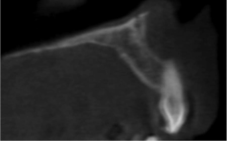
• Assessment of dental trauma (suspected root fracture) (small FOV).
Surgical applications
• Assessment of lower third molars where an intimate relationship with the inferior dental canal is suspected (small FOV)
• Assessment of unerupted teeth (small FOV)
• Cross-sectional imaging prior to implant placement (small or medium FOV)
• Assessment of pathological lesions affecting the jaws (small or medium FOV) including cysts, tumours, giant cell lesions and osseous dysplasias
• Assessment of facial fractures where soft tissue detail is not required (medium or large FOV)
• Planning orthognathic surgery to obtain three-dimensional datasets of the craniofacial skeleton (medium or large FOV)
• Assessment of the bony elements of the TMJ (small or medium FOV)
Clinical examples illustrating many of these indications are included in later chapters.
Equipment and theory
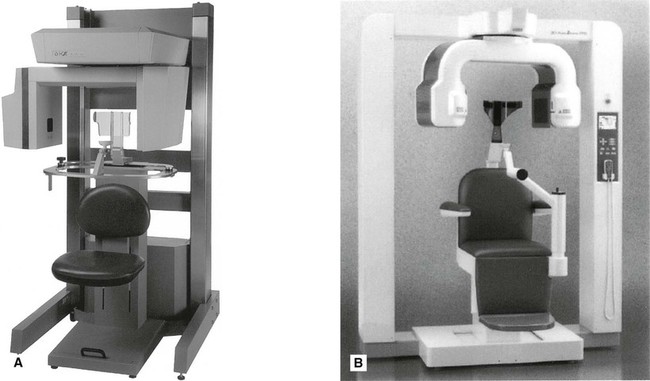
Multiple CBCT machines are currently available with new, upgraded models launched regularly by most manufacturers of X-ray equipment. Almost all modern machines resemble panoramic units, as shown in Fig. 16.1.
All equipment employs a cone-shaped X-ray beam (rather than the flat fan-shaped beam used in conventional CT as described in Chapter 18) and a special detector (e.g. an image intensifier linked to a charge-coupled device (CCD) or, more commonly, an amorphous silicon flat panel). The scanning/image creation process divides into three stages:
Stage 1 – Data acquisition
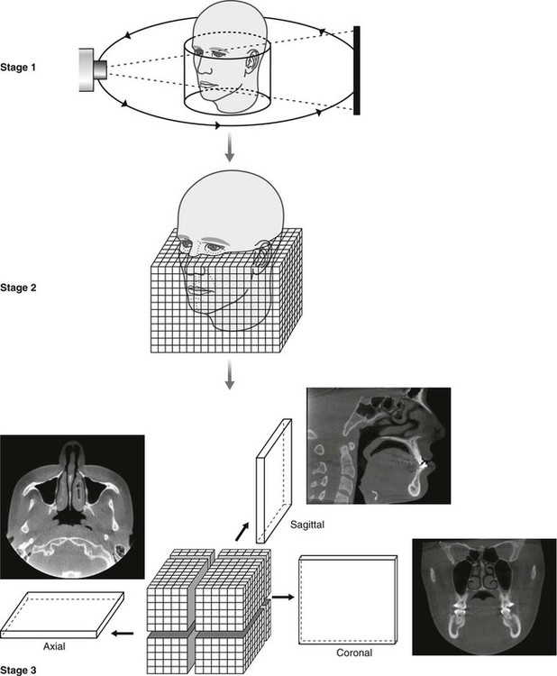
The patient is positioned with the unit (as described later). The equipment orbits around the patient in a 180°, 270° or 360° rotation, taking approximately 5–40 seconds, and in one cycle or scan, images a cylindrical or spherical volume referred to as the field of view (FOV). As all the information/data is obtained in the single scan, the patient must remain stationary throughout the exposure. As described earlier, the FOV can vary in size enabling small, medium or large volumes of a patient to be imaged. Using a large field of view (e.g. 15 cm3) most of the maxillofacial skeleton fits within the cylindrical or spherical shape and is imaged in the one scan as shown in Fig. 16.2.
Stage 2 – Primary reconstruction
Having obtained data from the one scan, the computer then divides the volume into tiny cubes or voxels (ranging in size between 0.076 mm3 and 0.4 mm3) and calculates the X-ray absorption in each voxel. As with pixels in two-dimensional digital imaging, described in Chapter 5, each voxel is allocated a number and then allocated a colour from the grey scale from black through to white. Typically one scan contains over 100 million voxels. The overall image resolution clinically of hard tissues (teeth and bones) is generally very good in CBCT imaging, although measured spatial resolution (3–4 line pairs/mm) is not yet as good as two-dimensional film-based or digital imaging (10–25 lp/mm) (see Chapter 4). Using a smaller voxel size potentially increases the spatial resolution but increases the radiation dose. Even so CBCT cannot be used to examine the soft tissues in detail because of the size of the kV and types of detectors used and the amount of scatter. Essentially all that can be seen is the outline of the soft tissues where it interfaces with air.
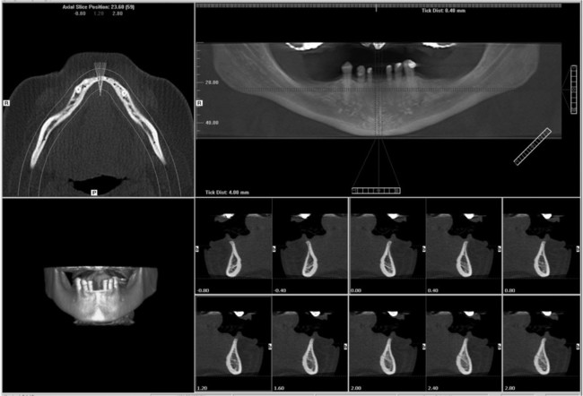
Stage 3 – Secondary or multiplanar reconstruction
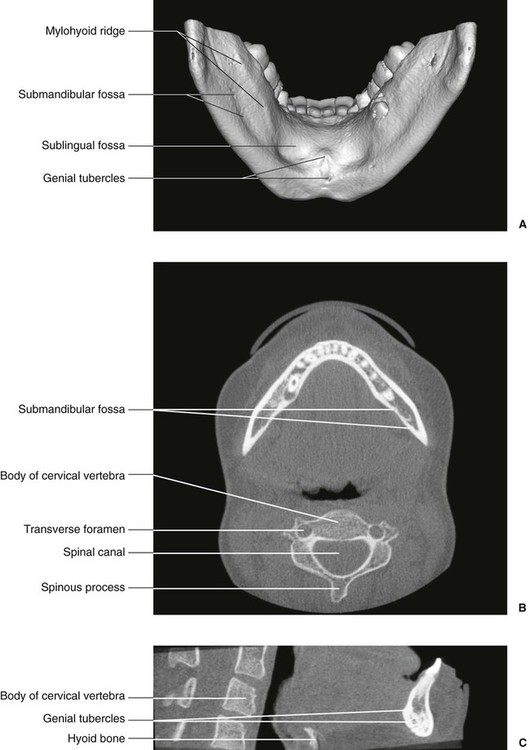
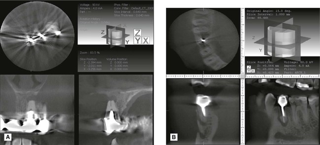
Following the primary reconstruction, the computer software then allows the operator to select voxels in the three anatomical orthogonal planes to create sagittal, coronal or axial images – as shown in Fig. 16.2. A set of sagittal, coronal and axial images appear simultaneously on the computer monitor. The software then enables these image data sets to be scrolled through in real time. For example, by selecting and moving the horizontal cursor up and down on the coronal image, all the axial images can be scrolled through from top to bottom.
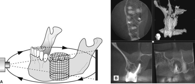
Using a small field of view (e.g. 4 cm3) just two or three teeth and their supporting structures fit within the cylindrical or spherical shape. The same three stages of data acquisition, primary reconstruction and secondary or multiplanar reconstruction are employed to create images in the sagittal, coronal and axial planes, as shown in Fig. 16.3.
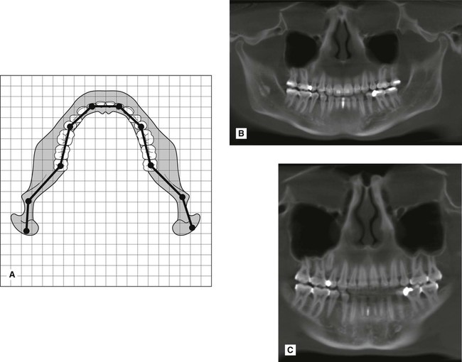
Multiplanar reconstruction also allows voxels in other planes to be selected. For example, it is possible to plot the curvature and shape of the dental arch to enable the computer to construct a panoramic image made up of the voxels that coincide with the plotted arch shape – either mandibular or maxillary (see Fig. 16.4).
In addition, it is also possible to reconstruct cross-sectional (also referred to as transaxial) images of any part of the jaw, and with appropriate software to produce so-called volume rendered or surface rendered images, as shown in Fig. 16.5.
Technique and positioning
As in panoramic radiography, described in Chapter 15, the exact patient positioning techniques vary from one machine to another, but whatever the machine, written protocols for each CBCT examination should be provided which include details of patient positioning, exposure parameters and volume size. There are, however, some general requirements that are common to all machines and these can be summarized as follows.
Equipment preparation
• The smallest volume size needed to answer the clinical question should be used to reduce the radiation dose to the patient. Using a smaller volume reduces scatter and potentially improves image quality.
• Optimal exposure factors should be selected to satisfy the diagnostic requirements of the examination. Higher exposure factors may be chosen if a higher spatial resolution is required.
• Optimal reconstructed voxel size should be selected. If choosing a larger voxel size results in a reduced patient dose (due to lower exposure factors being used) then this should be considered as long as the lower resolution is compatible with the aims of the radiographic examination.
• Some machines offer a ‘quick scan’ where the rotation arc is reduced. This feature reduces the number of projections taken and therefore reduces the dose. If the required diagnostic information can be obtained using this scan protocol then it should be selected.
Patient positioning
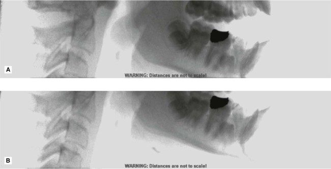
• The patient should be positioned using the manufacturer’s guidelines to ensure that the correct region of interest is captured. A scout view may be useful to ensure the right part of the jaw is imaged, as shown in Fig. 16.6.
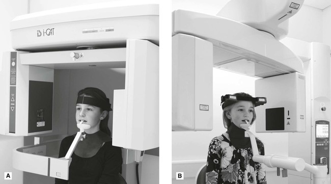
• Once positioned correctly, using the light beam markers, immobilization chin cups and head straps must be used to prevent any patient movement as shown in Fig. 16.7.
• There is no need for the routine use of a protective lead apron.
• There is no need for the routine use of a protective thyroid collar as the thyroid gland does not normally lie in the primary beam, however its use should be considered on a case by case basis particularly in children. If used, it must be positioned so that it does not interfere with the primary beam since this could lead to significant artefacts.
Radiation dose
Typically doses are lower than medical CT but higher than conventional dental radiography. However, some new CBCT units are producing very small field of view, high resolution images with doses equivalent to that of a few periapical radiographs. The effective doses from CBCT imaging, initially shown in Chapter 6, are shown again in Table 16.1.
Table 16.1
Table showing the effective dose from a range of different radiographic examinations including CBCT
| X-ray examination | Effective dose (E) mSv |
| Bitewing/periapical radiograph | 0.0003–0.022 |
| Panoramic radiograph | 0.0027–0.038 |
| Upper standard occlusal | 0.008 |
| Lateral cephalometric radiograph | 0.0022–0.0056 |
| Skull radiograph (PA) | 0.02 |
| Skull radiograph (lateral) | 0.016 |
| Chest (PA) | 0.014 |
| Chest (lateral) | 0.038 |
| CT head | 1.4 |
| CT chest | 6.6 |
| CT abdomen | 5.6 |
| CT mandible and maxilla | 0.25–1.4 |
| Barium swallow | 1.5 |
| Barium enema | 2.2 |
| Dento-alveolar CBCT | 0.01–0.67 |
| Craniofacial CBCT | 0.03–1.1 |
Advantages and disadvantages
Advantages
• Multi-planar reformatting and data manipulation allowing anatomy/pathological conditions to be viewed in different planes
• Lower radiation dose than medical CT
• Geometrically accurate images
• Very good spatial resolution
• Compatible with implant and cephalometric planning software.
Disadvantages
• The patient has to remain absolutely stationary throughout the scan to avoid movement artefacts (see Fig. 16.13)
• Soft tissues not imaged in detail
• Computer constructed panoramic type images are not directly comparable with conventional panoramic radiographs – particular care is needed in their interpretation
• Radiodense objects such as restorations and root filling materials can produce so-called beam hardening artefacts as well as the streak or star artefacts shown in Fig. 16.14.
Assessment of image quality
In the UK the 2010 Health Protection Agency’s guidelines included slightly modified image quality criteria and ratings from those recommended for conventional two-dimensional dental radiographs and shown in several earlier chapters. The recommended subjective image quality ratings and minimum targets for CBCT are shown in Table 16.2.
Table 16.2
| Quality rating | Basis | Target |
| Grade 1 — Diagnostically acceptable | No errors or minimal errors in either patient preparation, exposure, positioning or image reconstruction and of sufficient image quality to answer the clinical question | Not less than 95% |
| Grade 2 — Diagnostically unacceptable | Errors in either patient preparation, exposure, positioning or image reconstruction which render the image diagnostically unacceptable | Not greater than 5% |
Footnote
The regulations and guidelines on the use of cone beam CT vary in different countries. In the UK the Health Protection Agency published Guidance on the safe use of dental cone beam CT in 2010. These address radiation protection issues and compliance with current UK legislation relating to the use of ionizing radiation and quality assurance standards for CBCT testing. A summary of the HPA guidance can be found on-line at www.whaitesessentialsdentalradiography.com
To access the self assessment questions for this chapter please go to www.whaitesessentialsdentalradiography.com
[/level-membership-for-radiology-category][not-level-membership-for-radiology-category]
Cone beam computed tomography (CBCT)
Main indications
The developing dentition
• Localization of an unerupted tooth (small FOV)
• Assessment of external resorption in relation to unerupted teeth (small FOV)
• Localized assessment of an impacted tooth (small FOV)
• Assessment of cleft palate (small or medium FOV)
• Planning complex orthodontic/surgical management of maxillofacial skeletal abnormalities (medium or large FOV).
Restoring the dentition
If conventional imaging proves inadequate, CBCT may be indicated for:
• Assessment of periodontal infra-bony defects and furcation lesions (small FOV)
• Periapical assessment (small FOV)
• Assessment of root canal anatomy in multi-rooted teeth (small FOV)
• Planning surgical endodontic procedures (small FOV)
• Endodontic treatment complicated by resorption lesions, combined perio-endo lesions, perforations and atypical pulp anatomy (small FOV)
• Assessment of dental trauma (suspected root fracture) (small FOV).
Surgical applications
• Assessment of lower third molars where an intimate relationship with the inferior dental canal is suspected (small FOV)
• Assessment of unerupted teeth (small FOV)
• Cross-sectional imaging prior to implant placement (small or medium FOV)
• Assessment of pathological lesions affecting the jaws (small or medium FOV) including cysts, tumours, giant cell lesions and osseous dysplasias
• Assessment of facial fractures where soft tissue detail is not required (medium or large FOV)
• Planning orthognathic surgery to obtain three-dimensional datasets of the craniofacial skeleton (medium or large FOV)
• Assessment of the bony elements of the TMJ (small or medium FOV)
Clinical examples illustrating many of these indications are included in later chapters.
Equipment and theory
Multiple CBCT machines are currently available with new, upgraded models launched regularly by most manufacturers of X-ray equipment. Almost all modern machines resemble panoramic units, as shown in Fig. 16.1.
All equipment employs a cone-shaped X-ray beam (rather than the flat fan-shaped beam used in conventional CT as described in Chapter 18) and a special detector (e.g. an image intensifier linked to a charge-coupled device (CCD) or, more commonly, an amorphous silicon flat panel). The scanning/image creation process divides into three stages:
Stage 1 – Data acquisition
The patient is positioned with the unit (as described later). The equipment orbits around the patient in a 180°, 270° or 360° rotation, taking approximately 5–40 seconds, and in one cycle or scan, images a cylindrical or spherical volume referred to as the field of view (FOV). As all the information/data is obtained in the single scan, the patient must remain stationary throughout the exposure. As described earlier, the FOV can vary in size enabling small, medium or large volumes of a patient to be imaged. Using a large field of view (e.g. 15 cm3) most of the maxillofacial skeleton fits within the cylindrical or spherical shape and is imaged in the one scan as shown in Fig. 16.2.
Stage 2 – Primary reconstruction
Having obtained data from the one scan, the computer then divides the volume into tiny cubes or voxels (ranging in size between 0.076 mm3 and 0.4 mm3) and calculates the X-ray absorption in each voxel. As with pixels in two-dimensional digital imaging, described in Chapter 5, each voxel is allocated a number and then allocated a colour from the grey scale from black through to white. Typically one scan contains over 100 million voxels. The overall image resolution clinically of hard tissues (teeth and bones) is generally very good in CBCT imaging, although measured spatial resolution (3–4 line pairs/mm) is not yet as good as two-dimensional film-based or digital imaging (10–25 lp/mm) (see Chapter 4). Using a smaller voxel size potentially increases the spatial resolution but increases the radiation dose. Even so CBCT cannot be used to examine the soft tissues in detail because of the size of the kV and types of detectors used and the amount of scatter. Essentially all that can be seen is the outline of the soft tissues where it interfaces with air.
[/not-level-membership-for-radiology-category]
