CHAPTER 265 Concepts and Mechanisms of Spinal Biomechanics
Basic Biomechanical Principles
Biomechanically Relevant Anatomy
The vertebral body (VB) is the main axial load–bearing structure of the spine. Its cylindric shape, bounded peripherally by cortical bone and rostrocaudally by end plates, confers it with superior biomechanical properties. The width and depth of VBs increase as one descends in the spine to accommodate increased axial load (Figs. 265-1 and 265-2). The relative weakness of the L5 vertebra can be explained by the asymmetry in height between the ventral and dorsal cortical walls.
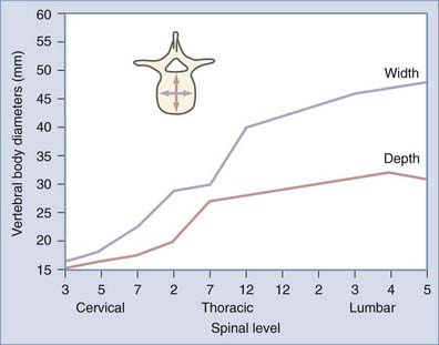
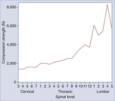
FIGURE 265-2 Vertebral compression strength versus spinal level.
(From Benzel EC. Biomechanically relevant anatomy and material properties of the spine and associated elements. In: Benzel EC, ed. Biomechanics of Spine Stabilization. Rolling Meadows, IL: AANS Publications; and New York: Thieme; 2001:4. Reprinted by permission.)
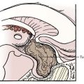
The intervertebral disk serves as a shock absorber and is the primary stabilizing structure of the motion segment. It is composed of the nucleus pulposus (a hydrated core of proteoglycans suspended in a loose collagen network) located in the posterocentral area of the disk and the annulus fibrosus (a fibrocartilaginous ring designed to provide structural support). The loads that these structures must tolerate cyclically for decades is impressive. Compressive loads on the lumbar intervertebral disks are 1.0 to 2.5 times body weight during normal walking. During the lifting of 14- to 27-kg objects, axial compressive loads in the lumbar spine increase up to nearly 10 times body weight, with anteroposterior shear loads approaching double body weight.1,2 Concentric axial loads cause equally distributed forces within the disk, whereas eccentrically placed loads result in bulging of the annulus on the side of the applied force along with associated displacement of the nucleus to the opposite side (Fig. 265-3). Shearing and rotational forces are resisted by the annular fibers, which lie at a 30-degree angle with respect to each other. As the disk deteriorates, its isotropic load transfer properties are lost and load transfer becomes concentrated at the periphery (annular insertion) of the vertebral end plates.3,4
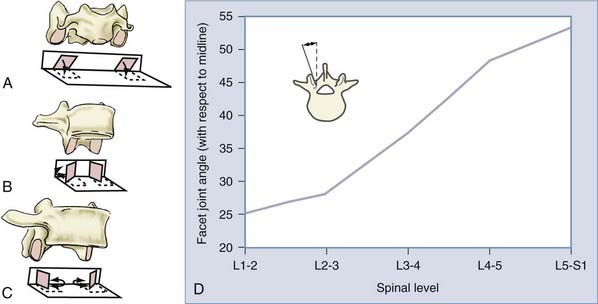
In conjunction with the intervertebral disk, the facet joints provide additional load-bearing and stabilizing functions between segmental levels. Their orientation (Fig. 265-4) serves to facilitate or limit degrees of motion (Fig. 265-5) and therefore plays an important role in spinal stability. The cervical facets are coronally oriented and resist translation while facilitating flexion, extension, and rotation. Conversely, the lumbar facets are sagittally oriented (with the exception of L5-S1) and resist rotation while allowing significant flexion and extension. The thoracic facets are intermediately oriented and thus provide an “intermediate” restriction of translation and rotation. Both extension and ventral translation tend to load facets, whereas flexion and dorsal translation unload them. Degeneration of the intervertebral disk, loss of disk height, and alterations in sagittal alignment result in greater load transfer to the facet joints.
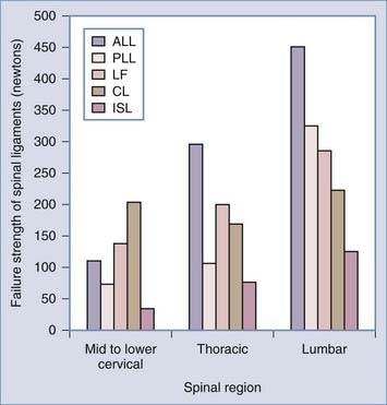
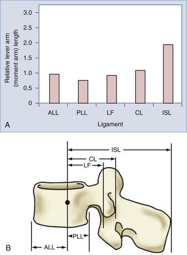
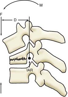
The spinal ligaments provide passive stabilization of the vertebral column. Their bone-to-bone interface and elastic properties provide both tension band and translational support. The tension band contribution to spinal stability is related to both the ligament’s tensile strength (Fig. 265-6) and the moment arm through which it acts. As discussed later, the moment arm is the perpendicular distance from the instantaneous axis of rotation (IAR) to the applied force vector. The amount of resistance (counterbending moment) that a ligament provides is proportional to its distance from the IAR (Fig. 265-7).
As opposed to the skeletal muscles, which generate long bone motion and span one or two articulations, the paraspinous musculature (and associated abdominal musculature) spans multiple segments (Fig. 265-8). The primary function of the paraspinous musculature is to stabilize the spinal column rather than produce motion. An exception is the action of the erector spinae muscles when arising from a forward flexed position. In general, any imbalance in muscular forces causes movement about an axis. Conversely, a balancing of muscle and other intrinsic forces about an axis results in no net movement. The ventral abdominal musculature is critical in counterbalancing the erector spinae muscles to provide stability.
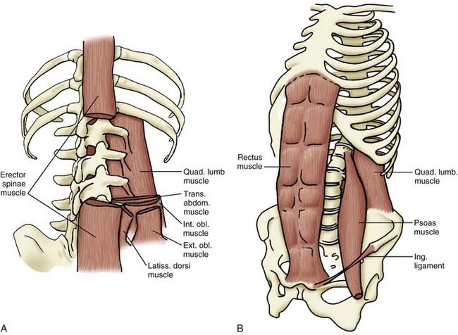
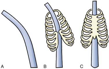
The rib cage, acting as a barrel attached to the spine, adds significant stability to the upper and middle thoracic segments. Both the costovertebral and costosternal joints are essential to this contribution (Fig. 265-9).
Basic Biomechanical Principles
Biomechanical analysis assesses the effects of energy and forces on biologic systems by using physics and physical principles that have well-accepted definitions. A reference for many of these definitions can be found in Table 265-1.5,6
| Kinematics | Study of the motion of objects without considering the factors that cause or affect the motion. The latter is the subject of dynamics. |
| Momentum | Product of mass and velocity |
| Moment | Circular force creating a rotational vector around an axis |
| Torque/bending moment | Product of the force applied to the lever arm multiplied by the perpendicular distance from the axis |
| Coupling | When more than one non-collinear force acts about the same axis and the resultant force moment is the sum of the individual forces |
| Stress | Force/load applied to an object divided by its cross-sectional area |
| Strain | Change in length of an object secondary to a deforming force |
| Stress/strain | Aids in defining an object’s intrinsic material properties |
| Stiffness | Relationship of stress or force and strain or deformation |
| Deformation | Change in shape or size secondary to stress and strain on an object from applied forces and moments. It is a structural property of a material that depends on the shape, size, and intrinsic material properties. |
| Elastic deformation | Occurs when strain on a material is totally recovered once the stress is removed |
| Plastic deformation | Occurs at the point where stress is no longer proportional to strain |
| Yield point | Point at which elastic deformation becomes plastic deformation |
| Ultimate tensile strength/breaking point | Point at which an object fails |
| Strength | Maximum stress that a material can sustain—coincides with the area under the stress-strain curve to the point of its ultimate tensile strength |
| Intrinsic material properties | Independent of an object’s shape and size—thus, its study requires that the effect of the object’s shape and size (geometry) be eliminated. |
| Ductile | Materials with intrinsic properties that allow permanent deformation before failure |
| Brittle | Materials with intrinsic properties that cause failure before permanent deformation |
| Hooke’s law | The degree of elastic deformation of a solid object is proportional to the deforming force, and the elastic modulus is a measure of the deformability of a solid object. |
| Isotropic objects | Intrinsic material properties independent of the direction of loading and with a randomly dispersed internal structure (metal, glass, plastic) |
| Anisotropic objects | Intrinsic material properties dependent on the direction of loading and with an orderly internal structural arrangement (bone, intervertebral disks, ligaments/tendons) |
Measurements of Force
The IAR also changes with the spinal level and migrates during intervertebral motion. The flexion-extension IAR of a cervical or lumbar motion segment is slightly dorsal and caudal to the center of the caudal vertebral end plate. An exception to this position is found at L5-S1. At this level the IAR lies within the disk space instead of below the caudal end plate. The IAR also moves proximally when going from C2 to C7. Changes in the IAR are important because they can result in excessive facet joint or posterior ligamentous loading.4
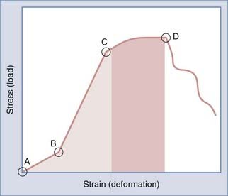
Deformation and Elasticity
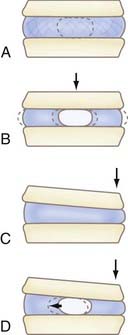
The shape of all solids can be altered by external forces. For small displacements, the size of the deformation is proportional to the deforming force. This is known as Hooke’s law. Although valuable for analyzing the effects of force on various spinal instrumentation/constructs, it becomes unreliable with larger displacements because the neutral zone (component of the physiologic range of motion associated with significant flexibility and minimal stiffness at small loads) is exceeded and the elastic limit of the material is reached. The elastic limit is the point at which the force’s linear relationship departs from being linear between the size of deformation and the deforming force and results in permanent distortion. At its extreme, the solid may break; this is known as the point of failure (Fig. 265-10).
Stability versus Instability
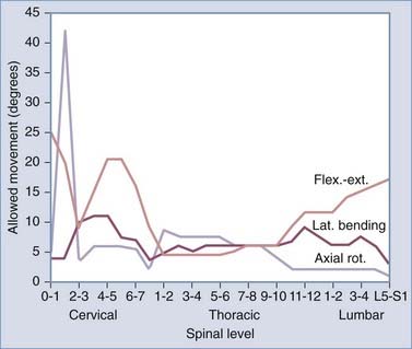
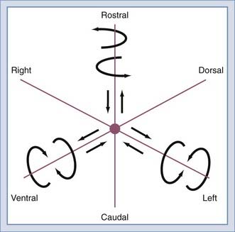
The inherent structure of the spine provides a physiologic and functional degree of freedom of motion. Normal range of motion includes translation and rotation about the three anatomic axes (Fig. 265-11) to provide six potential movements referred to as degrees of freedom. Segmental motions at the various spinal levels (see Figs. 265-4 and 265-5) are generally determined by facet orientation, bony anatomy, associated ligaments, and supporting structures.
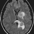
Limited instability is defined as the loss of either ventral or dorsal spinal integrity with preservation of the other. This is sufficient to support most normal activities. Isolated laminar fractures or ligamentous disruption (as illustrated on fat suppression T2-weighted MRI) with intact ventral elements is an example. Conversely, isolated wedge or burst vertebral fractures, with preserved integrity of the dorsal elements, are considered to constitute limited instability. Occasionally, underestimation of dorsal ligamentous injury may lead to overt instability being mistaken for limited instability. This is less likely if MRI is used liberally. Dynamic flexion-extension radiographs may also be useful in the context of limited instability. Dynamic radiographs may be misleading when guarding is present and may even be dangerous when underlying overt instability is present. Clinical judgment must guide the use of such imaging. Limited instability is usually managed nonoperatively with bracing. Surgery may be indicated if there is a significant risk for chronic instability (Table 265-2).
| TYPE | EXAMPLES |
|---|---|
| Overt | Inability of the spine to support the torso during normal activity |
| Limited | Loss of either ventral or dorsal spine integrity, with the preservation of the other |
| Glacial | Instability that is not overt and does not demonstrate a significant chance of rapid development of progression of the deformity but, like a glacier, progresses gradually with time. Substantial external forces do not cause movement or progression of the deformity. |
Implant Properties
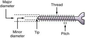
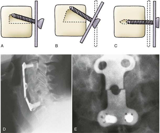
Many constructs depend on screws to maintain attachment to the spine. The important anatomic aspects of a screw include the head, core, thread, and tip. Inner diameter can remain constant along the length of the screw or taper. Section modulus remains unchanged along the length of the screw in the former and rises exponentially in the latter. Pullout resistance is proportional not only to the volume of bone between screw threads but also to the triangular area defined by the screw: the perpendicular and dorsal VB surface. Alterations in thread pitch and distance between threads affect the interthread bone volume. Although screw length does not contribute significantly to pullout resistance, rigidly triangulated screws significantly increase resistance. Thus, increasing the screw angle (toe-in) increases the triangular area and thus pullout resistance (Fig. 265-12).
The Aging Spine
Cervical Spondylosis and the Aging Spine
The degeneration associated with aging has a significant impact on the spinal column’s fundamental biomechanics. As would be expected, younger spinal columns are more flexible and exhibit a significantly greater range of motion than do their older counterparts7–10 as a result of an accumulation of changes, including facet joint osteoarthritis, dehydration of the intervertebral disk, and loss of normal spinal alignment.10 It seems that the cervical region is most susceptible to these changes, in part because of its high degree of mobility, as well as the more complex geometry of the uncovertebral joints.10
Spondylosis
Many of the changes associated with age start at the microscopic level. The functional proteoglycans in cartilage decrease significantly with age, thereby resulting in a gradual reduction in the tissue’s water-binding properties and an associated decrease in its shock-absorbing ability, as well as increasing friability.11 Stiffness of the cartilage also increases, partially as a result of increased cross-linking between fibrous proteins, especially the collagens.12 Both these changes result in increased susceptibility of the cartilage and tendinous attachments to injury. The intervertebral disks also lose much of their functional ability with age. Although this is probably the result of millions of load cycles throughout an individual motion segment’s functional life span, it is accelerated by an age-related decline in transport of metabolites within the avascular matrix.13 As one would surmise, this also increases the disk’s vulnerability to injury.
Osteoporosis
The aging process is commonly associated with a gradual decrease in bone mineral density that can lead to osteoporosis and fracture. Because these changes are generally initiated in cancellous bone, the VBs of the spine are often involved.14 The compressive strength of cancellous bone is related to the square of the apparent density, and the elastic modulus is also related to the apparent density.15 Thus, the strength of the VB and its resistance to axial loading are immediately compromised. However, the process is more complex. As an adaptive response to decreased bone mineral density, the trabecula of the bone remodel. Specifically, the ratio of vertical to horizontal trabecular orientation increases, especially in the anterior third of the VB. As this ratio increases, the ability of the VB to resist axial loads becomes greater, and so does the directional dependency of load resistance. The decrease in horizontal trabecula results in a decrease in elastic modulus and strength in the transverse direction and an increased vulnerability to forces other than pure axial. This could partially explain the higher incidence of VB fractures associated with osteoporosis in the anterior part of the VB (wedge fracture).14 Thus, although an osteoporotic VB adapts to resist axial loads, it sacrifices its ability to withstand loading in directions different from the direction of the principal trabecular orientation or the shear load.
Spinal Alignment
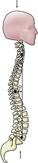
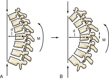
Age-related postural changes affect the relative orientation of adjacent vertebrae and profoundly alter stress distributions within the apophyseal joints and intervertebral disks. A perfectly straight spine would theoretically be an ideal axial-loading spinal configuration, but it would tolerate eccentric loads poorly and provide limited flexibility. The spine has therefore evolved to adopt a curvilinear sagittal conformation—with a primary kyphotic thoracic curve compensated by secondary cervical and lumbar lordotic curves of equal summative magnitude. This results in a balanced configuration that is necessary for a bipedal upright posture (Fig. 265-13). Any increase in thoracic kyphosis (or loss of lumbar lordosis) leads to an increased moment arm (i.e., perpendicular distance from the IAR to the gravitational force vector), which generates a greater bending moment at each vertebral segment (Fig. 265-14). The moment arm (M) is equal to the force (F) multiplied by its perpendicular distance (D) from the IAR (M = F × D). The greater the deformity, the greater the length of the moment arm; hence, “deformity begets deformity.” The same mechanism applies to deformities in the coronal plane (scoliosis) (Fig. 265-15).
Biomechanics of Intervention
Construct Design Principles
Construct Failure
Degradation of the screw-bone interface results in toggling of the screw (moving in a windshield wiper motion). Sufficient force can also result in the screw cutting or pulling out of the bone. Long rigid (fixed moment arm) constructs tend to load the more caudal screws far more than the rostral screws and are associated with a high failure rate (Fig. 265-16).
Bone-Bone Interface Failure
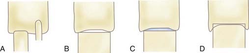
Factors affecting the incidence and extent of nonunion/subsidence include the closeness of fit of the bone graft in the VB mortise, the surface area of contact between the bone graft and VB, and the character or quality of the contact surfaces. The extent of end plate preservation and proximity of the contact point to the edge of the VB affect the quality of the contact surfaces. Greater construct strength is achieved when the cortical portion of a graft is positioned in line with the cortical surface of the VB. Some implants take advantage of the boundary effect by providing support at the edge of the VB, thus maximizing resistance to axial loading. The greatest biomechanical advantage with respect to interbody axial load-bearing ability is achieved when a strut graft is nearly the same size as the VB in terms of contact surface area. Creation of a lateral buttressing effect can help minimize bone-bone interface failure, and lateral fit of the bone graft against the wall of the corpectomy trough further optimizes the interbody bone-bone interface relationships. Increasing bone-bone contact surface area will decrease the chance of graft pistoning (Fig. 265-17).
Biomechanics of Nonfusion Implants
Biomechanics of Nuclear Implants
Nucleus pulposus replacement implants are designed to restore disk turgor and tension in the annulus fibrosus, as well as reestablish the disk’s ability to transfer loads uniformly across the disk space.3 Remodeling of the VB end plates has been observed after nuclear replacement. Such remodeling is probably the result of changes in load concentration on the end plates after placement of the device and is being addressed by increasing the area of the device in contact with the end plate, as well as by minimizing implant stiffness.
Biomechanics of Total Disk Replacement
To avoid wear-related failure and progressive facet joint arthrosis and minimize the effect on adjacent motion segments, TDR biomechanics needs to be as close to the original disk as possible. Biomechanical constraint of the TDR, defined as the limitation of pure anteroposterior or lateral translational intervertebral motion, will affect the stress on the remaining facet joints. The ball-and-socket articulation TDRs have much higher constraint and secondarily less shear translation. Because facet cartilage tends to be loaded by anterior shear loads, the more constrained implants are able to reduce loading of the facets at the expense of greater loads on the implant and the implant-bone interface.3 Similarly, less constrained TDRs may allow increased facet loading. Contrarily, a constrained TDR dictates the arc or rotation. This can result in increased loading of the facets, especially at the extremes of motion.3
In constrained TDRs, the location of the IAR and the radius of curvature of the articulation are important predictors of its biomechanical characteristics. A relatively posterior IAR better reflects the physiologic IAR and results in greater range of motion.16 The radius of curvature is the distance from the IAR to the implant’s surface, and this determines the relative proportion of rotation and apparent translation observed in a ball-and-socket joint. With a small (round) radius of curvature, rotation dominates. With a large (flat) radius of curvature, translation dominates. Although the interplay of flexion-extension and translational motion affects facet loading, its preservation is important in reducing stress on adjacent levels, one of the primary goals of TDRs.
Biomechanics of Posterior Stabilization Devices
The goals of posterior stabilization devices (restriction of specific motion, alteration of load transfer, unloading of the disk and facet) are quite different from those of TDRs or nuclear replacements. The most commonly used of these devises consists of pedicle screws connected by prosthetic ligaments with or without compression-resistant sleeves intended to maintain a normal or lordotic apposition of the facet joints. Fixation in lordosis unloads the anterior disk and increases force on the posterior annulus and facets. It can also move the IAR posteriorly so that the posterior annulus acts as a fulcrum between the tensile forces applied by the device and the compressive forces applied across the disk space. Theoretically, these biomechanical shifts can lead to increased wear of the dorsal annulus, as well as the development of iatrogenic lateral recess stenosis.3 Placement of compression-resistant sleeves around the prosthetic ligaments can prevent excessive lordosis and aid in load transfer. Although the addition of these sleeves can reduce the incidence of posterior annulus overload, they can result in a significant increase in the rigidity of the construct, as well as the compressive moment on the pedicle screw. This could lead to loosening or breakage. These devises are also not intended to produce bony fusion and are thus at increased risk for fatigue failure from cyclic loading.
Conclusion
An understanding of fundamental biomechanical principles is essential in spine surgery. Although this chapter is brief, hopefully it provides a sufficient overview of the subject to wet the appetite of aspiring spinal neurosurgeons and motivate further reading on the subject.17 As the understanding of these rules and caveats deepen, surgeries will become more successful and patients (as well as surgeons) will be happier with their outcomes.
Benzel E. Biomechanics of Spine Stabilization: Principles and Clinical Practice. New York: McGraw-Hill; 2004.
Benzel EC. The essentials of spine biomechanics for the general neurosurgeon. Clin Neurosurg. 2003;50:86.
Huang RC, Wright TM, Panjabi MM, et al. Biomechanics of nonfusion implants. Orthop Clin North Am. 2005;36:271.
1 Granata KP, Marras WS, Davis KG. Variation in spinal load and trunk dynamics during repeated lifting exertions. Clin Biomech (Bristol, Avon). 1999;14:367.
2 Cappozzo A. Compressive loads in the lumbar vertebral column during normal level walking. J Orthop Res. 1984;1:292.
3 Huang RC, Wright TM, Panjabi MM, et al. Biomechanics of nonfusion implants. Orthop Clin North Am. 2005;36:271.
4 Yoshioka T, Tsuji H, Hirano N, et al. Motion characteristic of the normal lumbar spine in young adults: instantaneous axis of rotation and vertebral center motion analyses. J Spinal Disord. 1990;3:103.
5 Benzel EC, Kayanja M, Fleischman A, et al. Spine biomechanics: fundamentals and future. Clin Neurosurg. 2006;53:98.
6 Benzel EC. The essentials of spine biomechanics for the general neurosurgeon. Clin Neurosurg. 2003;50:86.
7 Kumaresan S, Yoganandan N, Pintar FA, et al. Contribution of disc degeneration to osteophyte formation in the cervical spine: a biomechanical investigation. J Orthop Res. 2001;19:977.
8 Ng HW, Teo EC, Zhang Q. Influence of cervical disc degeneration after posterior surgical techniques in combined flexion-extension—a nonlinear analytical study. J Biomech Eng. 2005;127:186.
9 Pintar FA, Yoganandan N, Voo L. Effect of age and loading rate on human cervical spine injury threshold. Spine. 1998;23:1957.
10 Board D, Stemper BD, Yoganandan N, et al. Biomechanics of the aging spine. Biomed Sci Instrum. 2006;42:1.
11 Bayliss MT, Hutton S, Hayward J, et al. Distribution of aggrecanase (ADAMts 4/5) cleavage products in normal and osteoarthritic human articular cartilage: the influence of age, topography and zone of tissue. Osteoarthritis Cartilage. 2001;9:553.
12 Duance VC, Crean JK, Sims TJ, et al. Changes in collagen cross-linking in degenerative disc disease and scoliosis. Spine. 1998;23:2545.
13 Horner HA, Urban JP. Volvo Award Winner in Basic Science Studies: Effect of nutrient supply on the viability of cells from the nucleus pulposus of the intervertebral disc. Spine. 2001;26:2543.
14 Chao EY, Inoue N, Koo TK, et al. Biomechanical considerations of fracture treatment and bone quality maintenance in elderly patients and patients with osteoporosis. Clin Orthop Relat Res. 2004;425:12.
15 Carter DR, Hayes WC. The compressive behavior of bone as a two-phase porous structure. J Bone Joint Surg Am. 1977;59:954.
16 Dooris AP, Goel VK, Grosland NM, et al. Load-sharing between anterior and posterior elements in a lumbar motion segment implanted with an artificial disc. Spine. 2001;26:E122.
17 Benzel E. Biomechanics of Spine Stabilization: Principles and Clinical Practice. New York: Mcgraw-Hill; 2004.