CHAPTER 5 Computed Tomography, Ultrasound, and Imaging-Guided Injections of the Hip
Computed tomography
Two- and Three-Dimensional Reformatted Computed Tomography Images
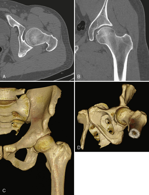
Before the invention of MDCT scanners, the ability to reformat the original axial data set into other imaging planes was markedly limited. The resulting images were often distorted with a venetian-blind effect with steplike contours, and thus they were of limited diagnostic quality. With the advent of MDCT scanners, however, this has dramatically improved. The reason behind this is the concept of isotropic imaging. If a volume of tissue (i.e., a voxel) is imaged at a very small quantity such that the length, width, and height of the volume are equal, then a reformatted image retains high resolution as compared with the axial images (Figure 5-1, A and B). It is possible to obtain these images with the use of MDCT scanners with 16 or more detector rows that allow for a slice thickness of less than 1 mm. A standard protocol for the imaging of any extremity with CT is to reconstruct the original data at a slice thickness of less than 1 mm with 50% overlap of each slice and to then produce two-dimensional reformatted images 1- to 2-mm thick in the axial, sagittal, and coronal planes. MDCT scanners now have several options or tools that allow for three-dimensional reformatted imaging and surface rendering. At an independent workstation, these data can be manipulated to remove overlying soft tissues, osseous structures, or hardware and to produce a rotating volumetric data set (Figure 5-1, C and D).
Femoroacetabular Impingement and Computed Tomography Arthrography
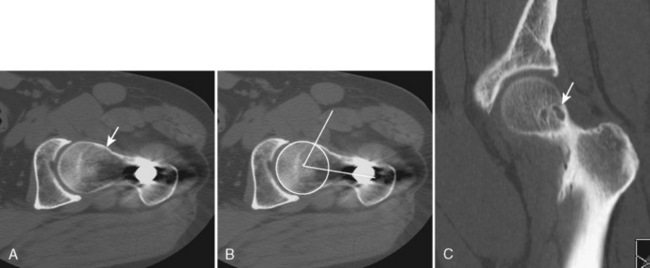
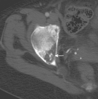
Many of the imaging features of FAI include bony abnormalities. Although magnetic resonance imaging (MRI) has also been used to demonstrate these findings, CT is well suited for characterizing bone abnormalities (Figure 5-2, A). With the cam type of FAI, the abnormal contour at the femoral head–neck junction is measured as the alpha angle, which indicates where the bone contour of the femoral head extends beyond the confines of the femoral head. An angle of more than 55 degrees measured on a sagittal–oblique image parallel to the femoral neck is considered abnormal and correlates with the cam type of FAI (Figure 5-2, B). Other bony changes associated with the cam type of FAI are well demonstrated with CT, including fibrocystic changes at the anterosuperior femoral neck (Figure 5-2, C). Such fibrocystic changes are more common among patients with FAI, and they may be directly caused by impingement. CT has an advantage over radiography for showing such cortical changes. Other radiographic signs of the cam type of FAI, such as the abnormal contour of the femoral head–neck junction (pistol grip deformity), are also well delineated on CT, because patient positioning may not optimally profile the bone contour deformity.
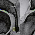
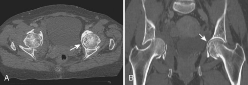
With regard to CT of the pincer type of FAI, bony abnormalities such as acetabular protrusion (Figure 5-3) and acetabular retroversion may be demonstrated. When assessing for acetabular retroversion on radiography, the crossover sign (i.e., the anterior acetabular wall projects lateral to the posterior acetabular wall) may be affected by patient positioning. CT avoids this pitfall by directly measuring the acetabular version, which is described as 23 degrees in females (range, 10 to 37 degrees) and 17 degrees in males (range, 4 to 30 degrees). A retroverted acetabulum is associated with the pincer type of FAI and with hip osteoarthrosis. CT is also effective for measuring anterior and posterior acetabular sector angles in the setting of hip dysplasia.
Hip Trauma
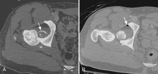
CT is often used to evaluate the hip and acetabulum after hip dislocation and other pelvic trauma (Figures 5-3 and 5-4). When an acetabular fracture is identified by radiography, CT can further characterize the fracture pattern with the use of multiplanar reformatted images and three-dimensional surface rendering (see Figure 5-3). Associated abnormalities such as intra-articular bodies and pelvic hematoma are also well demonstrated with CT. After hip dislocation, CT demonstrates the position of the femoral head and the coexisting femoral head fracture (see Figure 5-4, A). A sign of prior hip dislocation on CT is the presence of a bubble of gas, which is most commonly seen at the anterior aspect of the hip joint (see Figure 5-4, B).
It is important to understand the advantages and disadvantages of CT for the evaluation of fracture. CT is most accurate for demonstrating fractures of cortical bone (Figure 5-5, A). In an osteopenic patient in whom the cortex is thin, accuracy will decrease, especially when the fracture is not displaced. This becomes even more problematic for the diagnosis of an intramedullary fracture. In an osteopenic patient in whom the trabeculae are thin or resorbed, a fracture may not be apparent on CT. MRI has been shown to be more accurate than CT for the evaluation of proximal femur fractures in patients more than 50 years old where CT led to a misdiagnosis in 66% of patients. In addition, CT may not show the entire intramedullary extent of a presumed isolated greater trochanteric fracture. As a general rule, CT is most effective for diagnosing fractures of cortical bone in younger patients, and it is relatively limited with regard to intramedullary fractures among the elderly (e.g., insufficiency-type stress fractures). By contrast, a chronic-fatigue–type stress fracture is well demonstrated with CT given the associated sclerosis (Figure 5-5, B).

Hip Arthroplasty
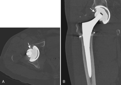
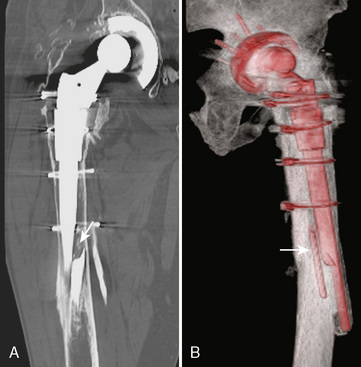
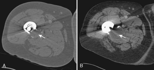
Although radiography is the imaging method of choice for the routine evaluation of the hip after arthroplasty, CT does have a role in specific scenarios, such as the evaluation of infection, osteolysis, and component position. The technical advance that permits for the CT evaluation of metal with reduced artifact is MDCT, which allows increased x-ray tube current to image through metal. The individual components of an arthroplasty as well as the adjacent soft tissues and bone can be visualized with CT (Figure 5-6). This is helpful for displaying fracture (Figure 5-7) and for the diagnosis of soft-tissue infection adjacent to a prosthesis (Figure 5-8). In the presence of component wear and particle disease, CT can directly show the polyethylene component wear as well as the adjacent osteolysis (Figure 5-9). Although radiography adequately screens for osteolysis, CT more accurately measures the volume of osteolysis. CT can also be used to measure component version after hip arthroplasty.
Miscellaneous Hip Abnormalities
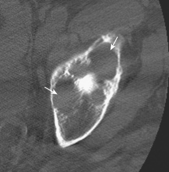
Other hip disorders that involve the bone or that produce calcification or ossification can be evaluated with CT. Primary synovial osteochondromatosis is a benign neoplastic condition in which hyaline cartilage nodules form in the subsynovial tissue of a single large joint. If these nodules ossify, they are readily demonstrated on CT as multiple uniform ossific bodies in the joint (Figure 5-10). Secondary osteoarthrosis and associated erosions may also be present. The hip is the second most common joint affected by this condition, after the knee.
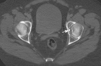
Figure 5–10 Synovial osteochondromatosis. Axial CT image shows several ossified cartilaginous bodies (arrow).
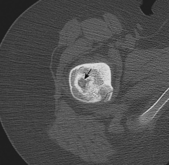
Osteoid osteoma is a benign bone lesion of uncertain origin that involves a vascularized nidus being present within the bone, typically the cortex. When this occurs in an extra-articular location, the nidus is associated with significant sclerosis and periostitis (Figure 5-11). When it is intra-articular, there is associated effusion and synovitis. CT shows the nidus as a round area of low attenuation with surrounding sclerosis that may calcify. CT can be used to effectively guide the percutaneous thermoablation of osteoid osteomas.
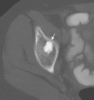
CT may also be used to characterize other bone abnormalities. When a sclerotic focus is present within the bone, CT can show the uniform sclerotic density and spiculated margins that are typical of a bone island or enostosis (Figure 5-12). The calcified matrix of a chondroid tumor such as chondroblastoma or chondrosarcoma (Figure 5-13) or the ossified matrix of an osteosarcoma can be demonstrated with CT, which assists with the characterization of a primary bone tumor. CT is the typical imaging method used for the percutaneous imaging-guided biopsy of a bone tumor that involves the pelvis or the proximal femur.
Ultrasound
Joint Abnormalities
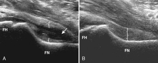
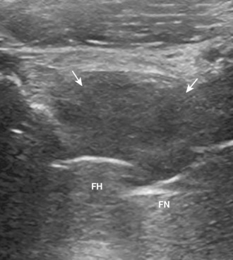
Ultrasound can be used to identify a hip effusion, which characteristically distends the anterior recess over the femoral neck (Figure 5-14). Joint effusion is diagnosed when there is 2 mm or more of fluid between the anterior capsule and posterior capsular reflection, when the hip capsule over the femoral neck measures 7 mm or more, or when there is a difference in distention of more than 1 mm as compared with the normal contralateral side. The collapsed joint recess with its capsular reflection may measure up to 7 mm and appear to be hyperechoic, but this can appear hypoechoic if it is not imaged perpendicular to the ultrasound beam or if the patient is large. A simple effusion is anechoic, whereas complex fluid will appear to be hypoechoic with possible internal echoes. Synovitis is characterized by hypoechoic to variable echogenicity distention of the joint recess with possible increased flow on color or power Doppler imaging (Figure 5-15). Ultrasound cannot differentiate septic from aseptic effusion; therefore, aspiration should be considered when there is concern about infection. The accuracy of ultrasound for the diagnosis of hip effusion depends on the quantity of fluid and the size of the patient; ultrasound is very accurate in children and thin adults, whereas the diagnosis may be difficult in adults with a large body habitus. When screening for joint effusion, a negative ultrasound should be followed with a fluoroscopy-guided aspiration in a large patient when there is high clinical concern regarding infection. Although the anterior labrum can be visualized with ultrasound as a hyperechoic triangle-shaped structure, the diagnosis of labral tear is limited as a result of the thickness of the soft tissues over the labrum and the inability to visualize the entire labrum.
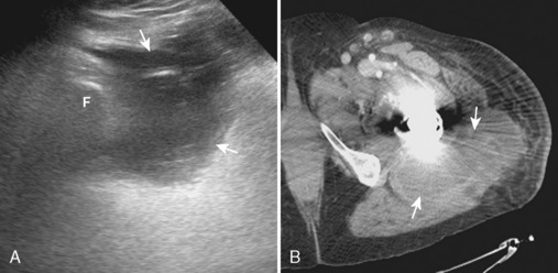
Ultrasound for the diagnosis of hip joint effusion after hip arthroplasty is more limited as compared with a native adult hip, likely as a result of postsurgical changes in the soft tissue and possible patient body habitus size. Although ultrasound may show a large effusion, a small effusion may be overlooked. A negative ultrasound should be followed with a fluoroscopic-guided hip joint aspiration if there is a high concern about infection. Ultrasound does have a significant role in the evaluation of infection after arthroplasty for evaluating the overlying soft tissues for abscess before fluoroscopic aspiration, thereby avoiding the passage of a needle through an occult abscess with resulting contamination of the joint. Ultrasound may also show bursae or other fluid collections that will not be visible during fluoroscopy (Figure 5-16). The region deep to a skin incision should be evaluated for postoperative fluid collection or abscess. The identification of soft-tissue fluid that extends from the hip joint suggests infection.
Bursal Abnormalities
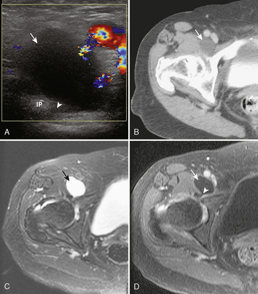
The iliopsoas bursa is located anterior to the hip and communicates with the hip joint in up to 15% of individuals; this number is increased in the presence of hip pathology. Distention of the iliopsoas bursa produces a characteristic shape that is concave lateral as it wraps around the iliopsoas tendon (Figure 5-17). Communication between the iliopsoas bursa and the hip joint can be demonstrated with imaging. Similar to the hip joint, the distention of the bursa may appear as anechoic simple fluid, mixed echogenicity complex fluid, and hypoechoic to variable echogenicity synovitis with possible flow on color or power Doppler imaging. A chronically distended iliopsoas bursa may enlarge significantly and extend cephalad into the abdomen. It is important in this situation to not mistake a large iliopsoas bursa for a psoas abscess.
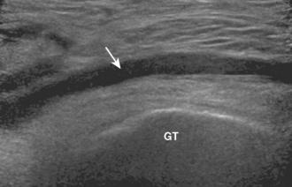
There are three bursa that are located near the greater trochanter of the femur: the subgluteus minimus bursa (anterolaterally between the gluteus minimus and greater trochanter), the subgluteus medius bursa (laterally between the gluteus medius and the greater trochanter), and the trochanteric bursa (posterolaterally between the gluteus maximus and the greater trochanter with some extension over the gluteus medius). It is important to evaluate the circumference of the greater trochanter and to evaluate for the distention of these bursae between their respective tendons and the greater trochanter. As with the iliopsoas bursa, distention can range from anechoic to mixed echogenicity, depending on whether there is simple fluid, complex fluid, or synovitis distention (Figure 5-18).
Muscle and Tendon Abnormalities
Muscle or tendon tear is characterized as the disruption of tendon fibers with anechoic or hypoechoic fluid or hemorrhage. The presence of tendon retraction suggests a full-thickness tear. By contrast, the hypoechoic thickening of a tendon without tendon fiber disruption is characteristic of tendinosis. If a tendon has a tendon sheath, the distention of the tendon sheath indicates tenosynovitis; similar to joint recess distention, this can range from anechoic to mixed echogenicity distention. Ultrasound is useful for the diagnosis of iliopsoas impingement from an adjacent hip arthroplasty, because prosthesis artifact occurs deep and away from the overlying soft tissues (Figure 5-19).
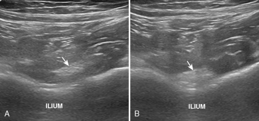
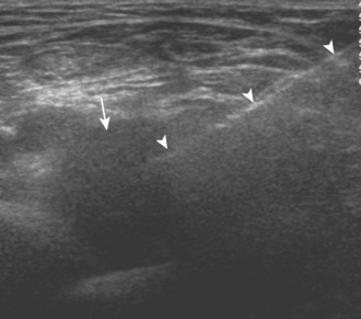
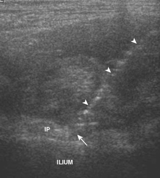
Ultrasound is well suited for evaluating for snapping tendon abnormalities around the hip given its dynamic capabilities, which allow for examination during hip or leg motion. Snapping hip syndrome represents a number of pathologies that cause painful snapping of the hip during motion. These conditions can be divided into internal (hip joint) and external (iliopsoas, iliotibial tract, or gluteus maximus) causes. With regard to the external causes, these relate to the abnormal snapping of a tendon or muscle during motion. Iliopsoas tendon snapping occurs when the leg is straightened from a frog-leg position, which causes the abrupt movement of the iliopsoas tendon in the region of the iliopectineal eminence of the ilium (Figure 5-20). Iliotibial tract or gluteus maximus snapping may occur over the greater trochanter with hip flexion and extension, and there will be abrupt snapping of the representative structure. In each situation, a palpable snap may be felt through the transducer, which corresponds with the abrupt motion of the structure during ultrasound and when the patient is experiencing symptoms. Ultrasound-guided injection may be used for treatment.
Imaging-guided injections
Joint Injection
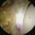
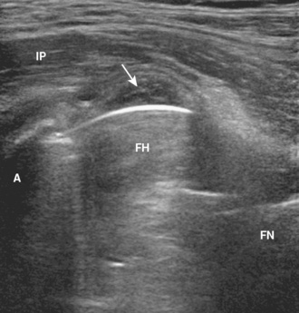
Percutaneous injection of the hip joint may be guided with fluoroscopy, CT, or ultrasound. The use of fluoroscopy is most common, and it can be completed in minutes with few complications. With the patient supine and oblique toward the opposite hip, the femoral artery is identified, and the skin directly over the femoral neck (lateral to the artery) is marked and prepared in typical sterile fashion. A 20-gauge spinal needle with a stylet is inserted into the femoral neck from an anterior or anterolateral approach. Needle-tip placement laterally near the femoral head–neck junction is usually successful, although any location along the femoral neck to the level of the intertrochanteric line is intra-articular (Figure 5-21). Because the needle tip may be located within the capsular reflection immediately adjacent to the bone, thus inhibiting low-resistance injection, minimal rotation of the needle or backing the needle out 1 mm during a test injection will assist with the finding of the joint recess. Before injecting the diagnostic or therapeutic agents, a test injection with iodinated contrast is used to confirm correct needle placement; the needle can then be repositioned as necessary with a repeat test injection of iodinated contrast. It is important to combine the diagnostic or therapeutic agents with iodinated contrast to visualize the structures that are being injected. The extension of diagnostic or therapeutic agents beyond the intended target (e.g., the filling of the iliopsoas bursa) must be reported. A diagnostic or therapeutic injection may be combined with dilute gadolinium for subsequent MR arthrography. The technique of hip injection with the use of CT is the same as described previously with the use fluoroscopy, in which a test injection of iodinated contrast is used before the injection of contrast with the diagnostic and therapeutic agents. CT is not typically used for hip injections, except for cases in which extensive heterotopic ossification may make fluoroscopic-guided injection difficult.
Bursa Injection
Both CT and ultrasound can be used to inject the bursae near the hip. Each imaging test is most accurate when there is distention of the bursa before the procedure, because the bursa is then visible and can be used as a target. With the use of sterile technique, a spinal needle is guided to the bursa for the injection, which will demonstrate low resistance to injection as compared with the surrounding soft tissues (Figure 5-22). A collapsed hip bursa is usually not identified during CT or ultrasound, which makes the injection of a collapsed bursa near the hip very difficult and most times unsuccessful. In this scenario, the needle is guided to where the bursa should be located, and test injections of an anesthetic agent are used while the needle is repositioned until the low resistance and distention of a bursa are found. If a bursa is not located, many times the area around the bursa is infiltrated with the agent, and this is noted in the procedural report. Fluoroscopy has also been described for the injection of the iliopsoas bursa, although ultrasound has the advantage of direct visualization of the bursa.
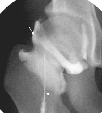
Peritendinous Injection
In the setting of snapping hip syndrome, the soft tissues between the snapping tendon or muscle and the adjacent bone may be injected. Ultrasound is ideal for this procedure, because, unlike CT, it allows for real-time imaging during needle positioning and for the targeting of soft tissues between the snapping structure and the bone, which is difficult with fluoroscopy. During ultrasound, if a bursa is identified, this can be the target of the injection. If a bursa is not visualized and not found during test injections, the tissues between the snapping structure and the bone are targeted. Injection for a snapping iliopsoas tendon under ultrasound guidance is completed in the axial plane, with the spinal needle entering from lateral to medial. The needle tip is placed between the iliopsoas tendon and the adjacent iliopectineal eminence, and the diagnostic and therapeutic agents are injected (Figure 5-23). During injection, fluid will be demonstrated to be pooling between the iliopsoas tendon and the ilium. It is important to inject around a tendon and to not place corticosteroids within the tendon because of the theoretic risk of tendon rupture. It is also important to avoid the injection of other structures (e.g., the hip joint), because this would create confusion with regard to the anatomic origin of symptoms and limit the effectiveness of diagnostic injection. Therapeutic injection around the iliopsoas tendon has been described for the treatment of impingement after total hip arthroplasty. With regard to a snapping iliotibial tract or gluteus maximus over the greater trochanter, ultrasound guidance is similarly used to inject the soft tissues between the snapping structure and the adjacent bone, including a bursa, if present.
Adler R.S., Buly R., Ambrose R., et al. Diagnostic and therapeutic use of sonography-guided iliopsoas peritendinous injections. AJR Am J Roentgenol.. 2005;185:940-943.
Amis E.S.Jr, Butler P.F., Applegate K.E., et al. American College of Radiology white paper on radiation dose in medicine. J Am Coll Radiol.. 2007;4:272-284.
Anda S., Terjesen T., Kvistad K.A. Computed tomography measurements of the acetabulum in adult dysplastic hips: which level is appropriate? Skeletal Radiol.. 1991;20:267-271.
Assoun J., Richardi G., Railhac J.J., et al. Osteoid osteoma: MR imaging versus CT. Radiology. 1994;191:217-223.
Beall D.P., Sweet C.F., Martin H.D., et al. Imaging findings of femoroacetabular impingement syndrome. Skeletal Radiol.. 2005;34:691-701.
Bianchi S., Martinoli C., Keller A., et al. Giant iliopsoas bursitis: sonographic findings with magnetic resonance correlations. J Clin Ultrasound. 2002;30:437-441.
Blankenbaker D.G., De Smet A.A., Keene J.S. Sonography of the iliopsoas tendon and injection of the iliopsoas bursa for diagnosis and management of the painful snapping hip. Skeletal Radiol.. 2006;35:565-571.
Carson B.W., Wong A. Ultrasonographic guidance for injections of local steroids in the native hip. J Ultrasound Med.. 1999;18:159-160.
The authors describe the use of ultrasound for guidance of steroid injection into the hip joint..
Choi Y.S., Lee S.M., Song B.Y., et al. Dynamic sonography of external snapping hip syndrome. J Ultrasound Med.. 2002;21:753-758.
Cody D.D., Mahesh M. AAPM/RSNA physics tutorial for residents: technologic advances in multidetector CT with a focus on cardiac imaging. Radiographics. 2007;27:1829-1837.
The authors review the development, radiation issues, and technical aspects of multidetector CT..
Cyteval C., Hamm V., Sarrabere M.P., et al. Painful infection at the site of hip prosthesis: CT imaging. Radiology. 2002;224:477-483.
Durkee N.J., Jacobson J., Jamadar D., et al. Classification of common acetabular fractures: radiographic and CT appearances. AJR Am J Roentgenol.. 2006;187:915-925.
Fairbairn K.J., Mulligan M.E., Murphey M.D., et al. Gas bubbles in the hip joint on CT: an indication of recent dislocation. AJR Am J Roentgenol.. 1995;164:931-934.
Feldman F., Staron R.B. MRI of seemingly isolated greater trochanteric fractures. AJR Am J Roentgenol.. 2004;183:323-329.
Flohr T.G., Schaller S., Stierstorfer K., et al. Multi-detector row CT systems and image-reconstruction techniques. Radiology. 2005;235:756-773.
Greenspan A. Bone island (enostosis): current concept—a review. Skeletal Radiol.. 1995;24:111-115.
Harcke H.T. Screening newborns for developmental dysplasia of the hip: the role of sonography. AJR Am J Roentgenol.. 1994;162:395-397.
The author proposes an ultrasound screening protocol for diagnosis of developmental hip dysplasia..
Jacobson J.A., van Holsbeeck M.T. Musculoskeletal ultrasonography. Orthop Clin North Am.. 1998;29:135-167.
The authors review musculoskeletal applications of ultrasound..
Kassarjian A., Yoon L.S., Belzile E., et al. Triad of MR arthrographic findings in patients with cam-type femoroacetabular impingement. Radiology. 2005;236:588-592.
Kim W.Y., Hutchinson C.E., Andrew J.G., et al. The relationship between acetabular retroversion and osteoarthritis of the hip. J Bone Joint Surg Br.. 2006;88:727-729.
Kitamura N., Pappedemos P.C., Duffy P.R3rd, et al. The value of anteroposterior pelvic radiographs for evaluating pelvic osteolysis. Clin Orthop Relat Res.. 2006;453:239-245.
Koski J.M., Anttila P.J., Isomaki H.A. Ultrasonography of the adult hip joint. Scand J Rheumatol.. 1989;18:113-117.
Leunig M., Beck M., Kalhor M., et al. Fibrocystic changes at anterosuperior femoral neck: prevalence in hips with femoroacetabular impingement. Radiology. 2005;236:237-246.
Lubovsky O., Liebergall M., Mattan Y., et al. Early diagnosis of occult hip fractures: MRI versus CT scan. Injury. 2005;36:788-792.
Mahesh M. Search for isotropic resolution in CT from conventional through multiple-row detector. Radiographics. 2002;22:949-962.
Murphey M.D., Vidal J.A., Fanburg-Smith J.C., et al. Imaging of synovial chondromatosis with radiologic-pathologic correlation. Radiographics. 2007;27:1465-1488.
Nishii T., Tanaka H., Nakanishi K., et al. Fat-suppressed 3D spoiled gradient-echo MRI and MDCT arthrography of articular cartilage in patients with hip dysplasia. AJR Am J Roentgenol.. 2005;185:379-385.
Nishii T., Tanaka H., Sugano N., et al. Disorders of acetabular labrum and articular cartilage in hip dysplasia: evaluation using isotropic high-resolutional CT arthrography with sequential radial reformation. Osteoarthritis Cartilage. 2007;15:251-257.
Park J.S., Ryu K.N., Hong H.P., et al. Focal osteolysis in total hip replacement: CT findings. Skeletal Radiol.. 2004;33:632-640.
Pateder D.B., Hungerford M.W. Use of fluoroscopically guided intra-articular hip injection in differentiating the pain source in concomitant hip and lumbar spine arthritis. Am J Orthop.. 2007;36:591-593.
Pelsser V., Cardinal E., Hobden R., et al. Extraarticular snapping hip: sonographic findings. AJR Am J Roentgenol.. 2001;176:67-73.
Pfirrmann C.W., Chung C.B., Theumann N.H., et al. Greater trochanter of the hip: attachment of the abductor mechanism and a complex of three bursae—MR imaging and MR bursography in cadavers and MR imaging in asymptomatic volunteers. Radiology. 2001;221:469-477.
Pourbagher M.A., Ozalay M., Pourbagher A. Accuracy and outcome of sonographically guided intra-articular sodium hyaluronate injections in patients with osteoarthritis of the hip. J Ultrasound Med.. 2005;24:1391-1395.
Rezig R., Copercini M., Montet X., et al. Ultrasound diagnosis of anterior iliopsoas impingement in total hip replacement. Skeletal Radiol.. 2004;33:112-116.
Robben S.G., Lequin M.H., Diepstraten A.F., et al. Anterior joint capsule of the normal hip and in children with transient synovitis: US study with anatomic and histologic correlation. Radiology. 1999;210:499-507.
Rosenthal D.I., Hornicek F.J., Torriani M., et al. Osteoid osteoma: percutaneous treatment with radiofrequency energy. Radiology. 2003;229:171-175.
Rydberg J., Liang Y., Teague S.D. Fundamentals of multichannel CT. Semin Musculoskelet Radiol.. 2004;8:137-146.
Strouse P.J., DiPietro M.A., Adler R.S. Pediatric hip effusions: evaluation with power Doppler sonography. Radiology. 1998;206:731-735.
Tallroth K., Lepisto J. Computed tomography measurement of acetabular dimensions: normal values for correction of dysplasia. Acta Orthop.. 2006;77:598-602.
Tehranzadeh J., Mossop E.P., Golshan-Momeni M. Therapeutic arthrography and bursography. Orthop Clin North Am.. 2006;37:393-408.
van Holsbeeck M.T., Eyler W.R., Sherman L.S., et al. Detection of infection in loosened hip prostheses: efficacy of sonography. AJR Am J Roentgenol.. 1994;163:381-384.
Wank R., Miller T.T., Shapiro J.F. Sonographically guided injection of anesthetic for iliopsoas tendinopathy after total hip arthroplasty. J Clin Ultrasound. 2004;32:354-357.
Weybright P.N., Jacobson J.A., Murry K.H., et al. Limited effectiveness of sonography in revealing hip joint effusion: preliminary results in 21 adult patients with native and postoperative hips. AJR Am J Roentgenol.. 2003;181:215-218.
Wines A.P., McNicol D. Computed tomography measurement of the accuracy of component version in total hip arthroplasty. J Arthroplasty. 2006;21:696-701.