[level-membership-for-orthopaedics-category]
CHAPTER 16 Complications of Locked Volar Plates
Volar plating with locked plates has dramatically reshaped the treatment of distal radius fractures. Along with any new technique come new complications, and locked volar plating is no exception. Complications of locked volar plating reported in the literature, at national and international presentations, in online discussion forums, in my personal cases, and in cases submitted for review to me have included:
Analysis of Complications
Tendon Irritation or Rupture from Pastpointing of Distal Screws
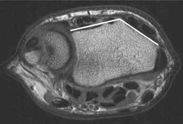
The dorsal cortex of the distal radius can be thought of as being composed of two surfaces, one radial and one ulnar to Lister’s tubercle. In the MR image shown in Figure 16-1 the two surfaces form a dihedral angle of approximately 140 degrees (see also Fig. 16-3), neither of which is parallel to the plane of a lateral radiograph. Therefore, the lateral radiograph will not profile either of the dorsal distal radial surfaces. Even if the profile of Lister’s tubercle is ignored, a lateral view of the distal radius will not be able to determine if the screw is extending beyond the dorsal cortex. This brings up several additional points.
The second point is that extensor tendons are less than 1 mm away from the dorsal cortex, separated from it by only a thin layer of periosteum. Pastpointing by only 1 mm will bring the screw into contact with the tendons. The earliest locked volar plates used standard orthopaedic screws. Their cutting flutes are on the order of 2 to 3 mm and are particularly dangerous. Many of the current generation of locked volar plates use custom distal locking screws, with a taper on the leading end on the order of 1 mm and much smaller cutting flutes. Traditional orthopaedic practice has been to have the screw pastpoint beyond the cutting flutes and/or screw tip taper to obtain optimal purchase on the far cortex. This practice in locked volar plating will bring the screw tip into contact with the extensor tendons. Even screws designed without a formal cutting flute will have a tapering thread, to start the thread into the bone. This leading edge of the thread can be problematic if it comes in contact with the tendons, which are forced against the dorsal cortex whenever the patient performs simultaneous wrist flexion and finger extension.
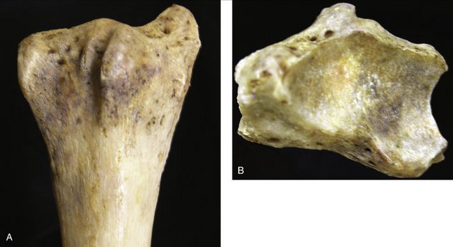
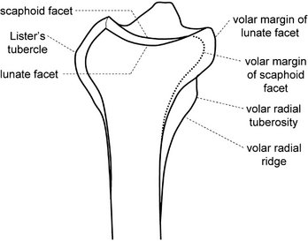
The third point, returning to an analysis of the distal radial anatomy and the lateral radiograph, is that even oblique views of the distal radius, such as obtained with intraoperative mini-fluoroscopy, cannot easily define the location of the dorsal cortex, because some tendons, particularly the extensor pollicis longus (EPL), lie in a slight indentation in the dorsal cortex (Fig. 16-2).
A fourth point is that there is no need to attempt to place the screws beyond or even close to the dorsal cortex. As observed earlier, the “distal cortex” is the subchondral bone. An examination of the lateral radiograph (see Fig. 16-8, later) shows that the subchondral bone stops several millimeters shy of the dorsal cortex. A screw can fully support the subchondral bone and yet stop 2 to 4 mm short of the dorsal cortex.
Case Examples
A 65-year-old woman fell and sustained a distal radius fracture. A locked volar plate was placed and intraoperative fluoroscopy indicated proper distal screw placement: just below the subchondral bone, out of the joint, and screw tips just below the dorsal cortex. Plain films were taken (Fig. 16-3A) and demonstrated a slight ulnar placement of the plate but good purchase on the dorsal ulnar corner and adequate purchase of the radial styloid on the posteroanterior view and good placement of the distal screws—just below the subchondral bone, out of the joint, and screw tips just below the dorsal cortex—on the lateral facet view.
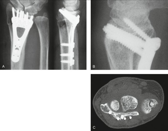
Follow-up plain films in the office, probably with a slightly different rotation, indicated that the screw tips were just penetrating the dorsal cortex but seemed appropriate at the time on review by several orthopaedic surgeons (see Fig. 16-3B).
However, the patient complained about wrist stiffness and pain more than most patients. There was absolutely no localizing tenderness along the dorsal radius to suggest screw prominence, and there was no irritation with finger range of motion. After several visits without improvement in symptoms or change in the physical examination to suggest screw prominence, computed tomography (CT) was performed (see Fig. 16-3C).
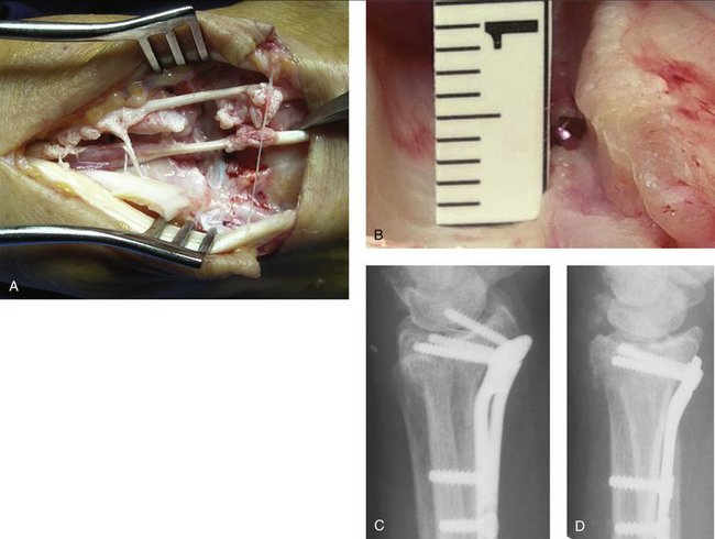
In a different case (Fig. 16-4A), note how much tendon damage was done by a screw in precisely the wrong place—directly below the EPL tendon, with only 1 mm of pastpointing (see Fig. 16-4B). Even minimal pastpointing can be disastrous if screws are positioned in the wrong place!
Placement of the Distal Screws into the Radiocarpal Joint
Clinical Pearl: To determine whether a screw will be into the joint, place a Kirschner wire (K-wire) through the drill guide locked into the screw hole in the plate. Remove the guide and plate, leaving the K-wire in place. Obtain a fluoroscopic view of the K-wire end-on. This view will precisely determine if the screw will be in the joint.
Figure 16-4C is a true lateral view, appearing to show penetration of the joint space by several screws and flagrant violation of the joint space by the radial styloid screw. However, the screw position resolves with a facet lateral view (Fig. 16-4D), with the majority of the screws nicely supporting the subchondral bone. A combination of the posteroanterior and the facet lateral views shows that the radial styloid screw is also out of the joint space.
Irritation or Rupture of Volar Tendons from Prominent Plates or Backing Out of Distal Screws
Some of the early locked volar plates and some of the first versions of current plates were more prominent than some of the other current generation plates. The Synthes volar 2.4/2.7 distal radius plate, colloquially called the “volar π plate,”* was a great innovation but had the disadvantages of both raised margins around the screw holes and sharp edges because the width needed to be trimmed to size. When selecting a locked volar plate, be sure that it is properly precontoured, low profile, and smooth on its distal margin.
Plate placement can also affect the tendons. If the plate is placed too distally, the flare of the volar rim of the joint will cause the plate to be prominent along its distal margin. The plate should not extend beyond the watershed line (yellow line in Fig. 16-5A), a term coined by Orbay that refers to the line at the highest (most volar) margin of the radius. This will be the part of the radius (or plate) that is closest to the flexor tendons and therefore at greatest risk of injuring them.
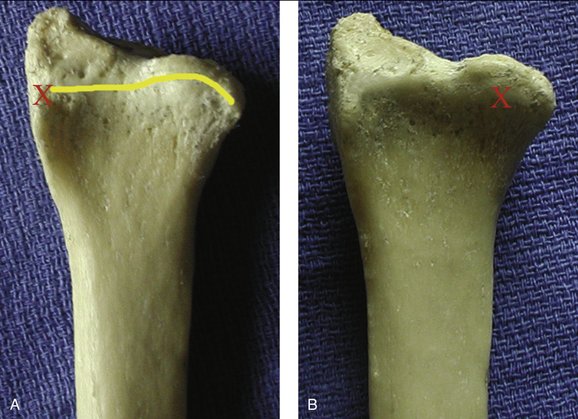
If the plate is placed too radially, a tuberosity called the volar radial tuberosity,* will raise up the radial margin. The tuberosity is easily palpated approximately 2 cm proximal to the volar tuberosity of the scaphoid (which is known to most surgeons in conjunction with the Watson test) and on the most radial aspect of the wrist. A plate placed too radially can become both clinically palpable (“Doc, is this bump supposed to be here? It wasn’t there before the surgery!”) and possibly a problem for the tendons (usually the flexor pollicis longus). If the plate is placed too ulnarly and has a flat profile across its distal margin, a bony feature called the lunate facet buttress will raise up the ulnar margin. The lunate facet buttress is a bony area just proximal to the lunate facet. The lunate facet projects several millimeters volarly more than the scaphoid facet (see Fig. 16-2B) and is supported by the lunate facet buttress, which varies in size from a millimeter to several millimeters. Some plates (Hand Innovations, Orthofix, and Acumed) are contoured to fit over the lunate facet buttress and still have the plate flat on the volar surface of the radius. The more distally a plate is placed and the larger the buttress is, the more relevant a contour in the plate becomes.
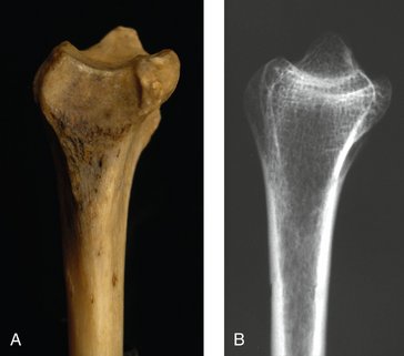
Figure 16-5A is a volar view of a radius, with the lighting coming from the left to highlight the volar radial tuberosity (indicated by the red “X”) and, extending proximally, the volar radial ridge. The yellow line represents the watershed line. Figure 16-5B is the same specimen, with the lighting coming from the top to highlight the lunate facet buttress (indicated by the red “X”).
Case Example
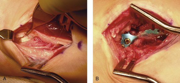
Damage was found to two tendons (Fig. 16-6) but no rupture. There was a hole in the pronator quadratus, and the plate was visible and felt to be prominent. The intraoperative assessment was that the properly precontoured plate did not fit the abnormal radius and that the screw holes felt “sharp” to evaluation. The plate was removed, and the symptoms resolved. (In addition, I have spoken to the manufacturer and confirmed that this was an early-generation design. The design has undergone a number of improvements, such that there is now less chance for screw hole “sharpness.”)
Case Example
A 61-year-old female bus driver fell in the schoolyard and sustained a volar Barton fracture (Fig. 16-7A, B). A volar π plate was placed to buttress the fracture (Fig. 16-7C, D).
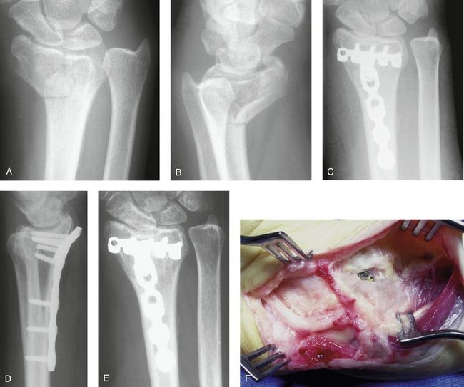
FIGURE 16-7 Posteroanterior (A) and lateral (B) radiographs of a volar Barton fracture. C, Posteroanterior radiograph after treatment with a volar π plate. D, Lateral postoperative radiograph. Note the incomplete reduction, with resulting prominence of the distal edge of the plate. Even without the incomplete reduction the plate was placed beyond the watershed line and would have been prominent. E, Posteroanterior radiograph obtained 6 years later. Note the subsidence of the scaphoid facet. F, Intraoperative view during plate removal. Note the hole in the dense scar tissue overlying the plate.
Six years after surgery she presented with the sudden onset of an inability to flex her thumb interphalangeal joint, wrist swelling, and wrist tenderness. Radiographs showed no progression of the subsidence of the scaphoid into the radius (see Fig. 16-7E) and resolution of the cystic degeneration. The plate continued to be prominent volarly.
The diagnosis was made of a flexor pollicis longus rupture due to rubbing on the distal edge of the prominent plate. At surgery, the plate was found to be covered by a dense layer of scar tissue, except at one point. The most radial distal screw (there was one empty hole to the radial side of this screw) was easily seen through a rent in the scar tissue (see Fig. 16-7F).
There seems to be an advantage to covering the plate with the pronator quadratus (PQ) to interpose the muscle between the plate and the flexor tendons. During the initial dissection, most surgeons incise the PQ distally at the edge of the muscle fibers. This line is referred to as the PQ line.* After plate placement, most surgeons repair the PQ muscle. However, the thinness of the fascia of the muscle makes this an exercise in futility, because the sutures typically rip out before the next layer is closed. One technique that has proved to be quite secure is to release the PQ during the original dissection not along the margin of the muscular fibers (the PQ line), but 1 to 2 mm beyond the PQ line, into the fibrous tissue proximal to the volar capsule. This fibrous tissue, termed the fibrous transition zone, has been determined in cadaveric dissections not to be part of the mobile volar wrist capsule (composed of the radioscaphoid, radiocapitate, long radiolunate, and short radiolunate ligaments) but to be immobile and attached to the distal margin of the radius. It is believed that incising the fibrous transition zone should not add unnecessarily to wrist capsular scarring or wrist joint stiffness. Continue the dissection radially 1 to 2 mm into the fibrous tissue at the base of the first dorsal compartment. If this is done there will be a 1- to 2-mm thick, strong margin along the edge of the PQ muscle. This margin will securely hold the sutures and the PQ will remain in place, serving as an interpositional layer between the plate and the flexor tendons.
Subsidence of Fragments and/or Dorsal Subluxation of the Carpus from Failure to Engage the Dorsal Ulnar Fragment
Case Example
A 20-year-old man fell from a mountain bike and sustained bilateral wrist injuries. Radiographs demonstrated bilateral distal radius fractures and a right scaphoid fracture. The left wrist is shown in Figure 16-8A.
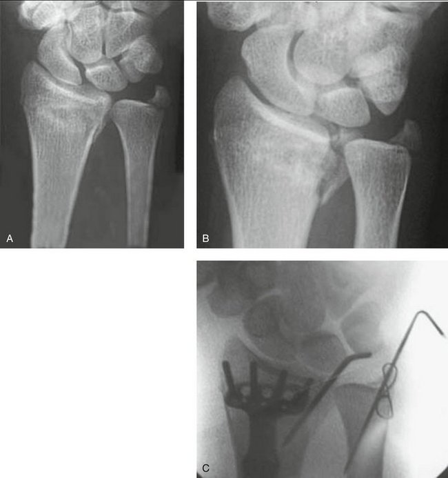
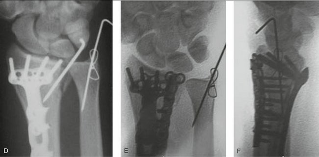
FIGURE 16-8 A, Posteroanterior radiograph of distal radius fracture. (The patient also has distal radius and scaphoid fractures on the opposite hand.) B, Oblique radiograph demonstrates the dorsal ulnar corner fracture. C, Slightly obliqued posteroanterior radiograph showing the lack of purchase of the dorsal ulnar corner by the plate and screws; it was supplemented with a Kirschner wire. The fracture appears reduced. D, Slightly obliqued posteroanterior radiograph at 1 week. Note the displacement of the fracture fragment. E and F, Posteroanterior and lateral radiographs after revision surgery. Note the fragment-specific plate on the dorsal ulnar corner of the radius.
The radiographs indicated a fracture of the dorsal ulnar corner, so oblique views were obtained to assess its displacement (see Fig. 16-8B). The oblique view much better demonstrated the size and displacement of the dorsal ulnar corner. The opposite wrist had a very similar distal radius fracture in addition to the scaphoid waist fracture. Open reduction and internal fixation was performed for all three fractures.
A locked volar plate was supplemented with a dorsal 0.062-inch K-wire to hold the left radius. Once the radius was fixed, DRUJ stability was assessed and found to be unstable. This was attributed to the ulnar styloid fracture. This was fixed with a 0.045-inch K-wire and figure-of-eight wire in a tension band configuration (see Fig. 16-8C). The patient was seen at 1 week and follow-up radiographs were obtained.
The follow-up views demonstrated displacement of the dorsal ulnar corner, in a manner identical to the original injury (see Fig. 16-8D). A critical review of the immediate postoperative films shows that the dorsal ulnar corner was not fixed with the volar plate and that the K-wire fixation was not stiff enough alone to resist the deforming forces. One could also speculate that the instability of the DRUJ was entirely or in part due to the dorsal ulnar corner rather than the ulnar styloid fracture. It was thought that the instability had a chance of progressive subsidence, and further fixation was required. (The opposite wrist had an identical subsidence and reoperation was also done on it.)
The patient was returned to the operating room where a dorsal plate was placed through a dorsal incision (see Fig. 16-8E). This reduction was maintained and at 1 year the patient had good motion with little to no pain.
Subsidence of Fragments and Volar Subluxation of the Carpus from Failure to Stabilize the Volar Rim of the Lunate Facet
Figure 16-9A is the lateral view of a dried radius from the ulnar side. The key point is that the lunate facet projects quite a bit volarly (see also Figs. 16-1 and 16-2B) and that the center of the facet is directly over the volar aspect of the radius. It is not over the center of the medullary canal. The load from the carpus places a force on the lunate facet that has a component that is distinctly volarly directed. This, combined with the extent of volar projection of the lunate facet, makes lunate rim fractures very unstable (Fig. 16-10).
No locked volar plate extends to the volar lip of the lunate facet. The one that comes the closest is the Synthes 2.4 LCP Volar Juxta-Articular Distal Radius Plate. Most designs do not want to extend that far past the watershed line and risk injuring the flexor tendons, and how far a plate should extend distally is controversial. However, in the case of a fracture of the volar lip of the lunate facet, some kind of stabilization is required and some violation of the watershed line is needed. Various techniques have been used or proposed, including using the Synthes Juxta-Articular plate, placing a standard plate more distally, using a fragment-specific approach, or using K-wires. The effectiveness of each approach depends on the fragment size, the technique used, and the actual shape of the implant. The Synthes Juxta-Articular plate or the fragment-specific approaches are probably the most common, but each has its limitations. The Synthes plate unnecessarily extends beyond the watershed line for the scaphoid facet, which does not need support. The fragment-specific approach is less stable and more complex to apply.
Inability to Remove a Plate/Screws Because of Bony Adherence to Titanium Implants
There have been reports of titanium screws being so firmly bonded to the bone that the heads shear off, the driver tip shears off, or the head strips out. Surgeons have had to resort to breaking the implants and burring off any projecting screw remnants. This point remains controversial. Some authors recommend the use of stainless steel implants to avoid bonding and screw breakage, and others claim that there is no chemical bonding between bone and titanium. It is interesting to observe the competing claims of two groups with very different agendas: the trauma companies deny that bonding to their titanium implants exists, whereas the total joint companies tout the strength of the bonding to their titanium implants. Many surface treatments, from polishing to chemical treatment or hydroxyapatite coating, have been tried to avoid or enhance bonding. The controversy does not seem to have a resolution at this time, and there does not seem to be a clear reason to avoid titanium locked volar plates. In the one case of late titanium plate removal in my experience, at 6 years after implantation (see case cited earlier involving a second-generation Synthes titanium plate [see Fig. 16-7F]), all screws were easily removed once the bony overgrowth covering the screw heads was removed.
Clinical Pearls
* The term “π plate” was never used by Synthes but was created by surgeons as more descriptive.
* These terms have been proposed by Jorge Orbay, Randy Bindra, and the author in a paper submitted to the Journal of Hand Surgery.
* These terms have been proposed by Jorge Orbay, Randy Bindra, and the author in a paper submitted to the Journal of Hand Surgery.
[/level-membership-for-orthopaedics-category][not-level-membership-for-orthopaedics-category]
CHAPTER 16 Complications of Locked Volar Plates
Volar plating with locked plates has dramatically reshaped the treatment of distal radius fractures. Along with any new technique come new complications, and locked volar plating is no exception. Complications of locked volar plating reported in the literature, at national and international presentations, in online discussion forums, in my personal cases, and in cases submitted for review to me have included:
Analysis of Complications
Tendon Irritation or Rupture from Pastpointing of Distal Screws
The dorsal cortex of the distal radius can be thought of as being composed of two surfaces, one radial and one ulnar to Lister’s tubercle. In the MR image shown in Figure 16-1 the two surfaces form a dihedral angle of approximately 140 degrees (see also Fig. 16-3), neither of which is parallel to the plane of a lateral radiograph. Therefore, the lateral radiograph will not profile either of the dorsal distal radial surfaces. Even if the profile of Lister’s tubercle is ignored, a lateral view of the distal radius will not be able to determine if the screw is extending beyond the dorsal cortex. This brings up several additional points.
The second point is that extensor tendons are less than 1 mm away from the dorsal cortex, separated from it by only a thin layer of periosteum. Pastpointing by only 1 mm will bring the screw into contact with the tendons. The earliest locked volar plates used standard orthopaedic screws. Their cutting flutes are on the order of 2 to 3 mm and are particularly dangerous. Many of the current generation of locked volar plates use custom distal locking screws, with a taper on the leading end on the order of 1 mm and much smaller cutting flutes. Traditional orthopaedic practice has been to have the screw pastpoint beyond the cutting flutes and/or screw tip taper to obtain optimal purchase on the far cortex. This practice in locked volar plating will bring the screw tip into contact with the extensor tendons. Even screws designed without a formal cutting flute will have a tapering thread, to start the thread into the bone. This leading edge of the thread can be problematic if it comes in contact with the tendons, which are forced against the dorsal cortex whenever the patient performs simultaneous wrist flexion and finger extension.
The third point, returning to an analysis of the distal radial anatomy and the lateral radiograph, is that even oblique views of the distal radius, such as obtained with intraoperative mini-fluoroscopy, cannot easily define the location of the dorsal cortex, because some tendons, particularly the extensor pollicis longus (EPL), lie in a slight indentation in the dorsal cortex (Fig. 16-2).
A fourth point is that there is no need to attempt to place the screws beyond or even close to the dorsal cortex. As observed earlier, the “distal cortex” is the subchondral bone. An examination of the lateral radiograph (see Fig. 16-8, later) shows that the subchondral bone stops several millimeters shy of the dorsal cortex. A screw can fully support the subchondral bone and yet stop 2 to 4 mm short of the dorsal cortex.
Case Examples
A 65-year-old woman fell and sustained a distal radius fracture. A locked volar plate was placed and intraoperative fluoroscopy indicated proper distal screw placement: just below the subchondral bone, out of the joint, and screw tips just below the dorsal cortex. Plain films were taken (Fig. 16-3A) and demonstrated a slight ulnar placement of the plate but good purchase on the dorsal ulnar corner and adequate purchase of the radial styloid on the posteroanterior view and good placement of the distal screws—just below the subchondral bone, out of the joint, and screw tips just below the dorsal cortex—on the lateral facet view.
Follow-up plain films in the office, probably with a slightly different rotation, indicated that the screw tips were just penetrating the dorsal cortex but seemed appropriate at the time on review by several orthopaedic surgeons (see Fig. 16-3B).
However, the patient complained about wrist stiffness and pain more than most patients. There was absolutely no localizing tenderness along the dorsal radius to suggest screw prominence, and there was no irritation with finger range of motion. After several visits without improvement in symptoms or change in the physical examination to suggest screw prominence, computed tomography (CT) was performed (see Fig. 16-3C).
In a different case (Fig. 16-4A), note how much tendon damage was done by a screw in precisely the wrong place—directly below the EPL tendon, with only 1 mm of pastpointing (see Fig. 16-4B). Even minimal pastpointing can be disastrous if screws are positioned in the wrong place!
