[level-membership-for-basic-science-category]
Clarification
Andrew M. Twitchell
Chapter contents
Key points
• Clarification can be achieved using either filtration or centrifugation techniques.
• Straining/sieving and impingement are the main mechanisms by which filtration occurs.
Introduction
Clarification is a term used to describe processes that involve the removal or separation of a solid from a fluid, or a fluid from another fluid. The term ‘fluid’ encompasses both liquids and gases. Clarification can be achieved using either filtration or centrifugation techniques, both of which are described in this chapter.
In pharmaceutical processing there are two main reasons for such processes:
Filtration
Types of filtration
Solid/fluid filtration
Solid/fluid filtration can be defined as the separation of an insoluble solid from a fluid by means of a porous medium that retains the solid but allows the fluid to pass. It is the most common type of filtration encountered during the manufacture of pharmaceutical products. Solid/fluid filtration may be further subdivided into two types, namely solid/liquid filtration and solid/gas filtration.
Solid/liquid filtration.
There are numerous applications of solid/liquid filtration in pharmaceutical processing, some of which are listed below:
Solid/gas filtration.
There are two main applications of solid/gas filtration in pharmaceutical processing. One of particular importance in manufacturing is the removal of suspended solid material from air in order to supply air of the required standard for either processing equipment or manufacturing areas. This includes the provision of air for equipment such as fluidized-bed processors (see Chapters 28 and 29), film-coating machinery (Chapter 32) and bottle-cleaning equipment, so that product appearance and quality are maintained. The use of suitable filters also enables the particulate contamination of air in manufacturing areas to be at an appropriate level for the product being manufactured; for example, air free from microorganisms can be supplied to areas where sterile products are being manufactured.
It is also often necessary to remove particulate matter generated during a manufacturing operation from the process air in order to prevent the material being vented to the atmosphere. Examples of this include filtering of exhaust air from fluidized-bed and coating processes.
Fluid/fluid filtration
Flavouring oils are sometimes added to liquid preparations in the form of a spirit, i.e. dissolved in alcohol. When these spirits are added to aqueous-based formulations some of the oil may come out of solution, giving the product a degree of turbidity. Removal of the oil droplets by passing them through an appropriate filter (a liquid/liquid filtration process) is used to produce the desired product appearance.
Compressed air is used in a number of pharmaceutical processes, e.g. film-coating spray guns (Chapter 32), bottle-cleaning equipment and fluid energy mills (Chapter 10). Before use, the compressed air needs to be filtered to ensure that any entrained oil or water droplets are removed. This is an example of a fluid/gas filtration process.
Mechanisms of filtration
The mechanisms by which material may be retained by a filter medium (i.e. the surface on or in which material is deposited) are discussed below.
Straining/sieving
If the pores in the filter medium through which the fluid is flowing are smaller than the material that is required to be removed, the material will be retained. Filtration occurs on the surface of the filter in this case, and therefore the filter can be very thin (typically around 100 µm). Filter media of this type are referred to as membrane filters. Because filtration occurs on the surface there is a tendency for them to become blocked unless the filter is carefully designed (see later). Filters employing the straining mechanism are used where the contaminant level is low or small volumes need to be filtered. Examples of the use of membrane filters include the removal of bacteria and fibres from parenteral preparations.
Impingement
As a flowing fluid approaches and passes an object, for example a filter fibre, the fluid flow pattern is disturbed, as shown in Figure 25.1. Suspended solids may, however, have sufficient momentum so that they do not follow the fluid path but impinge on the filter fibre and are retained, owing to attractive forces between the particle and the fibre. Where the pores between filter fibres are larger than the material being removed, some particles may follow the fluid streamlines and miss the fibre, this being more likely if the particles are small (owing to their lower momentum) and as the distance from the centre of the fibre towards which they approach increases. To ensure the removal of all unwanted material, filter media using the impingement mechanism must be sufficiently thick so that material not trapped by the first fibre in its path is removed by a subsequent one. These types of filter are therefore referred to as depth filters. The fluid should flow through the filter medium in a streamlined manner to ensure the filter works effectively, as turbulent flow may carry the particles past the fibres. Depth filters are the main type of filter used for removing material from gases.
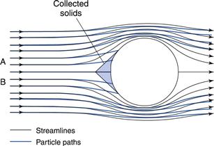
Fig. 25.1 Filtration by impingement.
Attractive forces
Electrostatic and other surface forces may exert sufficient hold on the particles to attract and retain them on the filter medium (as occurs during the impingement mechanism).
Air can be freed from dust particles in an electrostatic precipitator by passing the air between highly charged surfaces, which attract the dust particles.
Autofiltration
Autofiltration is the term used to describe the situation when filtered material (termed the filter cake) acts as its own filter medium. This mechanism is used by the metafilter which is covered later in this chapter.
Factors affecting the rate of filtration
The filtration process chosen must remove the required ‘contaminants’ or product but must also do so at an acceptably fast rate to ensure that the manufacturing process can be carried out economically. The laboratory Buchner funnel and flask (Fig. 25.2) is a convenient filter that can be used to illustrate the factors that influence the rate at which a product can be filtered. This filter is used for solid/liquid filtration processes but the same basic principles are valid whatever filtration process is being evaluated.
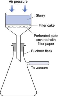
Fig. 25.2 Buchner funnel and vacuum flask.
The rate of filtration (volume of filtered material (V, m3) obtained in unit time (t, s) ) depends on the following factors:
• the viscosity of the fluid passing through the filter, i.e. the filtrate (µ, Pa s). A viscous fluid will filter more slowly than a mobile one owing to the greater resistance to movement offered by more viscous fluids (see Chapter 6)
Darcy’s equation
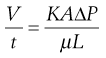
The above factors are combined in the Darcy equation:
 (25.1)
In this equation the driving force for this particular ‘rate process’ is the pressure difference across the filter, and the resistance to the process is a function of the properties of the filter bed, its thickness and the viscosity of the filtrate. The contribution to resistance to filtration from the filter medium is usually small compared to that of the filter cake, and can often be neglected in calculations.
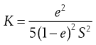
The proportionality constant K (m2) expresses the permeability of the filter medium and cake and will increase as the porosity of the bed increases. It is clearly desirable that K should be large in order to maximize the filtration rate. If K is taken to represent the permeability of the cake, it can be shown that K is given by:
 (25.2)
where e is the porosity of the cake and S is the surface area of the particles comprising the cake. If the solid material is one that forms an impermeable cake, the filtration rate may be improved by adding a filter aid (discussed later), which aids the formation of open porous cakes.
Methods used to increase filtration rate
Darcy’s equation can be used to determine ways in which the filtration rate can be increased or controlled in practice. These are now discussed.
Increase the area available for filtration.
The total volume of filtrate flowing through the filter will be directly proportional to the area of the filter, and hence the rate of filtration can be increased by using either larger filters or a number of small units in parallel. Both of these approaches will also distribute the cake over a larger area and thus decrease the value of L, thereby further increasing the filtration rate.
Increase the pressure difference across the filter cake.
The simplest filters, e.g. a laboratory filter funnel, use the gravitational force of the liquid ‘head’ to provide the driving force for filtration. Often this driving force is too low for an acceptably fast filtration rate and there is a requirement to increase it. If a vacuum is ‘pulled’ on the far side of the filter medium (see Fig. 25.1) then the pressure difference can be increased up to atmospheric pressure, i.e. approximately 100 kPa or 1 bar. In practice, however, it will be less, as liquids will boil in the collecting vessel if the pressure is reduced to too low a value. Despite the limited pressure difference generated, vacuum filtration is used in the laboratory where there are safety advantages in using glassware, because if the glassware is damaged it will implode rather than explode. One important industrial filter, the rotary vacuum filter, also utilizes a vacuum; this is described later in this chapter.
With industrial-scale liquid filtration, commonly used means of obtaining a high-pressure difference are either pumping the material to be filtered into the filter using a suitable pump, or using a pressurized vessel to drive the liquid through the filter. Most industrial filters have a positive-pressure feed, the pressure used being limited only by the pump capacity and the ability of the filter to withstand the high-pressure stress. Pressures up to 1.5 MPa (15 bar) are commonly used.
Although increasing the ΔP value in the absence of any other changes will cause a proportional increase in filtration rate, care needs to be taken to ensure that a phenomenon known as cake compression does not occur. Too high an applied pressure may cause the particles making up the cake to deform and therefore decrease the voidage (bed porosity). It can be seen from Equation 25.2 that small decreases in the value of the porosity (e) lead to large decreases in cake permeability (K), and therefore in the filtration rate. The effect of decreasing K greatly outweighs any increase in filtration rate arising from a thinner cake. There is also a danger of ‘blinding’ the filter medium at high pressures by forcing particles into it. This is most likely in the early stages before a continuous layer of cake has formed. As a general rule, filtration should start at moderate pressure, which can be increased as filtration proceeds and the cake thickness builds up.
Decrease the filtrate viscosity.
The flow through a filter cake can be considered as the total flow through a large number of capillaries formed by the voids between the particles of the cake. The rate of flow through each capillary is governed by Poiseuille’s Law, which is a mathematical relationship that includes viscosity as a factor contributing to the resistance to flow. To increase the filtration rate, the viscosity of the filtrate can be reduced in most cases by heating the formulation to be filtered. Many industrial filters, e.g. the metafilter, can be fitted with a steam jacket which can control temperature and hence viscosity. Care needs to be taken with this approach, however, when filtering formulations containing volatile components, or if components are thermolabile. In such cases, dilution of the formulation with water may be an alternative means of reducing the viscosity providing that the increase in filtration rate exceeds the effect of increasing the total volume to be filtered.
Decrease the thickness of the filter cake.
Darcy’s equation (Eqn 25.1) shows that the filtration rate falls off as the cake increases in thickness. This effect is commonly observed when filtering in the laboratory using filter paper in a funnel. In some cases, if the cake is allowed to build up the process slows to an unacceptable rate, or may almost stop. In these situations it may be necessary to remove the cake periodically or to maintain it at a constant thickness, as occurs for example with the rotary drum filter. As previously mentioned, the cake thickness can be kept lower by using a larger filter area.
Increase the permeability of the cake.
One way of increasing the permeability of the cake is to include filter aids. A filter aid is a material that, when included in the formulation to be filtered, forms a cake of a more open, porous nature and thus increases the K value in Darcy’s equation. In addition, it may reduce the compressibility of the cake and/or prevent the filtered material blocking the filter medium. Filter aids that are used include diatomite (a form of diatomaceous earth) and perlite (a type of naturally occurring volcanic glass) which has been used in the filtration of, for example, penicillin and streptomycin. The use of filter aids is obviously not appropriate if the filtered material is the intended end product.
Filtration equipment
The filtration equipment described in this chapter is that used for filtering liquids. Equipment for filtering gases (mainly air) is also available.
Equipment selection
Ideally the equipment chosen should allow a fast filtration rate to minimize production costs, be cheap to buy and use, be easily cleaned and resistant to corrosion, and be capable of filtering large volumes of product before the filter needs stripping down for cleaning or replacing.
There are a number of product-related factors that should be considered when selecting a filter for a particular process. These include:
• the operating pressure needed. This is important in governing the filtration rate (Eqn 25.1) and influences whether a vacuum filter (where the pressure difference is limited to approximately 100 kPa) is appropriate. High operating pressures require that the equipment is of sufficient strength and that appropriate safe operating procedures are adopted
Industrial filtration equipment
Filters for liquid products may be classified by the method used to drive the filtrate through the filter medium. Filters can be organized into three classes, namely gravity, vacuum and pressure filters.
Gravity filters
Filters that rely solely on gravity generate only low operating pressures and therefore use on a large scale is limited. Gravity filters are, however, simple and cheap, and are frequently used in laboratory filtration where volumes are small and a low filtration rate is relatively unimportant.
Vacuum filters
The rotary vacuum filter.
In large-scale filtration, continuous operation is often desirable and this may be difficult to achieve when it is necessary to filter slurries containing a high proportion of solids. The rotary vacuum filter is continuous in operation and has a system for removing the cake so that it can be run for long periods handling concentrated slurries. A rotary drum filter is shown in Figure 25.3. It can be visualized as two concentric cylinders with the annular space between them divided into a number of septa by radial partitions. The outer cylinder is perforated and covered with a filter cloth. Each septum has a radial connection to a complicated rotating valve whose function is to perform the sequence of operations listed in Table 25.1.
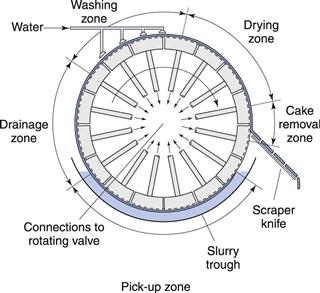
Fig. 25.3 Rotary drum filter.
The cylinder rotates slowly in the slurry, which is kept agitated, and a vacuum applied to the segments draws filtrate into the septa, depositing cake on the filter cloth. When the deposited cake leaves the slurry bath, vacuum is maintained to draw air through the cake, thus aiding liquid removal. This is followed by washing and then further drainage in the drying zone. The cake is removed by the scraper blade aided by compressed air forced into the septa. It is the function of the rotary valve to direct these services into each septum when required.
Rotary filters can be up to 2 m in diameter and 3.5 m in length, with a filtration area of around 20 m2. The drum rotates slowly, typically between 10 and 60 revolutions per hour. Cake compression rollers are often fitted to improve the efficiency of washing and draining if the cake on the drum becomes cracked. Difficult solids, which tend to block the filter cloth, necessitate a preliminary precoat of a filter aid to be deposited on the cloth prior to filtration of the slurry. During the actual filtration, the scraper knife is set to move slowly inwards, removing the blocked outer layer of the filter aid and exposing fresh surface.
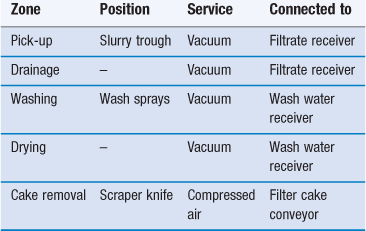
If removal of the cake presents problems, a string discharge filter may be employed. This is useful for filtration of the fermentation liquor in the manufacture of antibiotics, when a felt-like cake of mould mycelia must be removed. The filter cloth in this case has a number of bands passing round the drum and over two additional small rollers, as shown in Figure 25.4. In operation, the bands lift the cake off the filter medium. The cake is broken by the sharp bend over the rollers and collected, and the bands return to the drum.
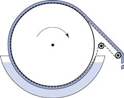
Fig. 25.4 String discharge rotary drum filter.
The advantages of the industrial rotary vacuum filter can be summarized as follows:
• It is automatic and continuous in operation, so that labour costs are low.
Disadvantages of the rotary vacuum filter include the following:
Small rotary vacuum filter units with a drum approximately 120 mm long and 75 mm diameter are also available. These are simpler in construction than the larger industrial-type units as they do not have a cake-washing facility. They have disposable filter drums and can filter batches from around 100 to 700 litres at a rate of 1–2 litres/minute.
The rotary filter is most suitable for continuous operation on large quantities of slurry, especially if the slurry contains considerable amounts of solids, that is, in the range 15–30%.
Examples of pharmaceutical applications include the collection of calcium carbonate, magnesium carbonate and starch, and the separation of the mycelia from the fermentation liquor in the manufacture of antibiotics.
Pressure filters
Pressure filters feed the product to the filter at a pressure greater than that which would arise from gravity alone. This is the most common type of filter used in the processing of pharmaceutical products.
The metafilter.
In its simplest form, the metafilter consists of a grooved drainage rod on which is packed a series of metal rings. These rings, usually made of stainless steel, are about 15 mm inside diameter, 22 mm outside diameter and 0.8 mm in thickness, with a number of semicircular projections on one surface (Fig. 25.5). The height of the projections and the shape of the section of the ring are such that when the rings are packed together and tightened on the drainage rod, channels are formed that taper from about 250 µm down to 25 µm. One or more of these packs is mounted in a vessel and the filter operated by pumping in the slurry under pressure.
In this form the metafilter can be used for separating coarse particles but for finer particles, a bed of a suitable material (such as a filter aid) is first built up over the rings by recirculating a filter aid suspension. The pack of rings, therefore, serves essentially as a base on which the true filter medium is supported.
The advantages of the metafilter can be summarized as follows:
The small surface area of the metafilter restricts the amount of solid that can be collected. This, together with the ability to separate very fine particles, means that the metafilter is used almost exclusively for clarifying liquids where the contaminant level is low. Furthermore, the strength of the metafilter permits the use of high pressures (up to 1.5 MPa, 15 bar), making the method suitable for viscous liquids.
Specific examples of pharmaceutical uses include the clarification of syrups, injection solutions and intermediates such as insulin liquors.
Cartridge filters.
Cartridge filters are now commonly used in the preparation of pharmaceutical products, as they possess a very large filtration area in a small unit and are easy and relatively cheap to operate. In simple form, they consist of a cylindrical cartridge containing highly pleated material (e.g. PTFE or nylon) or ‘string-wound’ material (i.e. wound like a ball of string). This cartridge then fits in a metal supporting cylinder and the product is pumped under pressure into one end of the cylinder surrounding the filter cartridge. The filtrate is forced through the filter cartridge from the periphery to the inner hollow core, from where it exits through the other end of the support cylinder. The filter cartridges are often disposable and are good for applications where there is a low contaminant level, e.g. during the filtration of liquid products as they are filled into bottles.
Cross-flow microfiltration.
It is possible to form membrane filters within ‘hollow fibres’. The membrane, which may consist of polysulphone, acrylonitrile or polyamide, is laid down within a fibre which forms a rigid porous outer support (Fig. 25.6). The lumen of each fibre is small, typically 1–2 µm. However, a large number of fibres can be contained in a surrounding shell to form a cartridge which may have an effective filtration area of over 2 m2.
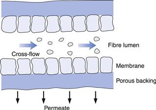
In use, the liquid to be treated is pumped through the cartridge in a circulatory system, so that it passes through many times. The filtrate, which in this technique is often called the ‘permeate’, flows radially through the membrane and porous support. The great advantage of this mode of operation is that the high fluid velocity and turbulence minimize blocking of the membranes. Fresh liquid enters the system from a reservoir as filtration proceeds. Because the fluid flow is across the surface, rather than at right angles, this technique is known as cross-flow microfiltration.
The method has been used for fractionation of biological products by first using a filter of pore size sufficient to let through all the molecules equal to or smaller in size than those required, and then passing the permeate through a second filter that will retain the required molecules while passing smaller unwanted molecules. Blood plasma can be processed to remove alcohol and water and prepare concentrated purified albumin using this method. The process has also been used for the recovery of antibiotics from fermentation media.
Centrifugation
Centrifugal force can be used either to provide the driving force (ΔP) for the filtration process (refer to Darcy’s equation above, Eqn 25.1) or to replace the gravitational force in sedimentation processes (refer to Stokes’ Law, Chapter 5 and Chapter 6). Centrifuges are often used in the laboratory to separate solid material from a liquid, the solid typically forming a ‘plug’ at the bottom of the test tube at the end of the process.
Principles of centrifugation
If a particle (mass = m, kg) spins in a centrifuge (radius r, m) at a velocity (v, m s−1) then the centrifugal force (F, N) acting on the particle equals mv2/r. The same particle experiences gravitational force (G, N) equal to m × g (where g = the gravitational constant).
The centrifugal effect (C) is the ratio of these two forces, so C = F/G, i.e. C indicates how many times greater F is than G. Therefore, C = v2/g r. If the rotational velocity is taken to be π d n, where n is rotation speed (s−1) and d is the diameter of rotation (m), then C = 2.01 d n2.
To increase the centrifugal effect, it is more efficient to increase the centrifuge speed than use a larger diameter at the same speed. Larger centrifuges generate greater pressures on the centrifuge wall for the same value of C, so are more costly to make.
Industrial centrifuges
Two main types of centrifuge are used to achieve separation on an industrial scale: those using perforated baskets, which perform a filtration-type operation (like a spin-dryer), and those with a solid-walled vessel, where particles sediment towards the wall under the influence of the centrifugal force.
Perforated-basket centrifuges (centrifugal filters)
A diagram of a perforated-basket centrifuge is shown in Figure 25.7. It consists of a stainless steel perforated basket (typically 1–2 m in diameter) lined with a filter cloth. The basket rotates at a speed which is typically <25 s−1, higher speeds tending to stress the basket excessively. The product enters centrally and is thrown outwards by centrifugal force and held against the filter cloth. The filtrate is forced through the cloth and removed via the liquid outlet; the solid material is retained on the cloth. The cake can be washed, if required, by spraying water into the centrifuge.
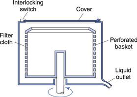
Fig. 25.7 Centrifugal dewatering filter.
The centrifugal filter has been used for separating crystalline materials from the preparation liquor, e.g. in the preparation of drug crystals, and for removing precipitated proteins from, for example, insulin. It has the advantages of being compact and efficient, a 1 m diameter centrifuge being able to process about 200 kg in 10 minutes. It can also handle concentrated slurries which might block other filters. The spinning action gives a product with a low moisture content (typically around 2% w/w) which saves energy during subsequent drying.
The centrifuge described above is operated batch-wise, but continuous centrifuges are available for large-scale work. These have a means for automatic discharge of the cake from a basket, which rotates around a horizontal axis in contrast to the vertical axis. Most of the energy required to run a centrifuge is used to bring it up to the operating speed and little more is needed to maintain that speed. Continuous centrifuges are therefore cheaper to run but the initial cost is considerably higher.
Tubular-bowl centrifuges (centrifugal sedimenters)
These consist of a cylindrical ‘bowl’, typically around 100 mm in diameter and 1 m long, that rotates at a high speed, 300–1000 s−1. The product enters at the bottom and centrifugal force causes solids to be deposited on the wall as it passes up the bowl, the clear liquid overflowing from the top (Fig. 25.8). This type of centrifuge can also be adapted to separate immiscible liquids. The inlet rate needs to be controlled so that there is sufficient time for sedimentation to occur before the product leaves the bowl.
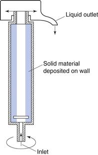
Fig. 25.8 Tubular-bowl centrifuge.
The uses of centrifugal sedimenters include:
• the removal of very small particles
• the removal of solids that are compressible or ‘slimy’ and which easily block filter media
• the separation of blood plasma from whole blood (a C of approximately 3000 is required)
These centrifuges are compact, have a high separating efficiency and are good for separating ‘difficult’ solids. However, they have a limited capacity and are complicated to construct in order to achieve the required speed and minimize vibration.
Bibliography
1. Jornitz MW, Meltzer TH. Filtration and Purification in the Biopharmaceutical Industry. London: Informa Healthcare; 2008.
2. Sparks T. Solid-liquid filtration. Oxford, UK: Butterworth Heinemann; 2012.
3. Sutherland K. Filters and Filtration Handbook. London: Elsevier; 2008.
[/level-membership-for-basic-science-category][not-level-membership-for-basic-science-category]
Clarification
Andrew M. Twitchell
Chapter contents
Key points
• Clarification can be achieved using either filtration or centrifugation techniques.
• Straining/sieving and impingement are the main mechanisms by which filtration occurs.
Introduction
Clarification is a term used to describe processes that involve the removal or separation of a solid from a fluid, or a fluid from another fluid. The term ‘fluid’ encompasses both liquids and gases. Clarification can be achieved using either filtration or centrifugation techniques, both of which are described in this chapter.
In pharmaceutical processing there are two main reasons for such processes:
Filtration
Types of filtration
Solid/fluid filtration
Solid/fluid filtration can be defined as the separation of an insoluble solid from a fluid by means of a porous medium that retains the solid but allows the fluid to pass. It is the most common type of filtration encountered during the manufacture of pharmaceutical products. Solid/fluid filtration may be further subdivided into two types, namely solid/liquid filtration and solid/gas filtration.
Solid/liquid filtration.
There are numerous applications of solid/liquid filtration in pharmaceutical processing, some of which are listed below:
Solid/gas filtration.
There are two main applications of solid/gas filtration in pharmaceutical processing. One of particular importance in manufacturing is the removal of suspended solid material from air in order to supply air of the required standard for either processing equipment or manufacturing areas. This includes the provision of air for equipment such as fluidized-bed processors (see Chapters 28 and 29), film-coating machinery (Chapter 32) and bottle-cleaning equipment, so that product appearance and quality are maintained. The use of suitable filters also enables the particulate contamination of air in manufacturing areas to be at an appropriate level for the product being manufactured; for example, air free from microorganisms can be supplied to areas where sterile products are being manufactured.
It is also often necessary to remove particulate matter generated during a manufacturing operation from the process air in order to prevent the material being vented to the atmosphere. Examples of this include filtering of exhaust air from fluidized-bed and coating processes.
Fluid/fluid filtration
Flavouring oils are sometimes added to liquid preparations in the form of a spirit, i.e. dissolved in alcohol. When these spirits are added to aqueous-based formulations some of the oil may come out of solution, giving the product a degree of turbidity. Removal of the oil droplets by passing them through an appropriate filter (a liquid/liquid filtration process) is used to produce the desired product appearance.
Compressed air is used in a number of pharmaceutical processes, e.g. film-coating spray guns (Chapter 32), bottle-cleaning equipment and fluid energy mills (Chapter 10). Before use, the compressed air needs to be filtered to ensure that any entrained oil or water droplets are removed. This is an example of a fluid/gas filtration process.
Mechanisms of filtration
The mechanisms by which material may be retained by a filter medium (i.e. the surface on or in which material is deposited) are discussed below.
Straining/sieving
If the pores in the filter medium through which the fluid is flowing are smaller than the material that is required to be removed, the material will be retained. Filtration occurs on the surface of the filter in this case, and therefore the filter can be very thin (typically around 100 µm). Filter media of this type are referred to as membrane filters. Because filtration occurs on the surface there is a tendency for them to become blocked unless the filter is carefully designed (see later). Filters employing the straining mechanism are used where the contaminant level is low or small volumes need to be filtered. Examples of the use of membrane filters include the removal of bacteria and fibres from parenteral preparations.
Impingement
As a flowing fluid approaches and passes an object, for example a filter fibre, the fluid flow pattern is disturbed, as shown in Figure 25.1. Suspended solids may, however, have sufficient momentum so that they do not follow the fluid path but impinge on the filter fibre and are retained, owing to attractive forces between the particle and the fibre. Where the pores between filter fibres are larger than the material being removed, some particles may follow the fluid streamlines and miss the fibre, this being more likely if the particles are small (owing to their lower momentum) and as the distance from the centre of the fibre towards which they approach increases. To ensure the removal of all unwanted material, filter media using the impingement mechanism must be sufficiently thick so that material not trapped by the first fibre in its path is removed by a subsequent one. These types of filter are therefore referred to as depth filters. The fluid should flow through the filter medium in a streamlined manner to ensure the filter works effectively, as turbulent flow may carry the particles past the fibres. Depth filters are the main type of filter used for removing material from gases.
Fig. 25.1 Filtration by impingement.
Attractive forces
Electrostatic and other surface forces may exert sufficient hold on the particles to attract and retain them on the filter medium (as occurs during the impingement mechanism).
Air can be freed from dust particles in an electrostatic precipitator by passing the air between highly charged surfaces, which attract the dust particles.
Autofiltration
Autofiltration is the term used to describe the situation when filtered material (termed the filter cake) acts as its own filter medium. This mechanism is used by the metafilter which is covered later in this chapter.
Factors affecting the rate of filtration
The filtration process chosen must remove the required ‘contaminants’ or product but must also do so at an acceptably fast rate to ensure that the manufacturing process can be carried out economically. The laboratory Buchner funnel and flask (Fig. 25.2) is a convenient filter that can be used to illustrate the factors that influence the rate at which a product can be filtered. This filter is used for solid/liquid filtration processes but the same basic principles are valid whatever filtration process is being evaluated.
Fig. 25.2 Buchner funnel and vacuum flask.
The rate of filtration (volume of filtered material (V, m3) obtained in unit time (t, s) ) depends on the following factors:
• the viscosity of the fluid passing through the filter, i.e. the filtrate (µ, Pa s). A viscous fluid will filter more slowly than a mobile one owing to the greater resistance to movement offered by more viscous fluids (see Chapter 6)
Darcy’s equation
The above factors are combined in the Darcy equation:
(25.1)
In this equation the driving force for this particular ‘rate process’ is the pressure difference across the filter, and the resistance to the process is a function of the properties of the filter bed, its thickness and the viscosity of the filtrate. The contribution to resistance to filtration from the filter medium is usually small compared to that of the filter cake, and can often be neglected in calculations.
[/not-level-membership-for-basic-science-category]
