Chapter 34 Cardiac Pacing Modes and Terminology
Pacemakers have the capability of sensing intrinsic cardiac activity and responding to sensed events depending on the pacing mode. Cardiac pacing terminology has evolved as the devices have become more sophisticated. Pacemakers have different programmable rates, pacing modes, and timing cycles that allow them to function predictably and respond to different circumstances. Understanding of pacing terminology and timing cycles (Tables 34-1 and 34-2) is important to differentiate between appropriate and inappropriate pacemaker functions.
Table 34-1 Revised NASPE/BPEG Generic Code for Antibradycardia, Adaptive-Rate, and Multiple-Site Pacing
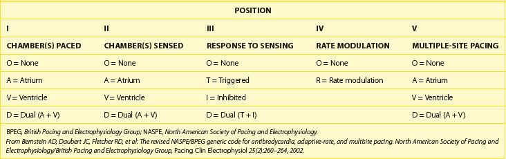
Table 34-2 Abbreviations and Description of Cardiac Events and Timing Cycles in Single-Chamber, Dual-Chamber, and Biventricular Pacemakers/Devices
| CARDIAC EVENTS/TIMING CYCLES (ABBREVIATION) | DESCRIPTION |
|---|---|
| SINGLE-CHAMBER (ATRIAL OR VENTRICULAR) PACEMAKER | |
| Atrial sensed event (P/AS) | Sensed a native Atrial depolarization (P wave) |
| Atrial paced event (A/AP) | Delivered Atrial Pacing output |
| Ventricular sensed event (R/VS) | Sensed a native Ventricular depolarization (QRS complex) |
| Ventricular paced event (V/VP) | Delivered Ventricular Pacing output |
| Atrial blanking period (AB) | Atrial sensing amplifier is “blind” and will not detect or respond to atrial sensed event |
| Ventricular blanking period (VB) | Ventricular sensing amplifier is “blind” and will not detect or respond to any ventricular sensed event |
| Atrial refractory period (ARP) | An atrial sensed event will be noted but ignored, without affecting pacemaker timing cycle |
| Ventricular refractory period (VRP) | A ventricular sensed event will be noted but ignored, without affecting pacemaker timing cycle |
| Lower rate limit (LRL) | Minimum pacing rate |
| Upper rate limit (URL) | Maximum pacing rate |
| Maximum sensor rate (MSR) | Maximum pacing rate by rate-responsive sensor |
| DUAL-CHAMBER (ATRIAL AND VENTRICULAR) PACEMAKER | |
| Atrioventricular sequential pacing (AV) | Atrial paced event followed by paced ventricular event |
| P-synchronous V-pacing (PV) | Atrial sensed event followed by paced ventricular event |
| VA Interval (VAI) | Interval from ventricular sensed or paced event to atrial paced event |
| AR (AP-AS) | Atrial paced event followed by ventricular sensed event |
| AV interval or delay (AVI) | Programmed atrioventricular pacing interval |
| Paced AV interval (Paced AVI) | AV interval/delay from atrial paced event (A) to ventricular paced event (V) |
| Sensed AV interval (Sensed AVI) | AV interval/delay from atrial sensed event (P) to ventricular paced event (V) |
| Maximum or upper tracking rate (MTR) | Maximum ventricular pacing rate allowed in response to high sensed atrial rates |
| Postatrial ventricular blanking period (PAVB) | Period when ventricular sensing is “OFF” after an atrial paced event |
| Post-ventricular atrial blanking period (PVAB) | Period when atrial sensing is “OFF” after a ventricular paced or sensed event |
| Post-ventricular atrial refractory period (PVARP) | Period after a ventricular event when the device can sense but not track an atrial event |
| Total atrial refractory period (TARP) | Sum of AVI and PVARP |
| Rate-responsive AV delay (RRAVD) | AV delay that adjusts by shortening as the rate increases. |
| CARDIAC RESYNCHRONIZATION THE RAPY/PACEMAKERS | |
| Biventricular pacing interval or LV offset (V–V) | Timing gap between RV and LV pacing |
| RV refractory period (RVRP) | An RV sensed event maybe noted but ignored, without affecting RV pacing timing cycle |
| LV refractory period (LVRP) | An LV sensed event maybe noted but ignored, without affecting LV pacing timing cycle |
| LV protection period (LVPP) | Period after a ventricular paced or sensed event that prevents inappropriate pacing during vulnerable period |
Pacing Nomenclature
A five-letter pacing mode nomenclature has been adopted (see Table 34-1).1 The first letter refers to the chamber being paced (Omitted or absent, Atrium, Ventricle, and Dual for atrium and ventricle), the second letter refers to the chamber being sensed (Omitted or absent, Atrium, Ventricle, and Dual for atrium and ventricle), and the third letter refers to the response of the pacemaker to a sensed event (Omitted or absent, Inhibit, Trigger or tracking, and Dual for inhibit and trigger). The fourth letter refers to the rate modulation or rate adaptive response to activity (Rate adaptive, and Omitted or absent rate response), and the fifth letter refers to multiple-site pacing (Omitted or absent, Atrium, Ventricle, and Dual for atrium and ventricle).
Pacing Modes
Available pacing modes depend on the location and number of leads implanted. Indications, advantages, and disadvantages of different pacing modes are reviewed in Table 34-3.
Table 34-3 Indications, Advantages, and Disadvantages of Commonly Used Pacing Modes
| PACING MODE | INDICATION/ADVANTAGES | DISADVANTAGES |
|---|---|---|
| Asynchronous (AOO, VOO, DOO) | Pacemaker-dependent patients exposed to noise (e.g., electrocautery during surgery) Avoids oversensing and asystole |
Pacing regardless of intrinsic events Potential risk for arrhythmia induction |
| Single-chamber pacing (AAI, VVI) | AAI: sick sinus syndrome with intact AV node; preserves AV synchrony VVI: atrial fibrillation with slow VR and single-lead ICDs AAI/VVI require a single lead and increase battery longevity |
AAI lacks ventricular pacing in the event of intermittent AV block VVI is associated with AV dyssynchrony (manifest as pacemaker syndrome) VVI has a higher incidence of atrial arrhythmias10 |
| DDD, DDDRV (CRT) |
Preserves AV synchrony (less pacemaker syndrome) Low incidence of atrial arrhythmias and improved hemodynamics |
Requires at least a two-chamber lead system and has less battery longevity |
| DDI | Functions as two different pacemakers (AAI and VVI) Used as mode switch to avoid tracking atrial tachyarrhythmias |
Same as DDD: possible AV dyssynchrony and pacemaker syndrome (does not track atrial sensed events)2,9 |
| VDD | Appropriate sinus node function with AV node disease (e.g., MDT RV lead model 5038); dual chamber with high atrial pacing threshold to minimize battery depletion | Lack of atrial pacing Potential AV dyssynchrony at lower rate limit |
| DVI | Severe sinus bradycardia/standstill and atrial lead malfunction (oversensing) | Asynchronous atrial pacing Potential AV dyssynchrony |
AV, Atrioventricular; VR, ventricular regurgitation; ICDs, implantable-cardioverter-defibrillators; MDT, Medtronic, Inc.; RV, right ventricular.
Single-Chamber or Dual-Chamber Asynchronous Pacing
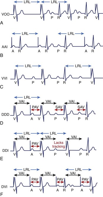
Asynchronous pacing refers to continuous atrial pacing, ventricular pacing, or both at a specific rate, regardless of the presence or absence of an intrinsic atrial event, ventricular event, or both (Figure 34-1, A). Such pacing mode is symbolized as AOO, VOO, or DOO. These pacing modes are used in limited circumstances, such as when pacemaker-dependent patients (without ventricular sensed events) are exposed to noise or artifact (e.g., electrocautery), which could result in asystole due to oversensing and pacing inhibition if the pacemaker has been programmed in a non-asynchronous pacing mode. Nevertheless, asynchronous pacing is often seen when the device is at the end of its life or when a magnet is placed over the pulse generator.
Single-Chamber (Atrial or Ventricular) Inhibited Pacing
Pacemakers with an atrial lead can be programmed to an atrial-inhibited mode referred to as AAI, whereas devices with a ventricular lead can be programmed to a ventricular-inhibited mode (VVI). The AAI pacing mode refers to atrial paced, atrial sensed, and inhibition of pacing output in response to an atrial sensed event (P wave), whereas the VVI pacing mode refers to ventricular paced, ventricular sensed, and inhibition of pacing output in response to a ventricular sensed event (R wave). Therefore the single chamber (atrium or ventricle) will only be paced if no sensed event (P wave or R wave) is detected faster than the programmed lower rate limit (LRL). In contrast, the single chamber (atrium or ventricle) will not be paced if a sensed event is detected (inhibited pacing) at a rate faster than the LRL (Figure 34-1, B and C).
Dual-Chamber (Atrioventricular) Sensing and Sequential, P-Synchronous Pacing with Inhibition (DDD)
The DDD pacing mode requires at least an atrial lead and a ventricular lead. The DDD mode refers to atrial and ventricular pacing as well as atrial and ventricular sensing with dual function (inhibit and trigger pacing) in response to an intrinsic atrial sensed event or a ventricular sensed event. In the DDD mode, the pacemaker will pace both the atrium and the ventricle (atrioventricular [AV] sequential pacing), with programmed AV delay if the intrinsic atrial and ventricular rates are below the LRL. If the atrial rate is slower than LRL, the device will pace the atrium while inhibiting ventricular pacing if an intrinsic ventricular event is sensed within a predetermined AV delay. If an atrial sensed event is faster than the LRL without an intrinsic ventricular event, the pacemaker inhibits atrial pacing but triggers ventricular pacing (P-synchronous pacing) after a predetermined AV delay (Figure 34-1, D). Finally, pacing will be completely inhibited if the intrinsic atrial and ventricular rates are above the LRL. This pacing mode is the most commonly used in dual-chamber devices (DDD or DDDR) and biventricular pacemakers (DDDOV or DDDRV).
Dual-Chamber (Atrioventricular) Sensing and Sequential, Non–P-Synchronous Pacing with Inhibition (DDI)
The DDI pacing mode refers to pacing both the atrium and the ventricle, sensing both the atrium and the ventricle and inhibiting pacing in response to an intrinsic atrial sensed event or a ventricular sensed event. In contrast to DDD, the DDI mode lacks the trigger or P-synchronous pacing in response to an atrial sensed event. Thus the pacemaker will not trigger ventricular pacing after an atrial sensed event, but atrioventricular sequential pacing will occur only after atrial pacing if no intrinsic ventricular event is present (Figure 34-1, E). The overall advantage is that it can function as two different atrial and ventricular pacemakers (AAI with a backup VVI). For example, in a patient with a high-degree AV block, a sinus rate of 80 beats/min, and a programmed LRL of 60 beats/min, the pacemaker will inhibit atrial pacing, but it will pace the ventricle at LRL with the development of AV dyssynchrony due to lack of the trigger or tracking feature. However, when the atrial rate drops below 60 beats/min, the pacemaker will pace both chambers at the LRL with preservation of AV synchrony.
Overall, the most commonly used pacing modes are VVI, DDD, and DDI without rate response or VVIR, DDDR, and DDIR with rate response. VDD and DVI are less commonly used pacing modes. The VDD mode refers to ventricular pacing only and atrial and ventricular sensing with inhibition and tracking function in response to a sensed event. This pacing mode is indicated in patients with normal sinus node function with AV nodal disease, as atrial pacing is not required. This dual-chamber pacing mode may be used with single-pass leads that incorporate both atrial and ventricular electrodes within a single lead body or in subjects with normal sinus node function and appropriate atrial sensing but a high atrial pacing threshold. DVI refers to atrial and ventricular pacing, ventricular sensing only, and inhibition to a ventricular sensed event. This mode lacks atrial sensing, and thus it will pace the atrium asynchronously at the LRL. This mode was used in first-generation pacemakers and thus is more of historical significance (Figure 34-1, F). However, DVI can still be used in patients with significant sinus bradycardia or atrial standstill and atrial lead malfunction (oversensing), in which atrial pacing is mandated (asynchronous pacing). Other pacing modes have a more historical use, such as VAT (ventricular pacing only, atrial sensing only, and tracking response), which could be used on pacemaker-dependent patients to avoid inhibition of ventricular pacing due to ventricular lead oversensing.2–4
Timing Cycles
Recognition of normal pacemaker function versus abnormal pacemaker function on the electrocardiogram (ECG) requires a clear understanding of pacemaker timing cycles. Overall, timing cycles are based on cardiac events such as atrial sensed events and ventricular sensed events (referred to as “P” and “R,” respectively), and atrial paced events or ventricular paced events (referred to as “A” and “V”, respectively). Appropriate sensing of cardiac events allows appropriate function and adaptation of the pacing mode, such as mode switching or noise reversion response (described below). Abbreviations and descriptions of pertinent cardiac events and pacemaker timing cycles are provided in Table 34-2.
Asynchronous pacing modes (AOO, VOO, and DOO) have the simplest timing cycle (they lack blanking and refractory periods) since there is neither sensing nor mode of response (see Figure 34-1, A). Thus, AOO or VOO have a fixed pacing interval, regardless of cardiac events, which depends on the programmable LRL. In addition, DOO has a programmable AV interval (AVI) as well as a ventriculoatrial (VA) interval that depend on the LRL. In contrast, non-asynchronous pacing modes have more timing cycles, including blanking and refractory periods.
Blanking and Refractory Periods
These are basic timing periods that avoid oversensing of inappropriate signals such as evoked potentials and repolarization. During the blanking period, the sense amplifier is “off” or “blind” and will not detect any event. Physiologically, this resembles the absolute refractory period during the cardiac action potential. The main purpose is to avoid cross-talk and oversensing related to evoked potentials. In contrast, the sensing amplifier is “on” during the refractory period and therefore allows detection of rapid signals or cardiac events. Physiologically, this corresponds to the relative refractory period of the cardiac action potential. Sensed events during this period are included in the counters but are ignored and generally do not trigger or reset timing cycles. The presence or absence of blanking and refractory periods depends on specific features of a manufacturer’s pulse generator as well as on the programmed pacing mode (Figure 34-2). Some blanking and refractory periods are not programmable.
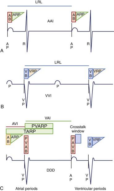
Single-chamber pacing modes have simpler blanking and refractory periods. AAI would start an atrial blanking period (ABP) and an atrial refractory period (ARP) after an atrial sensed or atrial paced event, which would avoid oversensing atrial evoked potentials, atrial repolarization, or ventricular depolarization. Similarly, VVI would start a ventricular blanking period (VBP) and a ventricular refractory period (VRP) after a ventricular sensed or ventricular paced event to avoid oversensing of ventricular evoked potentials and T waves (Figure 34-2, A and B).
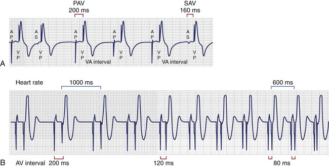
Conversely, dual-chamber pacing modes have more complex timing cycles (Figure 34-2, C). An atrial paced event starts a postatrial ventricular blanking (PAVB) to avoid ventricular oversensing during atrial pacing, whereas a ventricular paced or sensed event starts a PVAB to avoid atrial oversensing during ventricular pacing. If an atrial pacing artifact were to be detected on the ventricular channel, ventricular pacing would be inhibited (cross-talk), resulting in potential asystole in a pacemaker-dependent patient. Thus blanking periods are safety mechanisms that prevent cross-talk. Following the PAVB is a timing period called the ventricular triggering period or cross-talk sensing window, and in the event that a ventricular sensed event occurs during this period, safety pacing will take place. Safety pacing is a feature in which ventricular pacing occurs at an AVI typically shorter than the programmed AVI, often about 100 to 120 ms (programmable interval in some devices), to prevent ventricular asystole. Therefore, cross-talk should be suspected if AV pacing occurs at shorter than programmed AVI (Figure 34-3). Cross-talk can be resolved by extending the PAVB period, decreasing atrial output, or decreasing ventricular sensitivity.2–4
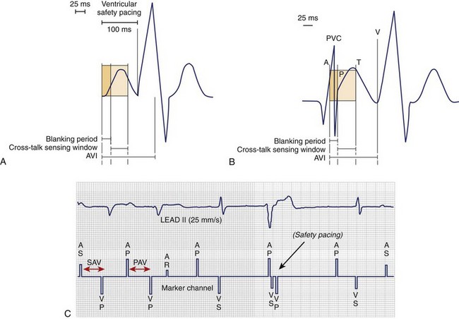
FIGURE 34-3 Blanking period, cross-talk sensing window, and safety pacing. A, Represents ventricular safety pacing at 100 ms when ventricular amplifier senses an event during cross-talk sensing window. B, Premature ventricular contraction (PVC) is not sensed, since it falls within postatrial ventricular blanking followed by ventricular pacing (VP) after completion of the atrioventricular interval (AVI).4 C, PVC occurs simultaneously as the lower rate limit times out and delivers an atrial paced event. Inappropriate safety pacing (100-ms AVI) occurs, since the PVC is sensed during the cross-talk window. PAV, Paced AV interval; SAV, sensed AV interval.
(A and B, From Ellenbogen KA, Wood MA: Cardiac pacing and ICDs, ed 4, Malden, MA, 2005, Blackwell.)
Furthermore, an atrial sensed event or an atrial paced event starts ARP and AVI. After the AVI is timed out, the pacemaker will deliver a ventricular paced event if no intrinsic ventricular sensed event is noted. A ventricular sensed event or a ventricular paced event starts VRP and postventricular atrial refractory period (PVARP). The VRP avoids sensing the evoked response and T wave, whereas PVARP avoids inappropriate atrial oversensing of ventricular repolarization, tracking of retrograde P wave, or both. The total atrial refractory period (TARP) is the sum of AVI and PVARP (see Figure 34-2, C). During TARP, any atrial sensed event noted does not affect the timing cycle. As a consequence, TARP limits the maximum tracking rate (MTR) in the DDD (P-synchronous) mode, as well as the upper rate limit (URL) or maximum sensor rate (MSR) in a non–P-synchronous mode and a rate-adaptive response, respectively. Thus, lengthening TARP will subsequently decrease the MTR, URL, or MSR. Atrial sensed events falling in TARP may not be tracked in a DDD pacing mode, but they will be detected and counted to detect higher atrial rates and trigger the mode-switch algorithm. PVARP should be extended to include a retrograde P wave only if VA conduction is present. Inappropriately short PVARPs can lead to a sensed retrograde P wave after a premature ventricular contraction (PVC), which will start an AVI followed by a ventricular paced event. This can set up a cycle of sensed retrograde P waves, causing an endless-loop pacemaker tachycardia, also called pacemaker-mediated tachycardia (PMT). PMT is a form of AV dyssynchrony or VA synchrony. PMT should be suspected when P-synchronous ventricular pacing is noted at the MTR with a sudden onset that occurs after PVC (Figure 34-4, A). Commonly, PMT may also be seen during atrial threshold testing, such as auto threshold, which causes a ventricular paced event after loss of atrial capture. This, in turn, leads to retrograde VA conduction with initiation of PMT if the atrial sensed event occurs beyond PVARP. More complex algorithms cause suspicion of PMT when the VP-P interval is stable, and they will confirm PMT if the measurement of the VP-P interval remains stable after alteration of the next P-V interval (Figure 34-4, B).5 However, if the VP-P interval lengthens or shortens after changing the P-V interval, the device excludes PMT and continues with P-synchronous tracking of the atrial rhythm. All device manufacturers have algorithms to interrupt suspected PMT. The most common algorithms include a withholding of a single ventricular pacing output, an extension of PVARP for a single cycle, and interruption of P-synchronous pacing after the AVI is met followed by sequential AV pacing (see Figure 34-4, B).5–7
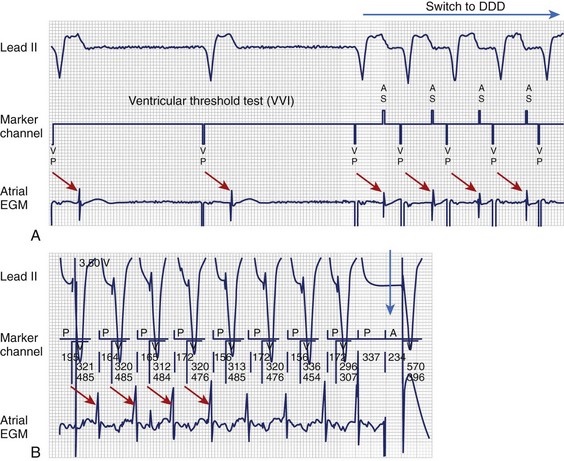
FIGURE 34-4 Pacemaker-mediated tachycardia (PMT). A, PMT initiated once the V-V interval (VVI) pacing mode switches to DDD during the ventricular pacing threshold. Red arrows illustrate VA timing from VP to atrial electrogram (EGM), which is only sensed and tracked after the device changes to the DDD mode. B, VP-P interval (red arrow) remains stable after changing the PV interval or sensed AV interval (P-synchronous pacing), which confirms retrograde VA conduction and PMT. Sequential atrial and ventricular pacing (blue arrow) is delivered to terminate PMT.4
(From Ellenbogen KA, Wood MA: Cardiac pacing and ICDs, ed 4, Malden, MA, 2005, Blackwell.)
Base-Rate Behavior
Pacemakers from different manufacturers vary in their responses to sensed events. Dual-chamber pacemakers have been historically designed with a ventricular-based timing system. Designation of timing system, for example, atrial-based timing system, ventricular-based timing system, or hybrid-based timing system—gained importance with the innovation of rate-adaptive pacing. As long as the LRL pacing remains stable, no difference is discernible between atrial and ventricular timing systems.2–4
Ventricular-based timing is characterized by a predetermined VA interval (VAI), which starts after a ventricular sensed event and will time out the next atrial paced beat. A ventricular sensed event (e.g., PVC) during the VAI will reset the VAI. The ventricular rate is determined by the sum of VAI and AVI (Figure 34-5, A). A ventricular sensed event during the AVI terminates the AVI and initiates VAI. Therefore, the resulting A-A interval is shorter (slightly faster rate than programmed LRL) based on a P-R interval shorter than the programmed AVI.
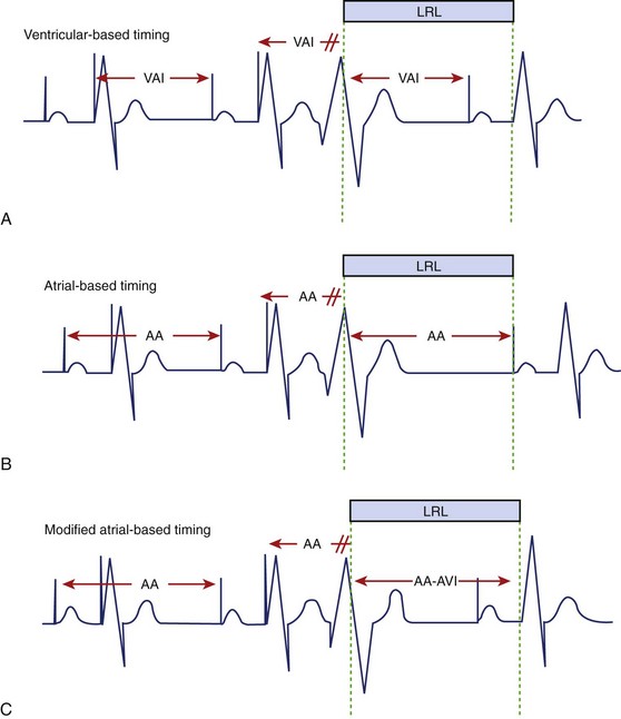
Atrial-based timing is characterized by an A-A interval that will time out the next atrial paced beat and subsequently determine pacing rate. A sensed R wave during AVI (intrinsic AV conduction) inhibits ventricular pacing but does not change basic A-A timing, and the ventricular rate stays at the LRL. A sensed R wave during VAI resets the A-A timing, and thus the ventricular rate maybe slightly slower than the programmed LRL (A-A plus AVI; Figure 34-5, B).
The main difference between atrial-based timing and ventricular-based timing can be demonstrated in patients with underlying 2 : 1 AV block at a lower rate. During 2 : 1 AV block, AV (AP-VP) and AR (AP-VS) events alternate. The ventricular-based timing may increase pacing rate during AR, but the LRL is never violated. Atrial-based timing results in alternating cycles that are either faster or slower than the LRL but never the same as the programmed LRL (Figure 34-6, A).
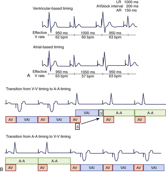
FIGURE 34-6 Atrial, ventricular, and hybrid base-rate behavior. A, Ventricular and atrial-based timing with underlying 2 : 1 atrioventricular (AV) block (AV block interval is longer than atrial rate). Top: AV block interval is slightly longer than atrial rate, hence the rate alternates with the rate at the lower rate limit (LRL; 60 beats/min) and slightly faster than the LRL (63 beats/min) in ventricular-based timing. Bottom: Atrial-based timing violates LRL with an alternating faster (63 beats/min) and slower (57 beats/min) ventricular rate than programmed LRL. B, Hybrid-based timing.6 Top: Timing changes from ventricular based to atrial based after a ventricular sensed event is noted (Δ, difference between P-R interval and A-V interval in the first cycle during which intrinsic conduction occurs). Δ is applied to next V-A interval (VAI) to provide a smooth transition without affecting V-V intervals. Bottom: Timing changes from atrial based to ventricular based when intrinsic AV nodal conduction is no longer present.
(A, From Ellenbogen KA, Wood MA: Cardiac pacing and ICDs, ed 4, Malden, MA, 2005, Blackwell; and Siemens-pacesetter; B, From Insignia I Ultra System Guide, models 1190/1290/1291, St. Paul, MN, 2006, Guidant Corporation.)
Currently, most pacemakers have modified atrial-based timing or hybrid-based timing designated to avoid the potential rate variations or limitations that could occur with a pure atrial-based timing system or a ventricular-based timing system. These hybrid-based timing algorithms vary among different manufacturers (Figures 34-5, C, and 34-6, B).5–7 For example, atrial-based timing may change to ventricular-based timing after PVC (ventricular sensed event), whereas a sensed R wave during the AVI (intrinsic AV conduction) is ignored and does not reset the A-A interval (see Figure 34-5, C).
Atrioventricular Interval or Delay
All dual-chamber contemporary devices have a differential AVI, or AV delay, that depends on whether the atrium is paced or sensed (Figure 34-7, A). This is based on the native atrial depolarization being commonly sensed 20 to 60 ms after the onset of the P wave.8 In contrast, the P wave starts immediately after an atrial paced event. For example, if AVI is programmed at 160 ms for an atrial sensed event as well as an atrial paced event, the true ECG-based P-R interval following an atrial sensed event would be 180 to 220 ms compared with 160 ms in the atrial paced event. Therefore, the AVI started by an atrial sensed event (also referred to as the P-V interval) should be shorter than the one that follows an atrial paced event. The main purpose of differential AVI is to provide a similar functional P-R interval and adequate ventricular filling, regardless of an atrial sensed event or an atrial paced event. Most pacemakers allow programming of different paced AVIs and sensed AVIs, with differences up to 100 ms.5–7
Dynamic or rate-adaptive AV delay is a feature that allows shortening the AVI as the atrial rate increases, either during sinus rhythm or during sensor-driven pacing (Figure 34-7, B). This feature is intended to mimic the normal physiology, in which the P-R interval shortens as the heart rate increases to optimize cardiac output. Subsequently, this allows atrial tracking at faster rates because of a shorter TARP (AVI + PVARP). Different manufacturers have different methods to achieve a dynamic AVI. The most common method is linear shortening of the AVI from a programmed baseline AVI to a programmed minimum AVI. Another method is stepwise shortening of the AVI.5–7
AV hysteresis has significantly changed over the years. This term refers to the alteration of the AVI, depending on AV nodal conduction. Of historical interest, negative hysteresis refers to shortening of the AVI to maintain a paced ventricular rhythm.2 This was available when a high percentage of ventricular pacing was thought to have beneficial effects and remains useful in biventricular pacemakers to ensure a high percentage of ventricular pacing. AV hysteresis, previously known as positive hysteresis, describes alterations in the paced AVI to promote intrinsic AV conduction.2,3 Contemporary algorithms, such as minimal ventricular pacing and search AV, achieve a similar purpose.6,7 AV hysteresis is no longer used because newer algorithms with better defined behavior are now available. These algorithms are described below.
Upper Rate Behavior
Atrial sensed events (such as sinus tachycardia) terminate the VAI and initiate an AVI. P-wave–synchronous pacing occurs with a 1 : 1 AV relationship as long as the atrial rate is between the programmed LRL and MTR. The AVI and the MTR must complete their cycles to deliver ventricular pacing. If the atrial rate is faster than TARP (AVI + PVARP), some P waves are not tracked, and the pacemaker behaves similar to a 2 : 1, 3 : 1 AV block and so on, depending on the atrial rate (Figure 34-8, A). Thus, a long PVARP results in a fixed AV block response at a relatively low tracking rate. This may be an important issue in some patients since abrupt changes in pacing rate with intermittent lack of tracking can result in significant symptoms.2,3,9
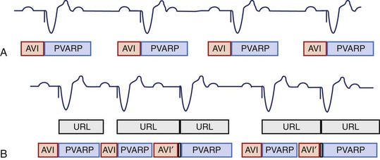
In addition, pacemakers may mimic AV nodal Wenckebach behavior (e.g., “electronic” Wenckebach) when the atrial rate exceeds the MTR. AV nodal Wenckebach behavior is characterized by a progressive P-V interval prolongation until a sensed P wave falls into PVARP and is ignored by the pacemaker, resulting in a pause (see Figure 34-8, B). Wenckebach behavior will occur with atrial rates between the MTR and TARP, which can be calculated as the Wenckebach interval (WI = MTR – TARP).2,4 For example, a programmed MTR of 400 ms and TARP of 350 ms (AVI 125 + PVARP 225) results in a Wenckebach interval of 50 ms, which means that Wenckebach behavior will occur within a 50-ms range (P-P interval 350 to 400 ms). Moreover, 2 : 1, or fixed block, pacemaker behavior occurs when the P-P interval is shorter than 350 ms. Nevertheless, Wenckebach behavior will not occur if the Wenckebach interval is 0 (e.g., MTR 400, TARP [AVI 250 + PVARP 150]), but a 2 : 1 or fixed AV block pacemaker behavior will occur as soon as the P-P interval is faster than the MTR (see Figure 34-8, A).
Special Pacing Features
Rate Smoothing or Atrial/Ventricular Rate Stabilization
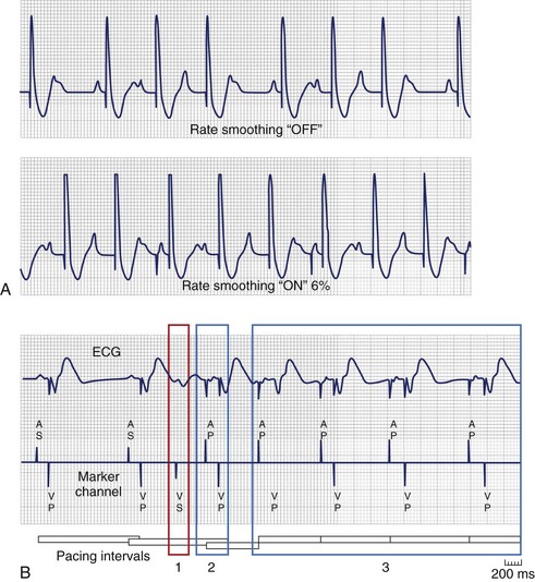
Rate smoothing (RS) or atrial/ventricular rate stabilization (ARS/VRS) is a variation of upper rate behavior. ARS/VRS, or RS, was developed to prevent marked changes in A-A and V-V intervals not only at the URL but also when sinus rhythm (SR) is interrupted by profound bradycardia or asystole. Single-chamber and dual-chamber non–P-synchronous pacing modes operate between the LRL and the URL (the MSR, if rate-adaptive response is enabled), whereas P-synchronous pacing modes operate between the LRL and the MTR. This feature is recommended in patients with large symptomatic variations in ventricular rate, such as sinoatrial disease, atrial flutter/fibrillation, premature atrial and ventricular contractions, and Wenckebach pacemaker behavior (Figure 34-9). Most recently, biventricular devices have added VRS and RS in an attempt to increase the percentage of biventricular pacing during conducted atrial arrhythmias. These algorithms vary among different manufacturers.6,7 For example, RS can be programmed to percentage change (3% to 24% in 3% increments) between V-V cycles. Importantly, this feature is typically unavailable if rate drop response (described below) is enabled.
Hysteresis
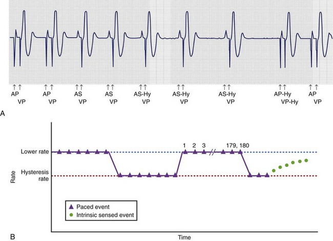
Hysteresis is a feature found in single-chamber and dual-chamber pacemakers. In an attempt to maintain intrinsic atrial and ventricular activation, both single-chamber and dual-chamber pacemakers use this feature to allow intrinsic conduction after a sensed P or R wave has occurred. (Figure 34-10, A).2–6 For example, a pacemaker programmed with an LRL of 60 beats/min and hysteresis offset of 10 beats/min (60 − 10 = 50 beats/min) will pace at 60 beats/min until an intrinsic event (P or R wave) is sensed above the LRL (>60 beats/min). Hysteresis rate of 50 beats/min will allow an extra 200 ms for another sensed P or R wave to occur. In the case of adaptive-rate modes, hysteresis rate is below the sensor-indicated rate instead of the LRL. However, if no intrinsic event (P or R wave) is sensed above the sensor-indicated rate or the LRL, the pacemaker will continue to pace at 60 beats/min. To overcome this limitation and in an attempt to allow the intrinsic native rhythm to appear, scan or search hysteresis was later introduced to periodically decrease the pacing rate to the hysteresis rate after a specific number of cycles (Figure 34-10, B).2,5,6
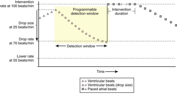
A more contemporary form of hysteresis is referred to by some manufacturers as sudden bradycardia response or rate drop response. This feature was developed and is used primarily to treat vasovagal or neurocardiogenic syncope.5–7 The purpose of this feature is to allow pacing that is faster than the LRL when the intrinsic rate decreases below a specified programmed rate. Figure 34-11 demonstrates rate drop response (Medtronic, Inc.) pacing at an intervention rate of 100 beats/min for a programmable duration only if the heart rate drops more than the programmed heart rate drop of 25 beats/min (from 95 beats/min to <70 beats/min) within a programmed detection window. As another example, a hysteresis of −30 and an LRL of 90 will not pace until the heart rate drops below the programmed hysteresis rate (60 beats/min). Once the heart rate drops below 60 beats/min, the device will pace at an LRL of 90 beats/min for a specific predetermined or programmed number of timing cycles. After the programmed number of paced beats is met, a prolonged escape interval is permitted to allow intrinsic conduction above the hysteresis rate.
Algorithms to Promote Intrinsic Atrioventricular Conduction
Different manufacturers have developed algorithms to promote intrinsic AV nodal conduction and minimize ventricular pacing. This feature obtained special attention after the deleterious effects of frequent ventricular pacing, such as exacerbation of heart failure and increased risk of atrial fibrillation, were recognized.9,10
AV Search Hysteresis
This was the first algorithm to promote AV conduction.2–4 Specific details of AV hysteresis vary among different manufacturers.5,6 This algorithm may also be referred to as AV hysteresis or ventricular intrinsic preference (VIP). Essentially, these algorithms allow programming a baseline AVI and delta (Δ) AVI, or AVI extension. Thus, AVI + Δ promotes intrinsic AV conduction (Figure 34-12, A). In the event that AV sequential pacing is present, the device will periodically extend the AV delay by the programmed Δ for up to a programmed number of consecutive cardiac cycles in an attempt to allow intrinsic conduction. If no intrinsic AV conduction is noted at AVI + Δ, AV pacing will revert to the baseline programmed AVI. Another variation of this algorithm is a gradual extension of the AVI up to the programmed extension.
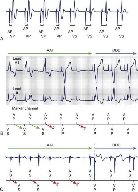
Managed Ventricular Pacing
The MVP algorithm allows two pacing modes, alternating AAI and DDD on demand (Figure 36-12, B).7 After an atrial sensed or atrial paced event, intrinsic conduction is allowed; however, after transient loss of AV conduction, a backup ventricular paced beat is delivered. Persistent loss of AV conduction, defined by this algorithm as 2 of 4 consecutive nonrefractory A-A intervals without an R event, will switch to the DDD pacing mode. The algorithm periodically assesses for return of AV conduction after 1 minute of DDD pacing, and AAI is restored when intrinsic AV conduction returns. The MVP algorithm has been shown to promote intrinsic AV conduction with an 85% reduction of cumulative ventricular pacing compared with DDD/R.11
AAISafeR2 Sorin
AAISafeR2 (Figure 34-12, C) is a more complex and tolerant algorithm to minimize ventricular pacing.2,3,12 First-, second-, and even third-degree AV blocks are allowed up to a preset level before the algorithm switches to the DDD pacing mode. The algorithm will automatically change to DDD at the pre-programmed AV delay if any of the following occur: (1) two consecutive blocked P waves (high-degree AV block), (2) more than three blocked P waves within 12 cycles (second-degree AV block), (3) ventricular pause above a programmed duration between 2 and 4 seconds, and (4) more than six consecutive abnormal PR/AR intervals above a certain programmed value (first-degree AV block, PR >350 ms, and AR >450 ms). This last criterion for first-degree AV block can be disabled. This algorithm will attempt to assess and restore intrinsic AV conduction after 12 consecutive sensed R waves or 100 DDD cycles have occurred. AAI pacing will be disabled until the next time the device is programmed if “persistent” AV conduction abnormality is noted, defined as more than 50% of the time in DDD mode. However, if AV block is detected during exercise (heart rate >100 beats/min), the event will not add to the counter for persistent DDD operation. Finally, while in DDD(R) mode after an episode of persistent AV block, the device will assess for intrinsic AV conduction and attempt to return to AAI(R) every morning when the patient awakens.
Algorithms to Avoid Competition of Native and Paced Atrial Rhythm
Noncompetitive Atrial Pacing
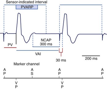
If a refractory atrial sensed event occurs within PVARP, a programmable (300-ms default) noncompetitive atrial pacing (NCAP) interval is initiated.2,3,7 No atrial pacing will occur during the 300-ms NCAP, even if the programmed VAI is completed. VAI will be extended until the 300-ms NCAP expires. If a new atrial sensed event occurs during NCAP, the 300-ms NACP is reset. In case the atrial paced event is delayed by NCAP, the PAV interval will be shortened in an attempt to keep the ventricular rate stable (Figure 34-13).
Atrial Protection Interval
This algorithm shortens the PVARP for each interval where the pseudo-Wenckebach window is less than 125 ms, providing a noncompetitive pacing window of 125 ms.3 By shortening the PVARP, the atrial sensed event will reset the VAI or the A-A interval depending on the base-rate behavior (ventricular-, atrial-, or hybrid-based timing).
Sinus Preference
This algorithm is comparable with rate hysteresis and intends to maintain atrial sensing.2,3,7 This allows a gradual decrease of the sensor-indicated pacing rate to a lower rate in search of SR. SR is allowed to predominate if it is detected within the programmable lower rate. However, if the sinus rate is not detected at the programmed lower rate for eight paced beats, the paced rate will gradually increase to the sensor-indicated rate. This operation restarts once a programmable search interval times out. Sinus preference cannot be enabled with the MVP algorithm, and it is temporarily disabled if the pacemaker switches to a nonatrial tracking mode.
Arrhythmia-Search Algorithms
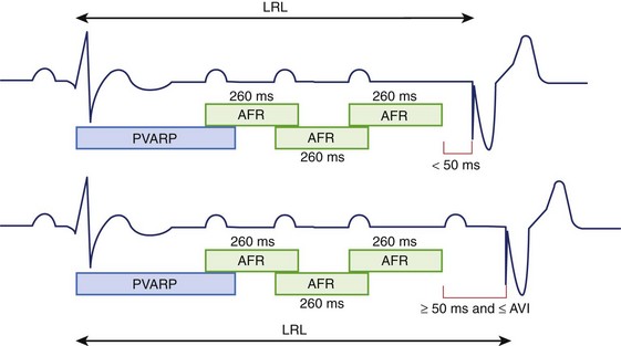
Atrial Flutter Response
If an atrial sensed event occurs within PVARP, an atrial response window starts a 260-ms interval, which will restart if another atrial event is sensed.2,6 In the absence of an atrial sensed event, an atrial paced event will occur only in the presence of at least 50 ms before the LRL interval is met. A ventricular paced event will occur, with or without atrial pacing, if no sensed event is noted at the LRL interval (Figure 34-14).
Mode Switch
Mode switch refers to the ability to change automatically from one pacing mode to another in response to a rapid atrial rate. Therefore, this feature is used in patients with paroxysmal supraventricular tachycardia to eliminate tracking of atrial tachyarrhythmias. A counter should complete a specified number of short P-P intervals to mode switch to a nonatrial tracking mode, such as DDI(R) and VVI(R). Similarly, the mode switch reverts to the prior atrial tracking mode when a specified number of long P-P intervals are met. It is essential to sense atrial events that occur during part of the AVI and PVARP to avoid undersensing of atrial tachyarrhythmias. In contrast, PVAB is important to avoid atrial oversensing because of ventricular pacing, which could potentially cause an inappropriate mode switch. Shorter PVAB allows detection of higher atrial rates, whereas longer PVAB is more likely to undersense atrial tachyarrhythmias. Automatic mode switching is described in more detail in Chapter 33.
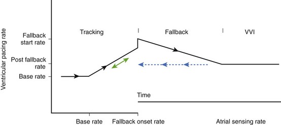
Fallback
This feature is intended to avoid abrupt symptomatic pauses related to Wenckebach behavior and fixed block once mode switch criteria have been met.2,3 Once the pacing mode has switched, the device will gradually decrease the ventricular paced rate to the sensor rate or to the fallback LRL (Figure 34-15). The fallback time determines how quickly the rate will decrease to the sensor-determined rate or to the fallback LRL. When the atrial rate slows below the MTR or the fallback rate, AV synchrony is restored. This feature may vary among different manufacturers.
Response to Magnet Application
Responses to magnet application may vary depending on the programming of the device and its manufacturer.2,3,5–7 In general, sense amplifiers will be disabled during magnet application, resulting in asynchronous pacing in single-chamber (VOO, AOO) or dual-chamber pacemakers (DOO). However, the individual specifics for magnet application should be understood for each pacemaker. Some pacemakers have a programmable feature to turn “off” magnet response, whereas others may “enable” storage of diagnostic electrograms with magnet application. In addition, some pacemakers will not display asynchronous pacing when in a “reset mode.” Moreover, pacemakers from some manufacturers will continue to pace asynchronously for a number of beats after magnet removal, while others may have different pacing rates that may also vary depending on battery status.
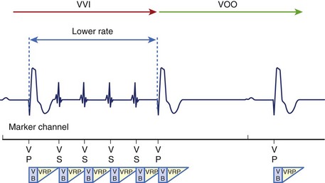
Noise Reversion Response
Noise reversion response is a feature designed to identify inappropriately sensed artifacts, such as electromagnetic interference (EMI). Many sources of EMI exist in today’s world. Noise response algorithms also vary from manufacturer to manufacturer.2,3,6,7 The basic principle of noise reversion is to tag continuous signals as “noise” in ARP or VRP with nonphysiological rates exceeding 400 to 600 cycles/min (7 to 10 Hz). Noise reversion response will switch the pacing mode to an asynchronous mode at the LRL in non–rate-adaptive pacing modes or to the sensor-indicated rate in rate-adapting pacing modes in most devices (Figure 34-16).
Special Biventricular Cycle Timing and Pacing Features
Left Ventricular Refractory and Protection Periods
Biventricular pacing should be maximized to provide optimal symptomatic and survival benefit.9,13 Even though biventricular devices base their timing cycle on RV sensed and paced events, LV refractory and protection periods are important to maximize cardiac resynchronization therapy (CRT) without increasing the risk of inducing ventricular arrhythmias.3,13,14 These periods are programmable by some manufacturers. Similar to the right VRP, the LV refractory period (LVRP) is initiated after a left ventricular VP or VS event. LVRP will ignore LV sensed events without resetting or affecting the LV pacing timing cycle. The purpose of LVRP is to avoid inappropriate loss of CRT due to LV oversensing. For example, T-wave oversensing could inhibit LV pacing, which can be avoided by increasing LVRP to include the T wave. However, a long programmed LVRP will shorten the LV sensing window.
The LV protection period (LVPP) prevents inappropriate LV pacing during the LV vulnerable period, such as with LV PVC, which could induce ventricular tachyarrhythmias. However, a long programmed LVPP limits the MTR or MSR and can potentially inhibit CRT at higher pacing rates. This period is available only if LV sensing and pacing are enabled. Importantly, a ventricular sensed event in LVPP will inhibit only LV pacing without affecting RV pacing for bradycardia support.14
V–V Timing
A programmable RV-LV delay (better known as V-V delay, or LV offset) has been recently added to most biventricular devices to allow different timing between RV and LV pacing. The first generation of biventricular devices had nonprogrammable simultaneous RV and LV pacing. This was developed in an attempt to improve the clinical response by improving resynchronization between RV and LV activation. Programmable V-V delay varies among different manufacturers.14,15 Some allow LV pacing to occur from 0 to 100 ms before RV pacing, whereas others allow LV pacing even after RV pacing. However, conflicting results have been reported from different studies with regard to the optimal V-V delay as well as the utility of ECG-based optimization of V-V delay.2,9
Biventricular Trigger or Ventricular Sense Response
Biventricular trigger (BiVT), also known as ventricular sense response, was developed in an attempt to promote biventricular resynchronization in the event of frequent premature ventricular contractions and atrial tachyarrhythmias after mode switch has occurred to a nontracking mode. BiVT will provide biventricular pacing between the LRL and the URL or the MTR.14,15 Some manufacturers have a programmable BiVT maximum pacing rate, which will limit this feature below the MTR in dual-chamber devices. BiVT, together with VRS or RS (described above), is intended to further increase resynchronization therapy.
Key References
Bernstein AD, Daubert JC, Fletcher RD, et al. The revised NASPE/BPEG generic code for antibradycardia, adaptive-rate, and multisite pacing. North American Society of Pacing and Electrophysiology/British Pacing and Electrophysiology Group. Pacing Clin Electrophysiol. 2002;25(2):260-264.
Bristow MR, Saxon LA, Boehmer J, et al. Cardiac-resynchronization therapy with or without an implantable defibrillator in advanced chronic heart failure. N Engl J Med. 2004;350(21):2140-2150.
2008 Cognis 100-D System Guide. In: Cardiac resynchronization therapy high energy defibrillator. Models N118, N119. St Paul, MN: Boston Scientific; 2008.
2006 Cylos pacemaker feature handbook. In: Premium dual-sensor pacemaker family. Lake Oswego, OR: Biotronik Inc; 2006.
Ellenbogen KA. Clinical cardiac pacing, defibrillation, and resynchronization therapy, ed 3. Philadelphia: Saunders; 2007.
Ellenbogen KA, Wood MA. Cardiac pacing and ICDs, ed 4. Malden, MA: Blackwell Publishing; 2005.
Fröhlig G, Gras D, Victor J, et al. Use of a new cardiac pacing mode designed to eliminate unnecessary ventricular pacing. Europace. 2006;8(2):96-101.
Hayes DL, Asirvatham SJ, Friedman PA. Pacemaker and cardiac resynchronization timing cycles and electrocardiography. In: Hayes DL, editor. Cardiac pacing, defibrillation and resynchronization. A clinical approach. Chichester, West Sussex, UK, Hoboken, NJ: Wiley-Blackwell Publishing, 2008.
Insignia I. Ultra System Guide. In: Models 1190/1290/1291. St Paul, MN: Guidant Corporation; 2006.
Janosik DL, Pearson AC, Buckingham TA, et al. The hemodynamic benefit of differential atrioventricular delay intervals for sensed and paced atrial events during physiologic pacing. J Am Coll Cardiol. 1989;14(2):499-507.
Kaszala K, Huizar JF, Ellenbogen KA. Contemporary pacemakers: What the primary care physician needs to know. Mayo Clin Proc. 2008;83(10):1170-1186.
2006 Medtronic Adapta, Versa, Sensia. In: Pacemaker reference guide. Minneapolis, MN: Medtronic, Inc; 2006.
2008 Medtronic Concerto. In: Resynchronization therapy and defibrillator reference guide. Minneapolis, MN: Medtronic, Inc; 2008.
Sweeney MO, Ellenbogen KA, Casavant D, et al. Multicenter, prospective, randomized safety and efficacy study of a new atrial-based managed ventricular pacing mode (MVP) in dual chamber ICDs. J Cardiovasc Electrophysiol. 2005;16(8):811-817.
Sweeney MO, Hellkamp AS, Ellenbogen KA, et al. Adverse effect of ventricular pacing on heart failure and atrial fibrillation among patients with normal baseline QRS duration in a clinical trial of pacemaker therapy for sinus node dysfunction. Circulation. 2003;107(23):2932-2937.
1 Bernstein AD, Daubert JC, Fletcher RD, et al. The revised NASPE/BPEG generic code for antibradycardia, adaptive-rate, and multisite pacing. North American Society of Pacing and Electrophysiology/British Pacing and Electrophysiology Group. Pacing Clin Electrophysiol. 2002;25(2):260-264.
2 Ellenbogen KA. Clinical cardiac pacing, defibrillation, and resynchronization therapy, ed 3. Philadelphia: Saunders; 2007.
3 Hayes DL, Asirvatham SJ, Friedman PA. Pacemaker and cardiac resynchronization timing cycles and electrocardiography. In: Hayes DL, editor. Cardiac pacing, defibrillation and resynchronization. A clinical approach. Chichester, West Sussex, UK, Hoboken, NJ: Wiley-Blackwell Publishing, 2008.
4 Ellenbogen KA, Wood MA. Cardiac pacing and ICDs, ed 4. Malden, MA: Blackwell Publishing; 2005.
5 Cylos pacemaker feature handbook. In: Premium dual-sensor pacemaker family. Lake Oswego, OR: Biotronik Inc; 2006.
6 Insignia I. Ultra System Guide. In: Models 1190/1290/1291. St Paul, MN: Guidant Corporation; 2006.
7 Medtronic Adapta, Versa, Sensia. In: Pacemaker reference guide. Minneapolis, MN: Medtronic, Inc; 2006.
8 Janosik DL, Pearson AC, Buckingham TA, et al. The hemodynamic benefit of differential atrioventricular delay intervals for sensed and paced atrial events during physiologic pacing. J Am Coll Cardiol. 1989;14(2):499-507.
9 Kaszala K, Huizar JF, Ellenbogen KA. Contemporary pacemakers: What the primary care physician needs to know. Mayo Clin Proc. 2008;83(10):1170-1186.
10 Sweeney MO, Hellkamp AS, Ellenbogen KA, et al. Adverse effect of ventricular pacing on heart failure and atrial fibrillation among patients with normal baseline QRS duration in a clinical trial of pacemaker therapy for sinus node dysfunction. Circulation. 2003;107(23):2932-2937.
11 Sweeney MO, Ellenbogen KA, Casavant D, et al. Multicenter, prospective, randomized safety and efficacy study of a new atrial-based managed ventricular pacing mode (MVP) in dual chamber ICDs. J Cardiovasc Electrophysiol. 2005;16(8):811-817.
12 Fröhlig G, Gras D, Victor J, et al. Use of a new cardiac pacing mode designed to eliminate unnecessary ventricular pacing. Europace. 2006;8(2):96-101.
13 Bristow MR, Saxon LA, Boehmer J, et al. Cardiac-resynchronization therapy with or without an implantable defibrillator in advanced chronic heart failure. N Engl J Med. 2004;350(21):2140-2150.
14 Cognis 100-D System Guide. In: Cardiac resynchronization therapy high energy defibrillator. Models N118, N119. St Paul, MN: Boston Scientific; 2008.
15 Medtronic Concerto. In: Resynchronization therapy and defibrillator reference guide. Minneapolis, MN: Medtronic, Inc; 2008.