Chapter 159 Biomechanics of Motion Preservation Techniques
For many years, cervical and lumbar arthrodesis has been the gold standard of treatment for a wide range of degenerative, traumatic, deformational, and oncologic spinal disorders. Although spinal arthrodesis has been used with great success, from a biomechanical perspective, it significantly alters the regional and global balance of physical forces and moments. As a consequence, several studies have demonstrated accelerated degenerative changes at levels directly adjacent to rigid spinal fusions.1–3 This is commonly termed adjacent-segment degeneration (ASD). Specifically, it is thought that the stiffness imposed by a rigid fusion on an adjacent vertebral functional spinal unit (FSU) alters stress transfer between the vertebral segments and predisposes adjacent segments to accelerated degeneration. As a result of this, motion-sparing technologies have emerged in an attempt to preserve the native motion of the spinal unit, predominantly at the disc interspace. Theoretically, if a motion-sparing implant closely simulates the biomechanical properties of the intact FSU, the incidence of ASD would be expected to decrease.
The earliest and most traditional form of motion preservation surgery came in the form of laminectomy, laminoplasty, and laminoforaminotomy. These techniques were designed to treat underlying spinal pathology while preserving as much of the natural motion of the spine as possible. They involve a small amount of bone removal and preservation of the facets and many of the supporting ligaments, and do not violate the disc. In particular, the laminoforaminotomy has been shown to induce the least disruption in normal spinal mobility and stiffness compared with traditional laminectomy.4 There is, however, a limited range of pathologic processes for which these techniques are indicated (and effective).
Biomechanics of the Functional Spinal Unit
Physical Principles
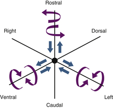
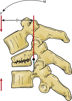
A vector is a force oriented in a fixed direction in three-dimensional space. All forces acting on the spine can be described in terms of their component vectors. A vector may act on a lever (moment arm), resulting in a bending moment. A bending moment applied to a point in space causes rotation (or a tendency to rotate) about an axis, called the instantaneous axis of rotation (IAR). Movement about the IAR can be described in terms of the cartesian coordinate system (Fig. 159-1). The IAR is the point or location in three-dimensional space about which each vertebral segment rotates at any given instant. The location of the IAR is not fixed, but rather is variable (mobile) depending on the intrinsic curvature of the spine and any other intrinsic or extrinsic forces that may act on the spine5 (Fig. 159-2).
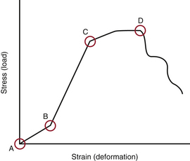
When several forces act on a solid with a resultant net force of zero, the solid is deformed. A stress-strain curve describes this relationship (Fig. 159-3). Stress is defined as the force applied to an object (load). Strain is defined as the response of the object to the force (deformation). The neutral zone or zone of nonengagement describes the reaction of a solid to stress before deformation of that solid is realized. When the neutral zone is exceeded and stress continues, the solid enters into the elastic zone. The elastic zone describes applied stress (usually of lower magnitude) that results in strain that is completely recoverable after removal of stress. As the applied force increases, the elastic limit is reached and the plastic zone is entered. At this point, increased stress results in permanent deformation of the solid up to the point of failure, when the solid yields.
Intervertebral Disc
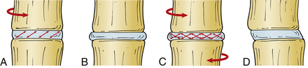
The intervertebral discs contain a peripherally located anulus fibrosus and a centrally located nucleus pulposus. The cartilaginous end plates form the rostral and caudal limits of the intervertebral discs. The fibers of the anulus are arranged radially in opposite directions about the vertebral body interspace between the end plates, whereas the nucleus pulposus is contained within the anulus. The anulus contains two types of laminated (mostly collagenous) fibers: radial fibers that attach to the cartilaginous end plates (called inner fibers) and to the cortical bone on the edge of the vertebral bodies (called Sharpey fibers). These fibers are oriented roughly 30 degrees with respect to the end plate and opposite to each other, which gives the disc the ability to resist rotational forces (Fig. 159-4). The nucleus pulposus is a gel-like remnant of the embryonal notochord. It is composed of reticular bands surrounded by a thick mucoid ground substance.
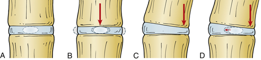
The intervertebral disc can resist significant axial forces; however, this ability decreases with age. A pure (i.e., central) axial load causes symmetrical deformation of the disc because the intradiscal pressures are distributed symmetrically. In the presence of flexion, extension, or lateral bending (i.e., eccentric) forces, the intradiscal pressures are distributed asymmetrically and the normal disc will deform in a relatively predictable manner. The anulus bulges on the side of the deformation and stretches on the side opposite to the load, whereas the nucleus pulposus tends to move away from the area of applied force (in the opposite direction from the anular bulge)5 (Fig. 159-5).
Studies of the nucleus pulposus in vitro demonstrate its importance in intervertebral disc biomechanics. Mechanical denucleation of intervertebral discs in cadaver lumbar spine segments results in increased range of motion and neutral zone compared with intact discs. Removal of the nucleus also results in decreased disc height and segment stiffness. Interestingly, the nucleus is most effective at lower loads, before the anulus has a chance to be engaged in a more effective tensile load-bearing state.6
Biomechanics of Intervertebral Disc Degeneration
Several in vitro and finite element analysis (FEA) studies have been conducted to examine the complex forces at play in the FSU and on the intervertebral disc. A complex state of loading exists in the physiologic scenario, and studies must strive to duplicate this. For example, the intervertebral disc rarely undergoes isolated axial loading but rather experiences a dynamic range of forces, usually in combination and varying from moment to moment. Many FEA studies have therefore measured a variety of combinations of forces applied to a given intervertebral disc and measured resultant intradiscal pressures and shear strains on the discs.
An FEA study of the L4-5 FSU demonstrated that the anulus fibrosus is strained maximally in the dorsolateral regions of the intervertebral disc.7 This may explain why a disc prolapse occurs most commonly in this region. The shear and fiber strains on the anulus were greatest during combined movements such as rotation plus lateral bending or flexion and combined flexion or extension and lateral bending. These strains were also high in the dorsolateral regions of the disc. An in vitro study of human lumbar spine segments also supports these data.8
As the disc degenerates, a cascade of events ensues that eventually may result in symptomatic degenerative disc disease. In the early stages of disc degeneration, the disc gradually desiccates, losing water content and height in the process. Intradiscal pressures elevate as a result of this because the disc is no longer able to efficiently resist the forces placed on it. The disc interspace narrows, resulting in distortion and bulging of the anulus. The fibers of the anulus gradually break free of their bony attachments, and osteophytes form at these points because of subperiosteal bone formation. The patient may begin to experience pain of spinal origin. At this point, the FSU may become a dysfunctional motion segment, and its motion mechanically unstable. A dysfunctional motion segment is defined as a type of instability related to disc interspace or vertebral body abnormality that results in the potential for pain of spinal origin.5 The patient may experience deep, agonizing back pain that worsens with activity and is relieved by rest; this symptom suggests the diagnosis.
Adjacent-Segment Degeneration
Vertebral arthrodesis has been used for many years as a treatment for the dysfunctional motion segment. A dysfunctional motion segment is defined as an FSU that, for one reason or another, can no longer bear and resist the loads placed on it during daily activity without exhibiting abnormal motion and often pain. By removing the dysfunctional joints and replacing them with a bony fusion, the abnormal motion of the motion segment is no longer present and the loads that were previously borne by that segment are now shared with the adjacent intact segments. This, many believe, is the driving force behind ASD.
Accelerated degeneration at vertebral levels immediately adjacent to a bony fusion has been observed for some time. ASD in the cervical spine was brought to the forefront in a landmark article by Hilibrand et al.3 and was confirmed in many other studies.9 Similar results have been noted in the lumbar spine.10 Many biomechanical studies have demonstrated that there are significant increases in both intradiscal pressures and segmental spinal motion in segments immediately adjacent to a bony cervical spinal fusion.11,12 Similar results have been shown in the lumbar spine.13,14 Because most of these results were generated in a biomechanics laboratory with cadaver spines, the actual significance of these observations is unclear.
Despite these results, this phenomenon has been heavily debated. It remains difficult to distinguish the effect of the alteration of natural biomechanical forces in the spine after performance of a fusion on adjacent segments from the natural course of degeneration at those segments. Furthermore, the risk of developing symptomatic ASD in the cervical spine after single-level arthrodesis is actually greater than that after multilevel arthrodesis.3 This is biomechanically contradictory because one would expect the larger lever arm and increased stiffness created by a multilevel fusion to have a stronger effect on adjacent segments. The same phenomenon appears to be true in the lumbar spine as well.10 There is also evidence to suggest that the risk of developing ASD is not linked to the presence of spinal fusion. A retrospective study by Axelsson et al.15 demonstrates that increased mobility of segments adjacent to a lumbar fusion is not a universal finding, and those patients in the study that did have adjacent-segment hypermobility did not experience accelerated ASD. In addition, there is a growing body of evidence suggesting that sagittal alignment plays a critical role in the development of ASD. In one study nearly half of the patients who presented with cervical ASD had cervical malalignment. Roughly 80% of patients whose cervical segments were fused in kyphosis developed ASD.16 Similar results were shown to be true in the lumbar spine, where one study demonstrated that the incidence of ASD was approximately five times higher in patients with sagittal imbalance and/or vertical sacral inclination after lumbar fusion.17 Nevertheless, the phenomenon of ASD has, in part, provided the impetus for the development of the field of motion preservation surgery.
Biomechanics of Motion-Sparing Implants
The ideal motion-sparing implant replicates the anatomy, motion, and mechanics of the intact, healthy FSU. Unfortunately, the theoretical ideal implant and the actual metal-on-poly or metal-on-metal implant curves are very dissimilar (Fig. 159-6). For example, an ideal intervertebral disc arthroplasty should replicate the form and function of a healthy intervertebral disc. The intact disc is akin to a radial tire, with a lamellated, firm but flexible outer shell and a soft, gelatinous core. This allows the disc both to accept and deform after the application of small loads and firm up and provide greater resistance to deformation as the load gradually increases.18 The arthroplasty should not permanently alter the location of the IAR of the FSU so as not to place the dorsal ligaments and facets under undue stress. The implant must also be durable and able to stand up to decades of repetitive, cyclical motion and loading. To date, no spinal implant has successfully replicated normal spinal mechanics. However, many newer devices show promise.
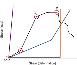
FIGURE 159-6 A stress-strain curve depicting a normal disc (black line), a fused spinal segment (purple line), and a dysfunctional motion segment (blue line). See Figure 159-3 for explanation of the different zones. Most current intervertebral metal-on-metal or metal-on-hard polymer prostheses are represented by the orange line (with a widened neutral zone until the limits of motion are reached.) Then the device reaches near infinite stiffness (vertical portion of curve). The most effective intervertebral prostheses should, perhaps, most closely approximate the black curve (A-B-C).
Nucleus Replacement Technologies
Nuclear implants are designed to replace the diseased nucleus pulposus. In theory, they restore disc height and anular tension, and assist in load transfer across the diseased disc.18 From a biomechanical perspective, the restoration of disc height and intradiscal pressures should result in the normalization of intact disc mechanics in terms of range of motion, neutral zone width, and energy dissipation.19 They are composed largely of viscoelastic materials and are either injected directly into the disc interspace or implanted through an open approach. Such devices require an intact anulus. Hence, large anular tears or defects are relative contraindications to this clinical strategy.
A limitation of this type of implant is the stress that it places on the end plate. Because most of these implants do not contact the entire end plate, they create end-plate contact pressure points that can lead to remodeling of the end plate. This can be associated with adverse outcomes. Furthermore, these implants may elevate shear strain in the anulus. These effects are related to the construction of the nuclear implant, where rigid nonconforming implants (e.g., polyetheretherketone [PEEK] devices) increase maximal shear strain and contact pressure points in the end plate, and conforming implants (e.g., viscoelastic hydrogel) do not.20 Another significant limitation of this technology is the risk of extrusion of these devices from the disc after implantation.21
Pedicle-Based Dynamic Stabilization Devices
Pedicle-based dynamic stabilization systems such as the Dynesys Dynamic Stabilization System (Zimmer; Warsaw, IN) are composed of “synthetic ligaments” suspended between pedicle screws with polyurethane sleeves incorporated over the ligaments. Dynesys is the only pedicle-based dynamic stabilization device approved for use today. The synthetic ligaments resist excessive flexion and the polyurethane sleeves limit extension. In extension, it unloads the intervertebral disc by a load-sharing mechanism. The FSU is stabilized in a relatively neutral alignment (as opposed to earlier designs, which induced lordosis). In theory, these devices are designed to add load-sharing ability to a diseased FSU. Several biomechanical studies have confirmed that implantation of these devices leads to reduced loading of the facets, decreased intradiscal pressures, and restoration of normal vertebral motion.22 Other studies have shown a decrease in adjacent-segment hypermobility and intradiscal pressures.23
Despite the initial positive results from pedicle-based dynamic stabilization technologies, several problems have become evident. The polyurethane sleeve is rigid, and if the sleeve is loaded between excessively distracted pedicle screws, kyphosis can be induced. Furthermore, the sleeves place the pedicle screws under significant shear stress in axial loading, and a relatively high number of screw breakages and pull-outs have been observed.24,25 It has been suggested that these devices actually may be a more effective adjunct to fusion rather than a motion-sparing strategy because several patients with these devices implanted went on to fuse at those segments.25,26
Other dorsal pedicle-based dynamic stabilization devices are in varying stages of development and clinical trials. Each uses unique mechanical strategies to overcome the known limitations of such FSU stiffening strategies. Each therefore harbors unique biomechanical nuances that diverge from those described for the Dynesys system. For example, an FEA of a new pedicle-based dynamic stabilization device called FlexPLUS (FlexSpine Pte Ltd.; Singapore) demonstrates a potential superior ability to offload the disc compared with Dynesys.27 The Universal Clamp (Zimmer SAS; Bordeaux, France) is a non–pedicle-screw-based system that uses a sublaminar polyester band anchored to a supralaminar rod. A cadaveric biomechanical study showed that it effectively reduced total range of motion while preserving normal motion at adjacent levels.28 This device would prevent the problems of screw loosening and breakage in the Dynesys system.
Total Disc Arthroplasty
Materials
Several materials are available for use with TDA technologies. Some models use a metal-on-metal interface (most commonly a titanium or cobalt-chromium alloy). This provides for the greatest amount of resistance to wear, but is associated with substantial axial load-related stiffness. Osteolysis from metal particulate debris may also be of concern in metal-on-metal implants.29 Other devices have a metal-on-hard polymer (usually polyethylene) interface, and are less resistant to wear than their metal-on-metal counterparts. Finally, some devices are constructed of pliable polymers in combination with hard polymers and/or metals. These devices use elastomers that are situated between metal end caps that make contact with the rostral and caudal end plates. These devices typically have the least amount of wear resistance and may be susceptible to failure at the metal-soft polymer interface.30
Metals and hard polymers are relatively rigid, especially compared with the gelatinous nucleus pulposus of the healthy disc. The metals and hard polymers that compose the ball-and-socket devices are nearly infinitely stiff in axial loading because these materials have a very low compliance. When axially loaded they tend to act independently of the magnitude of the load and therefore produce a linear stress-strain curve with a uniform slope (see Fig. 159-6). They are not as rigid as a bony fusion. However, they are not nearly as pliable as soft polymers or the intact disc. Material stiffness plays a significant role in offloading of the facets and dorsal elements after implantation. Compared with stiff core implants, implants that use a soft core have a higher propensity to share loads with the facet joints during axial loading because of their greater allowed range of motion. This has been shown to closely resemble intact physiologic forces shared between the healthy disc and the facets.31 Conversely, implants with high core rigidity bear the vast majority of the axial load alone, and do not share loads with the facets. This is concerning because it may produce a disuse osteopenia in the offloaded facets over time.31,32 High core rigidity can also lead to high levels of contact stress at the interface between the end plate and metal end cap, especially if they are slightly malpositioned.33 In general, implants that use soft polymer cores share axial loads with the facets but do not overload them, whereas rigid core implants nearly completely offload the facets. This may lead to higher stresses at the implant-bone interface and atrophy in the offloaded facets.
Design
Many current TDA models use a ball-and-socket design, very similar to prosthetic hips and shoulders. In some of these devices, the ball component is contained entirely within the socket and cannot be separated. This fixes the center of rotation of the implant (and the spinal segment in which it is implanted) in the center of the implant’s ball. Many of these implants may be placed with the ball directed rostrally (rostral center) or caudally (caudal center). However, there is no difference in the resulting range of motion with either implant.34 Unlike the IAR of a normal disc, this center of rotation does not move. Such a device should be placed as dorsally as possible within the disc space (to approximate closely the location of the normal IAR at rest); otherwise, significant stress will be placed on the dorsal osteoligamentous complex.35 Other ball-and-socket devices use a (usually polymer) semispherical core that acts as the ball and fixed metal sockets that fuse to the end plates. These devices do not have an absolute immobile center of rotation because there is a very small amount of core translation allowed. However, this amount of translation is so small that they are nearly identical to fixed ball-and-socket devices in terms of resulting stress to adjacent structures. These devices are most successful when they use a ball with a large radius of curvature (allowing for more translation and less rotation about the axis of the ball) and are placed as dorsally as possible within the disc space (to better replicate the normal IAR).18,36
Ideal Total Disc Arthroplasty
• Its structure will be nearly identical to that of a normal disc, in that it will contain a pliable, free-floating, soft core bound by a firm but flexible ring that both contains the gelatinous core and helps resist torsional forces. By these criteria, the ball-and-socket model does not replicate the anatomy of the normal disc.
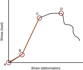
• The stress-strain curve of this device will be nonlinear and will closely replicate that of a normal disc (Fig. 159-7). The device will accommodate the initial axial load through deformation, but as the load gradually increases so will the device’s resistance to that load.
• The end caps of the device will readily bond with the end plates of the normal surrounding vertebrae.
• The device materials will have acceptable wear, fatigue, and failure resistance properties.
• The device will be constructed in such a manner as not to place undue stress on the surrounding intact spinal elements such as the facets and dorsal ligamentous complex. It will not excessively distract the disc space and will allow for the restoration of the normal variable IAR that moves in response to movement of the spinal unit. The device should restore disc height to a normal level, thereby taking stress off of the dorsal supporting elements.
• The normal range of motion of a healthy spinal unit will be restored by this device. It will not restrict movement of the spinal unit in any way, and it will preserve this motion for the life of the disc. It will not cause fusion at the disc space over time.
• In the unlikely case that the device fails, it should be easily removable and possibly replaceable.
Axelsson P., Johnsson R., Stromqvist B. Adjacent segment hypermobility after lumbar spine fusion: no association with progressive degeneration of the segment 5 years after surgery. Acta Orthop. 2007;78:834-839.
Benzel E.C. Biomechanics of spine stabilization. Rolling Meadows, IL: American Association of Neurological Surgeons, distributed by Thieme New York; 2001.
Ghiselli G., Wang J.C., Bhatia N.N., et al. Adjacent segment degeneration in the lumbar spine. J Bone Joint Surg [Am]. 2004;86:1497-1503.
Huang R.C., Wright T.M., Panjabi M.M., et al. Biomechanics of nonfusion implants. Orthop Clin North Am. 2005;36:271-280.
1. Matsumoto M., Okada E., Ichihara D., et al. Anterior cervical decompression and fusion accelerates adjacent segment degeneration: comparison with asymptomatic volunteers in a ten-year magnetic resonance imaging follow-up study. Spine (Phila Pa 1976). 2010;35:36-43.
2. Ishihara H., Kanamori M., Kawaguchi Y., et al. Adjacent segment disease after anterior cervical interbody fusion. Spine J. 2004;4:624-628.
3. Hilibrand A.S., Carlson G.D., Palumbo M.A., et al. Radiculopathy and myelopathy at segments adjacent to the site of a previous anterior cervical arthrodesis. J Bone Joint Surg [Am]. 1999;81:519-528.
4. Lee M.J., Bransford R.J., Bellabarba C., et al. The effect of bilateral laminotomy versus laminectomy on the motion and stiffness of the human lumbar spine: a biomechanical comparison. Spine (Phila Pa 1976). 2010;35:1789-1793.
5. Benzel E.C. Biomechanics of spine stabilization. Rolling Meadows, IL: American Association of Neurological Surgeons, distributed by Thieme New York; 2001.
6. Cannella M., Arthur A., Allen S., et al. The role of the nucleus pulposus in neutral zone human lumbar intervertebral disc mechanics. J Biomech. 2008;41:2104-2111.
7. Schmidt H., Kettler A., Heuer F., et al. Intradiscal pressure, shear strain, and fiber strain in the intervertebral disc under combined loading. Spine (Phila Pa 1976). 2007;32:748-755.
8. Heuer F., Schmidt H., Wilke H.J. The relation between intervertebral disc bulging and annular fiber associated strains for simple and complex loading. J Biomech. 2008;41:1086-1094.
9. Bartolomei J.C., Theodore N., Sonntag V.K. Adjacent level degeneration after anterior cervical fusion: a clinical review. Neurosurg Clin N Am. 2005;16:575-587. v
10. Ghiselli G., Wang J.C., Bhatia N.N., et al. Adjacent segment degeneration in the lumbar spine. J Bone Joint Surg [Am]. 2004;86:1497-1503.
11. Eck J.C., Humphreys S.C., Lim T.H., et al. Biomechanical study on the effect of cervical spine fusion on adjacent-level intradiscal pressure and segmental motion. Spine (Phila Pa 1976). 2002;27:2431-2434.
12. Pospiech J., Stolke D., Wilke H.J., et al. Intradiscal pressure recordings in the cervical spine. Neurosurgery. 1999;44:379-384. discussion 384–385
13. Abe E., Nickel T., Buttermann G.R., et al. Lumbar intradiscal pressure after posterolateral fusion and pedicle screw fixation. Tohoku J Exp Med. 1998;186:243-253.
14. Weinhoffer S.L., Guyer R.D., Herbert M., et al. Intradiscal pressure measurements above an instrumented fusion: a cadaveric study. Spine (Phila Pa 1976). 1995;20:526-531.
15. Axelsson P., Johnsson R., Stromqvist B. Adjacent segment hypermobility after lumbar spine fusion: no association with progressive degeneration of the segment 5 years after surgery. Acta Orthop. 2007;78:834-839.
16. Katsuura A., Hukuda S., Saruhashi Y., et al. Kyphotic malalignment after anterior cervical fusion is one of the factors promoting the degenerative process in adjacent intervertebral levels. Eur Spine J. 2001;10:320-324.
17. Kumar M.N., Baklanov A., Chopin D. Correlation between sagittal plane changes and adjacent segment degeneration following lumbar spine fusion. Eur Spine J. 2001;10:314-319.
18. Huang R.C., Wright T.M., Panjabi M.M., et al. Biomechanics of nonfusion implants. Orthop Clin North Am. 2005;36:271-280.
19. Arthur A., Cannella M., Keane M., et al. Fill of the nucleus cavity affects mechanical stability in compression, bending, and torsion of a spine segment, which has undergone nucleus replacement. Spine (Phila Pa 1976). 2010;35:1128-1135.
20. Dahl M.C., Ahrens M., Sherman J.E., et al. The restoration of lumbar intervertebral disc load distribution: a comparison of three nucleus replacement technologies. Spine (Phila Pa 1976). 2010;35:1445-1453.
21. Goins M.L., Wimberley D.W., Yuan P.S., et al. Nucleus pulposus replacement: an emerging technology. Spine J. 2005;5(Suppl 6):317S-324S.
22. Rohlmann A., Boustani H.N., Bergmann G., et al. A probabilistic finite element analysis of the stresses in the augmented vertebral body after vertebroplasty. Eur Spine J. 2010;19:1585-1595.
23. Strube P., Tohtz S., Hoff E., et al. Dynamic stabilization adjacent to single-level fusion. Part I: biomechanical effects on lumbar spinal motion. Eur Spine J. 2010;19:2171-2180.
24. Ianuzzi A., Kurtz S.M., Kane W., et al. In vivo deformation, surface damage, and biostability of retrieved Dynesys systems. Spine (Phila Pa 1976). 2010;35:E1310-E1316.
25. Grob D., Benini A., Junge A., et al. Clinical experience with the Dynesys semirigid fixation system for the lumbar spine: surgical and patient-oriented outcome in 50 cases after an average of 2 years. Spine (Phila Pa 1976). 2005;30:324-331.
26. Schwarzenbach O., Berlemann U., Stoll T.M., et al. Posterior dynamic stabilization systems: DYNESYS. Orthop Clin North Am. 2005;36:363-372.
27. Zhang Q.H., Zhou Y.L., Petit D., et al. Evaluation of load transfer characteristics of a dynamic stabilization device on disc loading under compression. Med Eng Phys. 2009;31:533-538.
28. Ilharreborde B., Shaw M.N., Berglund L.J., et al. Biomechanical evaluation of posterior lumbar dynamic stabilization: an in vitro comparison between Universal Clamp and Wallis systems. Eur Spine J. 2011;20:289-296.
29. Hallab N.J., Cunningham B.W., Jacobs J.J. Spinal implant debris-induced osteolysis. Spine (Phila Pa 1976). 2003;28(Suppl 20):S125-S138.
30. Enker P., Steffee A., McMillin C., et al. Artificial disc replacement: preliminary report with a 3-year minimum follow-up. Spine (Phila Pa 1976). 1993;18:1061-1070.
31. Kang H., Park P., La Marca F., et al. Analysis of load sharing on uncovertebral and facet joints at the C5-6 level with implantation of the Bryan, Prestige LP, or ProDisc-C cervical disc prosthesis: an in vivo image-based finite element study. Neurosurg Focus. 2010;28:E9.
32. Trouillier H., Kern P., Refior H.J., et al. A prospective morphological study of facet joint integrity following intervertebral disc replacement with the CHARITE Artificial Disc. Eur Spine J. 2006;15:174-182.
33. Lin C.Y., Kang H., Rouleau J.P., et al. Stress analysis of the interface between cervical vertebrae end plates and the Bryan, Prestige LP, and ProDisc-C cervical disc prostheses: an in vivo image-based finite element study. Spine (Phila Pa 1976). 2009;34:1554-1560.
34. Rousseau M.A., Cottin P., Levante S., et al. In vivo kinematics of two types of ball-and-socket cervical disc replacements in the sagittal plane: cranial versus caudal geometric center. Spine (Phila Pa 1976). 2008;33:E6-E9.
35. Galbusera F., Anasetti F., Bellini C.M., et al. The influence of the axial, antero-posterior and lateral positions of the center of rotation of a ball-and-socket disc prosthesis on the cervical spine biomechanics. Clin Biomech (Bristol, Avon). 2010;25:397-401.
36. Rousseau M.A., Bonnet X., Skalli W. Influence of the geometry of a ball-and-socket intervertebral prosthesis at the cervical spine: a finite element study. Spine (Phila Pa 1976). 2008;33:E10-E14.