Chapter 21 Biomechanical Testing
Background
In the second half of the 20th century, the research area of biomechanics encompassed a problem that, at one time, was of interest to Leonardo daVinci–the human spine.1 In the 1970s and 1980s, in particular, there was a rapid increase in the biomechanical analysis and quantitative understanding of the anatomy of the spine and clinical issues related to its treatment.2–8 This new insight enabled researchers to design and develop devices that aimed to restore normal physiologic movement.9,10 However, one of the unforeseen consequences of this flurry of scientific activity was a lack of standards.9,11–13 Depending on the laboratory and the application, devices were being evaluated under different conditions, making comparison difficult. Limitations related to the peculiar nature of the spinal anatomy and testing made standardization difficult. Eventually, however, consensus was achieved and standards evolved.9,13 From the economic point of view, spine biomechanics seems to have delivered on its promise. According to Epsicom, a global market research company, the spinal implant market saw a growth of about 8 billion dollars in 2008. It is estimated that by 2012, the worldwide spinal market will realize revenues of 10 billion dollars.
Another avenue of inquiry has been aiming at resolving clinical issues without the use of any “mechanical” devices. This field, tissue engineering, has started to show great promise in the field of spine biomechanics. With U.S. federal funding available for stem cell research, a global market of 4.8 billion dollars, and about 200 companies working on designing newer and better orthopaedic biomaterials, the future is bound to see a growing influence of tissue engineering in spine deformity correction. Although challenges exist,14,15 our understanding of issues related to the regeneration of the nucleus pulposus16,17 and anulus fibrosus18 has increased manifold. As a case in point, much interest is being paid to scaffolding.19,20 Interested readers are advised to review a classic publication by Lanza et al.21
Back- and neck-related issues led to 86 billion dollars in health care expenses in the United States from 1997 to 2006.22 In the same decade, an increase of nearly 50% was found in the number of patients seeking spine-related healthcare expenditure.22,23 In parallel, a 65% increase in health care expenditure in general was measured. Numerous types of surgical procedures are performed on the spine to prevent further deterioration of spinal components or escalation of pain, and various devices are being conceived, designed, tested, and implanted to aid in these treatments. Most of this instrumentation—for example, interlaminar hooks, transpedicular screws, interbody spacers, and cages—is relevant to spinal fusion.24 The goal of such instrumentation is to fuse two or more vertebrae together to eliminate pain and allow the patient to return to normal activities. Alternatives to fusion include the hydrogel-based prosthetic nucleus, the liquid polymer-based nucleus, motion preservation devices, and artificial discs.24
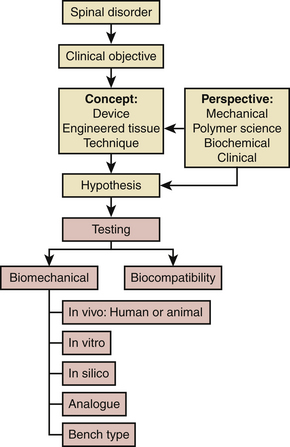
As shown in Figure 21-1, almost everything that is done in biomechanical testing flows from an existing spinal disorder and the perspective of the individual researcher. We do not claim that this algorithm is comprehensive, a case in point being the regulatory part of the process. Other variables include the types of perspectives (e.g., material science), concepts, and tests. Based on his or her perspective and the clinical objective, a researcher may come up with a concept of a solution, for example, a tissue-engineered nucleus for a damaged intervertebral disc. This concept is tested, proving or disproving a predefined hypothesis. The nature of the specific test may be purely mechanical, biomechanical, or based on biocompatibility. In the case of an engineered nucleus, for example, a test could be any of these (except in vivo, which is rare).20 For the nucleus, such a test could involve measurement of motion after surgical implantation in a cadaveric spine model or, perhaps, a purely mechanical study assessing its compressive modulus (i.e., a bench-type test). On the other hand, if the clinical objective is being met from a mechanical perspective, resulting in a mechanical device, the range of tests would include pure mechanical tests such as fatigue and wear tests. Determination of the chemical composition following corrosion and wear testing complements these mechanical tests. At some stage, testing using animal spine models, cadaveric spines, analogue spines, or computer simulations (i.e., in silico), and, eventually, clinical trials on human subjects, will follow.
Although all types of testing modalities are important in the process of concept evaluation and assessment as shown in the algorithm, this chapter focuses on three: bench type; in vitro, or, more appropriately cadaveric; and in silico testing of devices and engineered tissues under the overarching term of biomechanical testing. Moreover, we differentiate between construct testing and implant testing. The terminology, testing procedures, apparatuses, and protocols that have evolved over the years in testing of spinal implants also are reviewed. We also speculate regarding future prospects for biomechanical devices and note the areas that may need more attention from the spine biomechanics community.
Bench-Type Tests for Approval by the U.S. Food and Drug Administration
To evaluate the endurance and strength of orthopaedic implants, various mechanical and materials testing protocols have been proposed by ASTM International (formerly known as the American Society for Testing and Materials) as standards for testing of such devices under different dynamic and static loading profiles (Table 21-1). These protocols allow researchers to estimate the static strength and fatigue limits of an implant assembly and its individual components in a consistent way, thereby enabling a fair comparison of results. Guidelines also are proposed by ASTM and the International Organization for Standardization (ISO) for evaluation of fixation of the parts and loosening effect at the interface of implant components.
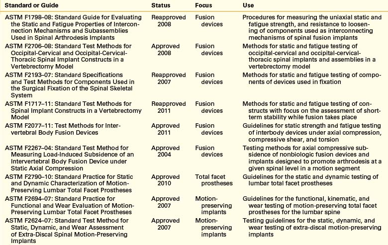
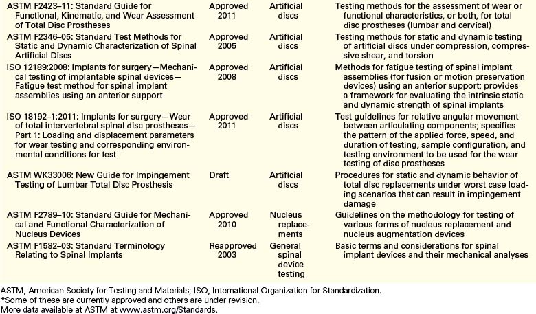
Data from these standardized tests are used by the medical device industry to seek approval for commercial distribution of devices from the U.S. Food and Drug Administration (FDA). Medical devices are categorized by the FDA in classes—class I, class II, and class III—based on the degree of regulatory control. Most class II devices, such as the pedicle screw–based instrumentation systems, require submission of a Premarket Notification 510(k), whereas class III devices—devices that pose a significant risk of illness or injury—require premarket approval (PMA; Fig. 21-2). Motion preservation systems, for instance, are categorized as class III devices. The test protocols listed in Table 21-1 pertain to class II devices. Class III devices also may be assessed using these protocols, but approval for commercial distribution of such devices requires submission of clinical data in support of the manufacturers’ claims.
Similar tests sometimes are carried out on ligamentous motion segments. These tests include subsidence tests, pull-out25 or push-out testing of pedicle screw systems26 and cages, respectively, and fatigue tests. Subsidence is a phenomenon in which one or both vertebral end plates adjacent to the implant collapse and allow the implant to move in, increasing the probability of deformity progression and worsening of the fusion.27 Static, quasi-static, or dynamic tests such as pull-out tests also are performed on pedicle screws to measure bone-implant interfascial strength under such forces. New ASTM guidelines are available for the assessment of facet replacement technologies, wear characterization, and motion preservation systems such as artificial discs.
Wear testing is carried out on a wear simulator (Fig. 21-3). One such simulator (MTS Bionix, MTS Systems Corp., Eden Prairie, MN) consists of six active stations (test stations) and one control station.28
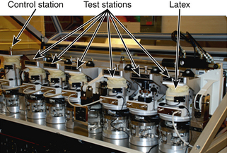
Polymeric components in a disc replacement device are soaked in a bath for a week before the test. These are then cleaned and dried in accordance with ASTM F2423-05 (see Table 21-1). Flexion-extension, lateral bending, and rotations are simulated under a constant preload as per ASTM standards. Mass measurements are performed both before and after testing to assess the wear rate. Particulate characterization and element contributions are evaluated using computer- controlled scanning electron microscopy.
Analysis
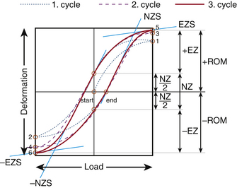
Elastic zone: The amount of total deformation that offers resistance to the applied load. It is measured by evaluating the tangent to the curve at the load that causes maximum deformation (Fig. 21-4; points 5 and 6).
Elastic zone stiffness: This is the stiffness that characterizes the amount of elastic (or recoverable) deformation of the specimen.
Energy dissipation: To characterize the viscoelasticity or plasticity of the specimen being loaded, the area enclosed by the load-displacement curve is evaluated. This quantity provides a measure of the dissipated energy.
Neutral zone: The amount of unrecovered deformation once the specimen is under no load. In cycle 3 shown in Figure 21-4, NZ is the neutral zone. It also may be defined as the part of the range of motion wherein the specimen offers the least resistance to the applied deformation.
Neutral zone stiffness: The stiffness of the specimen in the neutral zone, determined by the slope of the load-displacement curve at the point of no deformation
Preconditioning: Cycles of load applied to the specimen—intact or otherwise—to mitigate the impact of the viscoelastic nature of the tissues. From Figure 21-4, cycles 1 and 2 are the preconditioning cycles.
Range of motion (ROM): The linear or the angular distance that a specimen (intact or injured or construct) travels in a plane with the application of load in that plane. From the load-displacement curve of Figure 21-4 the ROM can be calculated as (+ROM) − (−ROM).
Relative range of motion (RROM): The relative motion for the entire spine or a segment or even a vertebral body with respect to the static mounting platform
Sigmoidity: A measure of the non-linearity present in the mechanical behavior of the specimen,29 calculated as the ratio of the neutral zone stiffness and elastic zone stiffness.
Stiffness: The mechanical resistance of a specimen to an applied load, measured by the slope of the load-deformation or load-displacement curve along a linear region or regions in a nonlinear curve.
In Vitro Testing
The human spine is a complex structure composed of hard and soft, active and passive tissue. This structure has multiple degrees of freedom at each one of several joints formed by intervertebral discs. Ideally, from a biomechanical and biochemical point of view, the most physiologically relevant model for testing the efficacy of a device, surgical technique, or engineered tissue is the human spine of a live subject. However, this is not a practical option. In vitro testing offers significant advantages, even though factors such as intra-abdominal pressure and muscular forces are hard to replicate.13 In vitro studies have the advantages of the possibility of standardization, ease of estimation of the impact of a surgical procedure, or a simulated injury or stabilization using an implant, because the loads can be varied with relative ease. Such protocols enable researchers to compare different devices designed and developed for the same clinical requirement. Once the device components have been tested using protocols cited in Table 21-1, in vitro testing brings their performance evaluation closer to in vivo use in patients.
Terminology
Some of the terms most commonly used in in vitro studies are defined in this section.
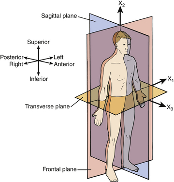
Anatomic planes: To make it possible to specify the locations and angular configurations of the vertebrae, a coordinate system is defined that has three mutually orthogonal planes: the sagittal plane (side view), the frontal or coronal plane (front view), and the transverse plane (top view). Figure 21-5 shows the three anatomic planes along with the terminology for forward/backward, left/right, and up/down directions.30
Center of rotation (COR) or instantaneous axis of rotation (IAR): In a general planar motion, the axis of rotation may move. If this movement is broken down into steps, the instantaneous axis of rotation can be identified at every step of the motion. Such an axis may pass through the rigid body (in the case of a spinning top) or lie outside it (in the case of the flexion or extension of a spinal segment). To specify the IAR completely, one must provide three numbers: two for translations and one for rotation or any combination of these parameters. The IAR is specified only for plane motion, not for 3D motion—that is, there is no IAR for lateral bending or axial rotation because these involve 3D motion, whereas flexion and extension are considered planar motions for all practical purposes.31 However, there is evidence that relatively small coupled motions are present even in flexion and extension.32
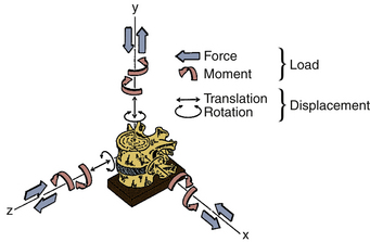
Coordinate system: An orthogonal, right-handed, 3D reference system that makes it possible to define the position and motion of vertebral bodies. In Figure 21-6, the x, y, and z axes represent the three orthogonal directions with the origin of the coordinate system located at the base.29 The positive x-axis represents the left lateral direction, whereas the positive y-axis represents the rostral direction and the positive z-axis represents the ventral (anterior) direction. Such a system is known as a global coordinate system. A reference system can be local, however, in the sense that it allows for the position and motion of rigid bodies to be defined with respect to each other. Wilke et al.29 suggest, for most cases, “the mid-point in the frontal plane of the dorsal (posterior) margins of the two adjacent” vertebral endplates as the origin of the local coordinate system.
Degrees of freedom: The number of independent coordinates necessary for complete specification of the position of a particle or a rigid body in space. Under an applied load, a rigid body may move, in total, in six directions: that is, it has 6 degrees of freedom: three translational and three rotational. In comparison, a particle can have only 3 translational degrees of freedom. A general motion by the vertebra may be broken down into six components of these pure motions.
Envelope of the helical axis of motion: The surface generated by various helical axes of motion of a moving rigid body.
Follower load: A compressive load applied to the spinal segment (through strategic points on each vertebral body) that aims at minimizing the coupled flexion-extension changes in motion and shear force in the disc by following the COR of each functional spinal unit of a specimen.33 In cadaveric experiments, a compressive follower load is applied to the specimen to mimic the upper body weight and muscle force application on the lumbar spine. The application of follower load works well only in flexion and extension.31 Bilateral cables are used to apply this load.
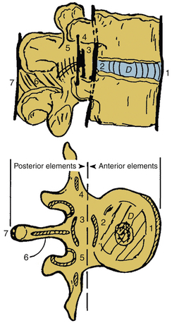
Functional spinal unit (FSU) or motion segment: The macrostructural unit of the spine, representing the broad mechanical behavior of two adjacent vertebrae, ligaments, the intervening intervertebral disc, and zygapophyseal (or facet) joints. Studying the biomechanics of an FSU is convenient and relatively straightforward. Figure 21-7 shows with an FSU with an intact intervertebral disc.
Helical axis of motion (HAM) or screw axis motion: As an alternative to x, y, and z coordinates and Euler angles, motion of a rigid body can be decomposed into a translation and rotation about the axis of translation. This axis is known as the screw axis or helical axis of motion. It can be visualized by observing the motion of a screw being driven into a pedicle of a vertebra. As the screw is being tightened, it not only rotates but also translates into the pedicle along an axis running through the screw. Consistent with the 6 degrees of freedom for a freely moving rigid body in the 3D coordinate system, six scalar quantities are required to define 3D motion using HAM: two for the orientation of the axis, two for its position, one for the amount of rotation about the axis, and one for the amount of translation along the axis. The helical axis of motion, although difficult to visualize, particularly for clinicians, may provide quality of motion when compared with an end-point parameter such as range of motion (ROM), which determines simply the quantity of motion. For example, it recently was found that axial rotation causes the helical axes to migrate dorsally, correlating well with high facet joint forces.34
Injured specimen: A spine specimen with existing or simulated clinical pathoanatomy in terms of injury of ligaments, disc(s), and/or bony tissue
Instability: From a purely mechanical perspective, instability of a specimen undergoing in vitro testing may be characterized by a significant change in the range of motion relative to the intact specimen, for example, 3.5 mm of translation will make a specimen unstable.35 Instability may be related to spinal degeneration and pain.
Intact spine specimen: A portion of the fresh-frozen cadaveric spine consisting of one or more contiguous functional spinal units with intact ligaments and disc(s). Fascia, muscles, and fatty tissues are dissected.
Muscle force simulator (MFS) or replicator (MFR): A system that simulates muscle forces on a spinal motion segment. Unfortunately, this experimental setup was found to be so arduous that repeating similar experiments became unrealistic.36,37
Plane motion: Motion characterized by translation(s) and/or rotation(s) in a single plane. For instance, flexing the vertebra (or, in other words, forward bending) is a plane motion occurring in the sagittal plane. In Figure 21-6, flexion will be fully specified in the y-z plane. Flexion of the vertebral body at the top will involve not only rotation but also translation. Furthermore, there may be some varying degree of out-of-plane motion as well.38
Primary and coupled motion: In terms of plane motion, the motion occurring in the same direction as the one in which the load is applied is known as primary motion. The out-of-plane motion is known as coupled motion.
Primary loading directions: In most cases, spinal motion segments are tested in the following directions: flexion-extension, left-right bending, and left-right axial rotation. Pure moments are applied in one of these directions, and motion is measured. In a complex system such as a spine, application of a pure moment results in six motions. So, in an experiment that involves applying 6 pure moments on a segment, 36 load-displacement curves exist. A specimen may be loaded in a number of ways, which may be understood in terms of their orthogonal constituents or components in a global coordinate system. Reaction loads, for example, can be understood as being composed of three forces and three moments acting at a point of interest, such as the base of the specimen shown in Figure 21-6.
Relative motion: The motion of a rigid body with respect to another rigid body, for example, the motion of a vertebral body with respect to an adjacent vertebral body. However, the motion of a vertebral body relative to the static floor is absolute (or global) motion.
Rigid body: A system of particles in which the distance between any two particles remains unchanged regardless of external loads (forces or moments) applied. In other words, a rigid body does not deform. A rigid body is an idealization of a solid body of finite dimensions for the purpose of analysis. In construct testing, vertebrae are considered as rigid bodies.
Rotation: The vertebra in Figure 21-6 can rotate about three orthogonal axes in a clockwise (positive) or counter-clockwise (negative) direction. Curved arrows in Figure 21-6 show these degrees of freedom. In a 3D global coordinate system, Euler or Cardan angles specify the rotation of a rigid body.
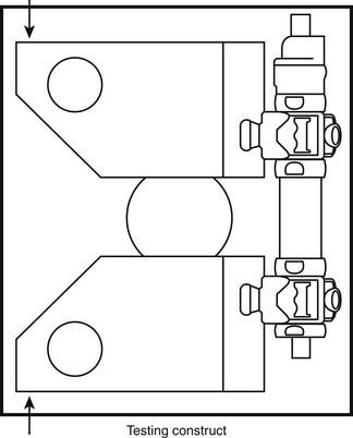
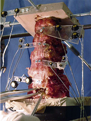
Spinal construct: A portion of the spine instrumented with an implant or several implants of interest. Its characteristic motion is different from that of the intact spine. Figure 21-8 shows a spinal construct prepared for testing. The vertebra at the bottom is embedded in a polyester resin or low-melting-point alloy of choice for attachment to the test fixture, and a loading frame is rigidly secured to the superior-most vertebra for the application of loads.
Spine loading simulator: An apparatus to hold spine specimens and test them under different loading scenarios. Several research groups have come up with various designs of a loading simulator, ranging from fully automated to a system of pulleys and dead weights, for manual application of loads.
Three-dimensional motion: The type of motion seen in a rigid body in a global coordinate system that is free to translate or rotate in one or more of its six degrees of freedom
Translation: As shown in Figure 21-6, a vertebra can translate along three axes, that is, positive or negative x, y, and z axes. These are shown by straight arrows.
Specimen Selection
Species
Several functional animal models have been evaluated for testing the efficacy of spinal implants.29,39 Calf, sheep, and baboon spines have been used previously. It has been found that larger primates such as baboons are needed for simulating the load, although calf and sheep spines may be valid for range of motion studies. Animal models have several limitations, including appropriate shaping and sizing of implants for the animal tissue, comparable human surgical technique, and differences in the functional anatomy and motions between the human and the animal spine.
Human cadaveric spine models have their own set of limitations. The spine specimens tend to be from elderly individuals who may have suffered some sort of degeneration of the bone (e.g., osteoporosis) or disc (e.g., stenosis) or the spine itself (e.g., spondylolisthesis). Specimens in which such degeneration is apparent are excluded.29
Testing Environment
Two key factors that may influence the mechanical performance of the construct are temperature and humidity, which is maintained by constant spraying of an appropriate solution, either manually at regular intervals or in an automated fashion using a peristaltic pump. Most experiments are carried out at room temperature. It is known that body temperature causes a slight expansion in ligaments, whereas discs and tendons creep at a higher rate.42 Evidence for changes in the extensibility and fatigue life of bone also exists.42 Wilke et al. showed that moisture plays a significant role43 and recommended intermittent spraying of specimens with 0.9% saline.29
Specimen Handling and Preparation
Preparation
Before testing a spinal segment, a specimen is thawed at room temperature for several hours. Preparation may involve casting in resin, attachment of light-emitting diode (LED) marker plates for motion measurement, surgical insertion of implants, guides for follower load cables, and insertion of transducers for facet joint load or disc pressure measurement.44 A surgical procedure is simulated to represent a clinical scenario as closely as possible. Such procedures may be necessary to imitate a pathologic state. For instance, a vertebral compression fracture may be simulated as a wedge-shaped excision.45,46
Testing Apparatus
Spinal Loading Simulator
The spinal loading simulator allows 6 degrees of motion for a spine segment. Different types of simulators have been designed: pulley- and cable-based,47–49 orthogonal stepper motor–based,50,51 robotic arm–based,52–56 Stewart platforms,57 and others.58,59 These systems use different control paradigms: constrained load control, unconstrained load control, and displacement control.60 More recently, newer simulators have been designed60–62 to minimize apparatus-related errors. These systems aim at applying pure moments on the spine,9 because applying forces on the spine results in nonuniform loading of the construct, rendering a direct comparison of results challenging. The literature, however, is not clear regarding the accuracy and precision of each of these systems. There is evidence that the apparatus may induce significant artifacts.63 Although most researchers acknowledge the lack of standardized protocols, a gold standard still remains elusive.
Motion Measurement System
The motion measurement system allows the measurement of 3D motion of a set of markers. A plate carrying at least three non-collinear markers is screwed into a vertebra to assess the rigid body motion of that vertebra. All six motions—three translations and three rotations—are evaluated, first in a local coordinate system and then in a global coordinate system. This motion measurement system, like the load simulator, may have inherent errors associated with the camera system or the marker configuration.61 Publishing the accuracies inherent to the various setups (including marker configuration) would be beneficial to the scientific community in general.
Other transducers also provide relevant information.13 For instance, film force sensors, pressure sensors, accelerometers,13 buckle transducers, and strain gauges64 have been used to measure facet joint loads, disc pressure, and vibration in the spine and strain in the instrumentation,65 respectively.
Testing Methods
Static Strength Testing
Until the early 1980s, spinal constructs were tested destructively. These strength tests involved loading an intact spine until some type of failure occurred (either plastic deformation or fracture).66 High ultimate strength was considered to correlate with higher stability.11 Parameters like load-to-failure, work-to-failure (or energy-absorbed-to-failure), and stiffness are determined in this type of test, but these are relevant only to catastrophic failures, which are rare. Fatigue failure of implants (e.g., pedicle screw instrumentation) is more common,67 leading to the evolution of nondestructive testing of spinal segments under subfailure loads. However, cyclic testing rarely produced any failures of implants in the laboratory11 because tissue properties change in the time required to carry out such tests.11 Wilke et al. recommend that the total duration of the test be no more than 20 hours.29,43
Stability Testing
Stability (or rigidity) testing involves loading the construct to levels that do not result in an apparent failure of any of the components of the construct. Stiffness of the construct may be measured in terms of Newton per millimeter (N/mm) in force-displacement tests or Newton-meter/degree (N-m/deg)9 in cases of pure moment application and angular motion. Although instability has been used to define the inverse of stability, we recommend flexibility to determine a motion for an applied load. Flexibility is measured in mm/N or deg/N-m as the case may be. The stiffness protocol and flexibility protocol68 come under the umbrella term of stability testing, but the stiffness protocol entails application of one component of motion at a time to assess loads applied on the vertebra and other components of the FSU. The flexibility protocol involves applying one component of load at a time to determine intervertebral motions.
Hybrid Testing
A hybrid protocol was propounded by Panjabi31,69,70 as a part of stability testing in order to measure changes on the adjacent levels due to a surgical procedure. The protocol is a four-step procedure.
Postsurgery
Uninhibited pure moments are applied to the construct until the total ROM of the construct is equal to the ROM of the intact spine segment. This protocol allows testing for the assessment of adjacent level effects commonly observed in fusion surgical procedures.69 The argument used in support of this protocol is that, postsurgery, patients undertake the same day-to-day activities that they would carry out presurgery, thus actualizing the same range of motion.55
Load versus Displacement Control
Most cadaveric testing has been performed using load as the control variable, pure moments, in particular, because the magnitude of the bending moment does not vary as a function of the spinal level or even the state of the spine—be it intact, injured, or stabilized.9,71 However, Edwards et al.72 favor displacement-controlled testing of spinal segments under combined displacements because in vivo motion can be simulated accurately in the laboratory environment, whereas in vivo loads are unknown. The disadvantage of complex loading patterns in displacement-controlled testing, however, makes this method less straightforward. Also, comparison with simulated injuries and stabilizations is not possible. However, it may be beneficial to perform displacement-controlled testing after collection of basic load-displacement data from load-controlled testing.71
Additional Applications of Construct Testing
Although the overall methodology of testing remains the same as described earlier for animal specimens, the magnitude of parameters selected will change. Pre- and postsurgical biomechanical and histomorphometric analyses also have been performed on animal spine specimens ex vivo as a function of time in addition to characterization of biomechanical parameters.73 Spine specimens also are used to delineate the cyclic74 and viscoelastic behavior of young and old spines.75 Individual spinal components also may be tested to determine their characteristics, such as the load-displacement behavior of spinal ligaments or vertebral body strength (intact spine vs. one that has a fractured vertebra vs. one that has undergone surgery like kyphoplasty or vertebroplasty).40
Analogue Tissue Testing
The three main categories of nucleus replacement devices are hydrogel-based, polymer-based, and mechanical. Several types of mechanical tests usually are carried out on these devices. Pure compression tests are performed to determine the compressive modulus for the device or the “apparent” modulus at a given load. Some studies report stress relaxation data.16,76 Displacement-controlled fatigue testing also is carried out for several million cycles.77–79 Disc height changes80 and typical viscoelastic parameters such as loss tangent, viscous modulus, and elastic modulus also are estimated in these studies.81 Testing is conducted while keeping the device either radially unconfined or confined in a constant-temperature bath filled with Hanks’ balanced salt solution or a phosphate-buffered solution.16,78 Cadaveric axial compression, extrusion tests, and regular loading in all three anatomic planes also are performed to test the integrity of the device. Failure load and strains are assessed from such tests.77,79 Although similar tests are carried out on anulus replacement devices, destructive tensile testing also is carried out to judge the tensile strength and elongation of the device.82
Scaffolds provide a stable structure for tissue growth. A scaffold is a 3D collagen matrix that allows cells (usually multi- or pluripotent stem cells) to attach, divide, proliferate, migrate, and differentiate into a specific phenotype.83 Certain growth factors may be necessary for these functions to take place while nutrient supply is maintained.81 Certain cell types have been found to be capable of detecting the stiffness of the surrounding substrate, and such sensitivity (mechanosensitivity) has been shown to affect mesenchymal stem cell differentiation.20 Chan and Leong20 stress the importance of understanding the impact of interfascial shear stress. Most tissue engineering work specific to the spine has been directed toward the goal of engineering an intervertebral disc in a laboratory setup. However, the challenge lies in fine-tuning the stiffness of the scaffolding for both the nucleus and the anulus replacement. Some of the key issues that still must be resolved include matching the complex in vivo tissue loading, porosity, nutrient supply, cell supply, viscosity and stiffness, and the state of disc degeneration of the native disc.14
In Silico Testing
Background
Over the last few decades, FE analysis (FEA) has served well in studying the biomechanics of the spine in different physiologic circumstances such as growth, injuries, trauma, and surgical procedures. In these studies, the FE models of spine segments have predicted changes in biomechanical parameters such as load sharing, stress distribution, and segmental kinematics at sections of interest.
Model Development
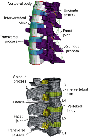
FE models can be created in several ways. If a tissue or pathoanatomy is of significance, the current approach is to develop the model based on existing CT or MRI scans of the area. Figure 21-9 shows the steps that were taken to develop an FE model of the L3-S1 lumbar spine segment.84 First the CT and/or MRI scans of the subject’s lumbar spine were acquired. Transverse scans, usually taken at 1-mm intervals, were used to develop the geometry. A node grid was superimposed over each transverse image with appropriate node density to represent a precise geometry of the cross-section, specifically at the outer boundaries and interfaces. The grids were assembled to create a cloud of nodes that represented the 3D geometry of the entire section. Next, the nodes of each of the two adjacent sections were interconnected using 3D hexagonal (brick) elements to develop a solid structure. Facet joints were simulated using GAPUNI contact elements available in Abaqus (Simulia, Providence, RI). Rebar elements were used to mimic the anulus fibrosus component of intervertebral discs. Finally, the ligaments were simulated by 3D truss elements. After development of the geometry, an appropriate material property was assigned to each group of elements, representing associated structures in the spine such as vertebral bodies, capsular joints, intervertebral discs, and ligaments.84,85
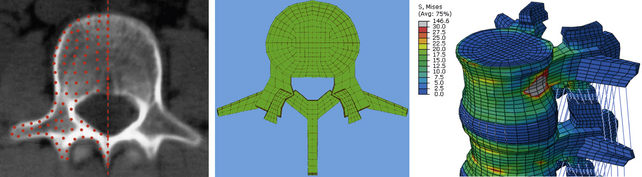
FIGURE 21-9. Steps in the development of a finite element model of a lumbar spine segment using CT scans.
The kinematics of this FE model was validated by comparing its segmental rotations with data obtained from an in vitro experiment under similar loading and boundary conditions. Other parameters such as center of rotation and intradiscal pressure (IDP) also were compared for further validation of the model.86 This validated FE model was used in several biomechanical studies for investigation of biomechanical changes in the spine (e.g., load distribution, kinematics, stresses, and strains) after simulation of surgical and implanted cases.84,87,88 Figure 21-10 shows FE models of C3-7 and L3-S1 spine segments that were developed using this technique.
• It is not practical to obtain a model with geometry that thoroughly matches that of the real spine, but the geometric model must be as close to the actual geometry as possible, specifically at the locations where the geometry may have a significant impact on biomechanical outputs. Contact definition, intervertebral discs, and angle of the articular facet joints are examples.
• Cancellous and cortical regions of the bone should be designated with appropriate thickness and material properties across the vertebrae.
• Each aspect of the model must be assigned a proper element type. For example, bony regions and discs usually are assigned hexagonal or tetragonal elements, whereas for ligaments, 3D truss or beam elements connecting two aspects of the model are suggested. Ligaments can be modeled as a bundle with appropriate cross-sections for each fiber. A no-compression behavior should be assigned to each such fiber to ensure that only tensile loads are allowed.
• The intervertebral disc should be modeled as a nonhomogenous composite structure including an amorphous matrix reinforced by collagenous fibers. Proper element types should be used for each area of the disc. For example, the nucleus can be modeled with noncompressible fluid elements. On the other hand, the anulus may be modeled with solid, elastic elements that are assigned mechanical properties and volume fraction. These elements, at appropriate angles, represent the radial variation of the collagenous fibers. It may be necessary to change element types to model a degenerated disc.
• A proper contact profile assignment is required at the articulating surfaces of the facet joints.
• In case a nonstatic simulation, such as dynamic loading, impact, long-term creep, or wear, is of interest, the time-dependent behavior of elements, materials, contact profile, and boundary conditions must be input into the model prior to any simulation run.
• The loads and boundary conditions also must be defined correctly. For example, to simulate physiologic loading such as flexion-extension, left-right bending, and left-right axial rotation, the most caudal section of the model (e.g., S1) should be fixed in all degrees of freedom, and pure bending moments should be applied to the most cephalad vertebra (e.g., L3). To simulate the upper body weight, a follower load may be applied to the spine using actuator-type connector elements. These elements can be activated through each loading step to apply any compressive force across segments.49,86
In Silico Study
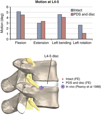
Figure 21-11 shows the FE spine that was modified to simulate the implantation of a novel 360-degree motion preservation system at the L4-5 segment.88,89 FEA was performed to investigate whether this motion preservation system would be able to regenerate the kinematics of the intact spine. The 360-degree system included a pair of posterior dynamic stabilizers (PDS) matched with dorsal discs. The surgical procedure for placement of the implants required removal of the entire nucleus and partial anulus, total bilateral facetectomy, and removal of dorsal longitudinal ligaments. Surgery was simulated by removal of associated elements at each section. After placement of the implants, sliding contacts were defined between implant components while rigid fixations were simulated at the interface of bone with pedicle screws and discs. Both intact and implanted models were subjected to the same boundary conditions and loading profiles, including a 10-Nm bending moment plus a 400-N follower load. The kinematic results predicted by the model showed that in most loading conditions (except in axial rotation), the implanted segment had motion close to that of an intact segment (see Fig. 21-11).
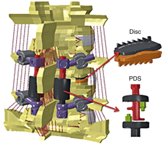
FIGURE 21-11. Finite element model of L3-S1 spine implanted with a posterior dynamic stabilization (PDS) and disc system at L4-5.
The extension-to-flexion center of rotation (COR) remained close to intact after replacement of the 360-degree system, which indicates that the quality of motion also was preserved after implantation (Fig. 21-12). Both CORs were found to be within the in vivo range.
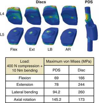
The stress distribution contour and maximum von Mises stress at PDS and disc are shown in Figure 21-13. The maximum stress ranged from 69 MPa to approximately 146 MPa in PDS and 166 to 244 MPa in discs.
Clinical Objective
Decisions on the type and length of specimen, types of tests and protocols, types of statistical analysis, and finite element analysis, among other variables, are made keeping in mind the clinical objective. Some of these decisions may have to be made within the existing standards and requirements of the FDA.39 In vitro tests may have different clinical objectives. For example, they may be done to (1) perform a comparative study with an existing standard or to evaluate the performance of a device by measuring relevant parameters, (2) quantify a clinical or surgical procedure using existing or novel parameters using existing or novel protocols relevant to its eventual application, or (3) quantify physiologic data, for example, biocompatibility of a new device, disc height postmortem,42 and spinal curvature in a given pathology, among several other parameters.13
Summary
With emerging standards, rapid progress in the device market, an aging population, and continued growth in the areas of tissue engineering and computational efficiency, testing of spinal implants not only will remain an important step in the path90 along which a device makes its way to the clinic but also will have a larger role to play. A strong relationship among tissue engineers, clinicians, the finite element analysis community, and mechanical testing experts will be crucial in meeting the challenges of the future. We believe that the spine biomechanics community will benefit greatly by agreeing upon a standard phantom spine made from nondecomposable materials.61,91–93 Using such a specimen, research groups may document accuracies of their loading methods and measurement systems, making a reasonable comparison of results possible. This approach may also be suitable for the training of students, residents, and fellows.
This chapter has provided an overview of the test protocol–related practices in the area of spine biomechanics. Interested readers may find other reviews of interest, particularly those by Goel et al.,24,31,39 Wilke et al.,29 and Panjabi et al.9,10,32,94 Literature reviews of protocols in the context of specific devices 24,95 also have been published.
Acknowledgment.
Thank you to Lars Gilbertson, PhD, for his input regarding the production of this chapter.
Ashman R.B., Birch J.G., Bone L.B., et al. Mechanical testing of spinal instrumentation. Clin Orthop Relat Res. 1988;227:113-125.
Goel V.K., Kiapour A., Faizan A., et al. Finite element study of matched paired posterior disc implant and dynamic stabilizer (360° motion preservation system). SAS J. 2007;1(1):55-62.
Goel V.K., Panjabi M.M., editors. Roundtables in spine surgery. Spine biomechanics: evaluation of motion preservation devices and relevant terminology, Vol 1. St. Louis, MO: Quality, 2005.
Goel V.K., Weinstein J.N. Biomechanics of the spine: clinical and surgical perspective. Boca Raton, FL: CRC Press; 1990.
Panjabi M.M., Oxland T.R., Yamamoto I., Crisco J.J. Mechanical behavior of the human lumbar and lumbosacral spine as shown by three-dimensional load-displacement curves. J Bone Joint Surg [Am]. 1994;76(3):413-424.
Puttlitz C.M., Goel V.K., Pope M.H. Biomechanical testing sequelae relevant to spinal fusion and instrumentation. Orthop Clin North Am. 1998;29(4):571-589.
Wilke H.J., Wenger K., Claes L. Testing criteria for spinal implants: recommendations for the standardization of in vitro stability testing of spinal implants. Eur Spine J. 1998;7(2):148-154.
1. Panjabi M.M. The stabilizing system of the spine. Part I. Function, dysfunction, adaptation, and enhancement. J Spinal Disord. 1992;5(4):383-389. discussion 397
2. Bogduk N. Proceedings: the posterior lumbar muscles and nerves of the cat. J Anat. 1973;116(Pt 3):476-477.
3. Johnson R.M., Crelin E.S., White A.A.3rd, et al. Some new observations on the functional anatomy of the lower cervical spine. Clin Orthop Relat Res. 1975;111:192-200.
4. Bogduk N. The anatomy of the lumbar intervertebral disc syndrome. Med J Aust. 1976;1(23):878-881.
5. Bogduk N. The innervation of the lumbar spine. Spine (Phila Pa 1976). 1983;8(3):286-293.
6. Bogduk N. Low back pain. Aust Fam Physician. 1985;14(11):1168-1170. 1172
7. Macintosh J.E., Bogduk N. 1987 Volvo award in basic science. The morphology of the lumbar erector spinae. Spine (Phila Pa 1976). 1987;12(7):658-668.
8. Bogduk N., Windsor M., Inglis A. The innervation of the cervical intervertebral discs. Spine (Phila Pa 1976). 1988;13(1):2-8.
9. Panjabi M.M. Biomechanical evaluation of spinal fixation devices: I. A conceptual framework. Spine (Phila Pa 1976). 1988;13(10):1129-1134.
10. Panjabi M.M., Abumi K., Duranceau J., Crisco J.J. Biomechanical evaluation of spinal fixation devices: II. Stability provided by eight internal fixation devices. Spine (Phila Pa 1976). 1988;13(10):1135-1140.
11. Ashman R.B., Birch J.G., Bone L.B., et al. Mechanical testing of spinal instrumentation. Clin Orthop Relat Res. 1988;227:113-125.
12. Ashman R.B., Bechtold J.E., Edwards W.T., et al. In vitro spinal arthrodesis implant mechanical testing protocols. J Spinal Disord. 1989;2(4):274-281.
13. Smith T.J. In vitro spinal biomechanics. Experimental methods and apparatus. Spine (Phila Pa 1976). 1991;16(10):1204-1210.
14. Kandel R., Roberts S., Urban J.P. Tissue engineering and the intervertebral disc: the challenges. Eur Spine J. 2008;17(Suppl 4):480-491.
15. Leckie S. Recent advances in nucleus replacement technology. Curr Orthop Pract. 2009;20(3):222-226.
16. Cloyd J.M., Malhotra N.R., Weng L., et al. Material properties in unconfined compression of human nucleus pulposus, injectable hyaluronic acid-based hydrogels and tissue engineering scaffolds. Eur Spine J. 2007;16(11):1892-1898.
17. Yang X., Li X. Nucleus pulposus tissue engineering: a brief review. Eur Spine J. 2009;18(11):1564-1572.
18. Mizuno H., Roy A.K., Vacanti C.A., et al. Tissue-engineered composites of anulus fibrosus and nucleus pulposus for intervertebral disc replacement. Spine (Phila Pa 1976). 2004;12:29.
19. Wilke H.J., Heuer F., Neidlinger-Wilke C., Claes L. Is a collagen scaffold for a tissue engineered nucleus replacement capable of restoring disc height and stability in an animal model? Eur Spine J. 2006;15(Suppl 3):S433-S438.
20. Chan B.P., Leong K.W. Scaffolding in tissue engineering: general approaches and tissue-specific considerations. Eur Spine J. 2008;17(Suppl 4):467-479.
21. Lanza R.P., Langer R., Vacanti J. Principles of tissue engineering, ed 3. Burlington, MA: Elsevier; 2007.
22. Martin B.I., Turner J.A., Mirza S.K., et al. Trends in health care expenditures, utilization, and health status among US adults with spine problems, 1997-2006. Spine (Phila Pa 1976). 2009;34(19):2077-2084.
23. Martin B.I., Deyo R.A., Mirza S.K., et al. Expenditures and health status among adults with back and neck problems. JAMA. 2008;299(6):656-664.
24. Puttlitz C.M., Goel V.K., Pope M.H. Biomechanical testing sequelae relevant to spinal fusion and instrumentation. Orthop Clin North Am. 1998;29(4):571-589.
25. Inceoglu S., Ferrara L., McLain R.F. Pedicle screw fixation strength: pullout versus insertional torque. Spine J. 2004;4(5):513-518.
26. Ferrara L.A., Secor J.L., Jin B.H., et al. A biomechanical comparison of facet screw fixation and pedicle screw fixation: effects of short-term and long-term repetitive cycling. Spine (Phila Pa 1976). 2003;28(12):1226-1234.
27. Grant J.P., Oxland T.R., Dvorak M.F. Mapping the structural properties of the lumbosacral vertebral endplates. Spine (Phila Pa 1976). 2001;26(8):889-896.
28. Bhattacharya S, Nayak A, Goel VK, et al: Gravimetric wear analysis and particulate characterization of a Dynamic Posterior System, PercuDynTM. In 55th Annual Meeting of the Orthopaedic Research Society. February 22-24, 2009, Las Vegas, NV.
29. Wilke H.J., Wenger K., Claes L. Testing criteria for spinal implants: recommendations for the standardization of in vitro stability testing of spinal implants. Eur Spine J. 1998;7(2):148-154.
30. Tozeren A. Human body dynamics: classical mechanics and human movement. Washington, DC: Springer-Verlag; 2000.
31. Goel V.K., Panjabi M.M., editors. Roundtables in spine surgery. Spine biomechanics: evaluation of motion preservation devices and relevant terminology, vol 1. St. Louis, MO: Quality Medical Publishing Inc, 2005.
32. Panjabi M.M. Three-dimensional mathematical model of the human spine structure. J Biomech. 1973;6(6):671-680.
33. Patwardhan A.G., Havey R.M., Ghanayem A.J., et al. Load-carrying capacity of the human cervical spine in compression is increased under a follower load. Spine. 2000;25(12):1548-1554.
34. Schmidt H., Heuer F., Wilke H.J. Interaction between finite helical axes and facet joint forces under combined loading. Spine (Phila Pa 1976). 2008;33(25):2741-2748.
35. Panjabi M.M., Lydon C., Vasavada A., et al. On the understanding of clinical instability. Spine (Phila Pa 1976). 1994;19(23):2642-2650.
36. Wilke H.J., Wolf S., Claes L.E., et al. Stability increase of the lumbar spine with different muscle groups. A biomechanical in vitro study. Spine (Phila Pa 1976). 1995;20(2):192-198.
37. Wilke H.J., Wolf S., Claes L.E., et al. Influence of varying muscle forces on lumbar intradiscal pressure: an in vitro study. J Biomech. 1996;29(4):549-555.
38. Panjabi M.M., Oxland T.R., Yamamoto I., Crisco J.J. Mechanical behavior of the human lumbar and lumbosacral spine as shown by three-dimensional load-displacement curves. J Bone Joint Surg [Am]. 1994;76(3):413-424.
39. Goel V.K., Panjabi M.M., Patwardhan A.G., et al. Test protocols for evaluation of spinal implants. J Bone Joint Surg [Am]. 2006;88(Suppl 2):103-109.
40. Goel V.K., Weinstein J.N. Biomechanics of the spine: clinical and surgical perspective. F.L. Boca Raton. CRC Press, 1990.
41. Skalli W., Robin S., Lavaste F., Dubousset J. A biomechanical analysis of short segment spinal fixation using a three-dimensional geometric and mechanical model. Spine (Phila Pa 1976). 1993;18(5):536-545.
42. Adams M.A. Mechanical testing of the spine. An appraisal of methodology, results, and conclusions. Spine (Phila Pa 1976). 1995;20(19):2151-2156.
43. Wilke H.J., Jungkunz B., Wenger K., Claes L.E. Spinal segment range of motion as a function of in vitro test conditions: effects of exposure period, accumulated cycles, angular-deformation rate, and moisture condition. Anat Rec. 1998;251(1):15-19.
44. Ferrara L., Triano J.J., Sohn M.J., et al. A biomechanical assessment of disc pressures in the lumbosacral spine in response to external unloading forces. Spine J. 2005;5(5):548-553.
45. Wang X.Y., Dai L.Y., Xu H.Z., Chi Y.L. Biomechanical effect of the extent of vertebral body fracture on the thoracolumbar spine with pedicle screw fixation: an in vitro study. J Clin Neurosci. 2008;15(3):286-290.
46. Kettler A., Schmoelz W., Shezifi Y., et al. Biomechanical performance of the new BeadEx implant in the treatment of osteoporotic vertebral body compression fractures: restoration and maintenance of height and stability. Clin Biomech. 2006;21(7):676-682. (Bristol, Avon)
47. Goel V.K., Goyal S., Clark C., et al. Kinematics of the whole lumbar spine. Effect of discectomy. Spine (Phila Pa 1976). 1985;10(6):543-554.
48. Lysack J.T., Dickey J.P., Dumas G.A., Yen D. A continuous pure moment loading apparatus for biomechanical testing of multi-segment spine specimens. J Biomech. 2000;33(6):765-770.
49. Patwardhan A.G., Havey R.M., Meade K.P., et al. A follower load increases the load-carrying capacity of the lumbar spine in compression. Spine. 1999;24(10):1003-1009.
50. Wilke H.J., Claes L., Schmitt H., Wolf S. A universal spine tester for in vitro experiments with muscle force simulation. Eur Spine J. 1994;3(2):91-97.
51. Kotani Y., Cunningham B.W., Abumi K., et al. Multidirectional flexibility analysis of cervical artificial disc reconstruction: in vitro human cadaveric spine model. J Neurosurg Spine. 2005;2(2):188-194.
52. Thompson R.E., Barker T.M., Pearcy M.J. Defining the Neutral Zone of sheep intervertebral joints during dynamic motions: an in vitro study. Clin Biomech (Bristol, Avon). 2003;18(2):89-98.
53. Gilbertson L.G., Doehring T.C., Kang J.D. New methods to study lumbar spine biomechanics: delineation of in vitro load-displacement characteristics by using a robotic/UFS testing system with hybrid control. Oper Tech Orthop. 2000;10(4):246-253.
54. Loveless A.L. Delineation of in-vitro spinal kinetics using a robotics-based testing system, in bioengineering. M.S. thesis: University of Pittsburgh; 2003.
55. Cook D.J. Characterization of the response of the cadaveric human spine to loading in a six degree-of-freedom spine testing apparatus, in bioengineering. M.S. thesis: University of Pittsburgh; 2009.
56. Fraysur KD, Kelly BP, Diangelo DJ: Use of a spine robot to simulate pure moment testing for spine biomechanics. In 25th Southern Biomedical Engineering Conference, May 15–17, 2009, Miami, International Federation for Medical and Biological Engineering. New York, 2009, Springer.
57. Stokes I.A., Gardner-Morse M., Churchill D., Laible J.P. Measurement of a spinal motion segment stiffness matrix. J Biomech. 2002;35(4):517-521.
58. Goertzen D.J., Lane C., Oxland T.R. Neutral zone and range of motion in the spine are greater with stepwise loading than with a continuous loading protocol. An in vitro porcine investigation. J Biomech. 2004;37(2):257-261.
59. Linke B., Sellenschloh K., Huber G., et al. A new method of pre-clinical spine implant testing in six degrees of freedom: based on the hexapod principle. J Biomech. (Suppl 1):41, 1998:31.
60. Crisco J.J., Fujita L., Spenciner D.B. The dynamic flexion/extension properties of the lumbar spine in vitro using a novel pendulum system. J Biomech. 2007;40(12):2767-2773.
61. Gedet P., Thistlethwaite P.A., Ferguson S.J. Minimizing errors during in vitro testing of multisegmental spine specimens: considerations for component selection and kinematic measurement. J Biomech. 2007;40(8):1881-1885.
62. Wang J-L., Tsai Y-C., Yang B-D. Strain energy distribution of vertebral body of two motion segment model under combined compression and sagittal bending moment: an in vitro porcine spine biomechanical study. JCIE. 2004;27(6):929-936.
63. Cripton P.A., Bruehlmann S.B., Orr T.E., et al. In vitro axial preload application during spine flexibility testing: towards reduced apparatus-related artefacts. J Biomech. 2000;33(12):1559-1568.
64. Schendel M.J., Wood K.B., Buttermann G.R., et al. Experimental measurement of ligament force, facet force, and segment motion in the human lumbar spine. J Biomech. 1993;26(4-5):427-438.
65. Rohlmann A., Graichen F., Kayser R., et al. Loads on a telemeterized vertebral body replacement measured in two patients. Spine (Phila Pa 1976). 2008;33(11):1170-1179.
66. Gaines R.W.Jr., Carson W.L., Satterlee C.C., Groh G.I. Experimental evaluation of seven different spinal fracture internal fixation devices using nonfailure stability testing. The load-sharing and unstable-mechanism concepts. Spine (Phila Pa 1976). 1991;16(8):902-909.
67. Chen C.S., Chen W.J., Cheng C.K., et al. Failure analysis of broken pedicle screws on spinal instrumentation. Med Eng Phys. 2005;27(6):487-496.
68. Panjabi M.M., Brand R.A.Jr., White A.A.3rd. Three-dimensional flexibility and stiffness properties of the human thoracic spine. J Biomech. 1976;9(4):185-192.
69. Panjabi M.M. Hybrid multidirectional test method to evaluate spinal adjacent-level effects. Clin Biomech (Bristol, Avon). 2007;22(3):257-265.
70. Goel V.K., Grauer J.N., Patel T., et al. Effects of charite artificial disc on the implanted and adjacent spinal segments mechanics using a hybrid testing protocol. Spine (Phila Pa 1976). 2005;30(24):2755-2764.
71. Goel V.K., Wilder D.G., Pope M.H., Edwards W.T. Biomechanical testing of the spine. Load-controlled versus displacement-controlled analysis. Spine (Phila Pa 1976). 1995;20(21):2354-2357.
72. Edwards W.T., Hayes W.C., Posner I., et al. Variation of lumbar spine stiffness with load. J Biomech Eng. 1987;109(1):35-42.
73. Konz R.J., Goel V.K., Grobler L.J., et al. The pathomechanism of spondylolytic spondylolisthesis in immature primate lumbar spines in vitro and finite element assessments. Spine (Phila Pa 1976). 2001;26(4):E38-E49.
74. Isomi T., Panjabi M.M., Wang J.L., et al. Stabilizing potential of anterior cervical plates in multilevel corpectomies. Spine (Phila Pa 1976). 1999;24(21):2219-2223.
75. Little J.S., Khalsa P.S. Human lumbar spine creep during cyclic and static flexion: creep rate, biomechanics, and facet joint capsule strain. Ann Biomed Eng. 2005;33(3):391-401.
76. Vernengo J., Fussell G.W., Smith N.G., Lowman A.M. Evaluation of novel injectable hydrogels for nucleus pulposus replacement. J Biomed Mater Res B Appl Biomater. 2008;84(1):64-69.
77. Joshi A., Fussell G., Thomas J., et al. Functional compressive mechanics of a PVA/PVP nucleus pulposus replacement. Biomaterials. 2006;27(2):176-184.
78. Bertagnoli R., Sabatino C.T., Edwards J.T., et al. Mechanical testing of a novel hydrogel nucleus replacement implant. Spine J. 2005;5(6):672-681.
79. Boyd L.M., Carter A.J. Injectable biomaterials and vertebral endplate treatment for repair and regeneration of the intervertebral disc. Eur Spine J. 2006;15(Suppl 3):S414-S421.
80. Chen W.H., Liu H.Y., Lo W.C., et al. Intervertebral disc regeneration in an ex vivo culture system using mesenchymal stem cells and platelet-rich plasma. Biomaterials. 2009;30(29):5523-5533.
81. Masuda K. Biological repair of the degenerated intervertebral disc by the injection of growth factors. Eur Spine J. 2008;17(Suppl 4):441-451.
82. Wan Y., Feng G., Shen F.H. Biphasic scaffold for annulus fibrosus tissue regeneration. Biomaterials. 2008;29(6):643-652.
83. Setton L., Bonassar L., Masuda K. Regeneration and replacement of the intervertebral disc. In: Lanza R.P., Langer R., Vacanti C.A., editors. Principles of tissue engineering. Burlington, MA: Elsevier Inc, 2007.
84. Grauer J.N., Biyani A., Faizan A., et al. Biomechanics of two-level Charite artificial disc placement in comparison to fusion plus single-level disc placement combination. Spine J. 2006;6(6):659-666.
85. Kiapour A., Sairyo K., Sakai T., et al. Mechanical factors do not contribute to new adjacent level spondylolysis that follow existing single level spondylolysis: a FEM study. In 54th Annual Meeting of the Orthopaedic Research Society. San Francisco, CA: Rosemont, IL Orthopaedic Research Society; 2008.
86. Kiapour A., Parikh R., Koruprolu S., et al. Effects of a novel lumbar non-fusion stabilization device on adjacent segment: in vitro & FEM study. Las Vegas, NV: Rosemont, IL Orthopaedic Research Society; 2009.
87. Goel V.K., Kiapour A., Faizan A., et al. Finite element study of matched paired posterior disc Implant and dynamic stabilizer (360° motion preservation system). SAS J. 2007;1(1):55-62.
88. Kiapour A., Saiyro K., Sakai T., et al. Mechanical factors do not contribute to new adjacent level spondylolysis that follow existing single level spondylolysis: a FEM study. In 54th Annual Meeting of the Orthopaedic Research Society. San Francisco, CA: Rosemont, IL Orthopaedic Research Society; 2008.
89. Sasa T., Yoshizumi Y., Imada K. Cervical spondylolysis in a judo player: a case report and biomechanical analysis. Arch Orthop Trauma Surg. 2009;129(4):559-567.
90. Aitchison G.A., Hukins D.W., Parry J.J., et al. A review of the design process for implantable orthopedic medical devices. Open Biomed Eng J. 2009;3:21-27.
91. Wilke H.J., Russo G., Schmitt H., Claes L.E. A mechanical model of human spinal motion segments. Biomed Tech (Berl). 1997;42(11):327-331.
92. Haher T.R., Ottaviano D., DeFrancis J.G., et al. Ultra high molecular weight polyethylene (UHMWPE) model can provide results comparable to cadaveric models. Biomed Mater Eng. 2004;14(1):79-85.
93. Friis E.A., Pence C.D., Graber C.D., Montoya J.A. Mechanical analogue model of the human lumbar spine: development and initial evaluation. Melkerson M.N., Kirkpatrick J.S., Griffith S.L., editors. Spinal implants: are we evaluating them appropriately?. West Conshohocken, PA, 2003:143-154. ASTM International, pp
94. Panjabi M.M. The stabilizing system of the spine. Part I. Function, dysfunction, adaptation, and enhancement. J Spinal Disord. 1992;5(4):383-389.
95. Melcher R.P., Puttlitz C.M., Kleinstueck F.S., et al. Biomechanical testing of posterior atlantoaxial fixation techniques. Spine (Phila Pa 1976). 2002;27(22):2435-2440.