39 Basics of Electricity and Electronics for Electrodiagnostic Studies
One might ask, is it really necessary to understand the basics of electricity and electronics in order to perform routine electrodiagnostic (EDX) studies? Although a degree in electrical engineering certainly is not needed, the answer clearly is yes. First, and most important, understanding the basics of electricity is essential to safely perform EDX studies and prevent potential electrical injuries to patients (see Chapter 40). Second, all of the responses recorded during nerve conduction studies and needle electromyography (EMG) are small electrical signals that are amplified, filtered, and then displayed electronically. Knowledge of electricity and electronics allows for a better understanding of what these potentials represent. Finally, and equally as important, knowledge of electricity and electronics is critical to understand and correct the variety of technical problems that frequently arise during EDX studies (see Chapter 8).
Basics of Electricity
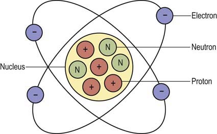
• Coulomb is the standard unit of electric charge, approximately equal to 6.24 × 10¹⁸ electrons.
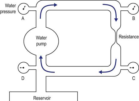
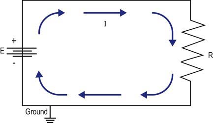
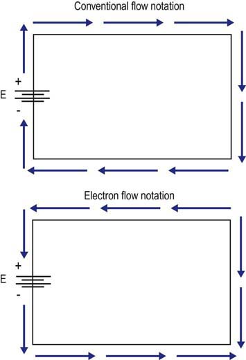
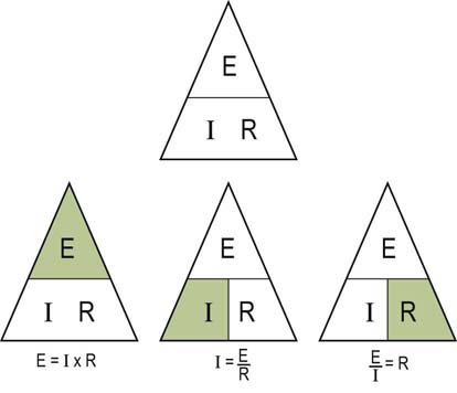
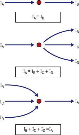
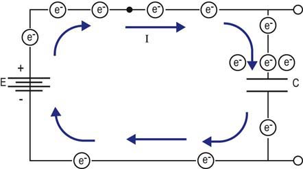
• Current, represented by the symbol I, is the actual flow of electrons. The ampere is a measure of current, designated by the letter A. An ampere is defined as 1 coulomb passing a point in a conductor in 1 second. Current can only flow when a complete circuit exists.
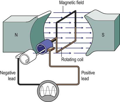
• Voltage is the electromotive force required to make electricity flow through a conductor. This electromotive force results from a fundamental property of magnetism that oppositely charged particles attract each other. Any source with an excess of electrons (negatively charged particle) will be drawn to a source with a lack of electrons (positively charged particle). Voltage is designated by the symbol E. Its unit of measurement is volts, which is designated by the letter V.
• Resistance opposes the flow of electrons. Resistance is designated by the symbol R. The unit of measurement for resistance is Ohms, which is designated by the Greek letter Ω. All materials, even conductors, impede the flow of electrical current to some extent. In general, resistance increases with the length of the conductor and decreases as the cross-section of the conductor increases.


Simple Resistive Circuits
Resistors in Series
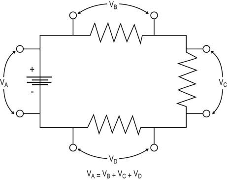
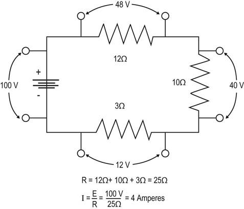
From Ohm’s and Kirchhoff’s laws, one can predict the behavior of simple resistive circuits.
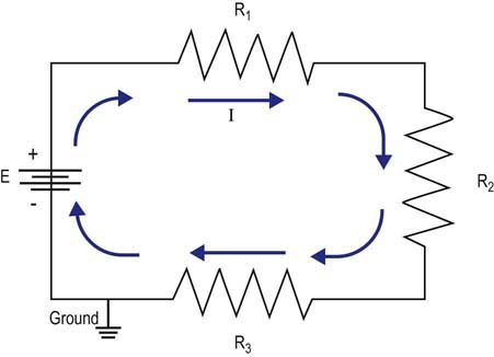
E = VB + VC + VD (Kirchhoff’s voltage law)
E = I × R1 + I × R2 + I × R3 (Ohm’s law)


Capacitance, Inductance, and Reactance
Beyond simple resistive circuits, one needs to move next to the basics of capacitance, inductance, and reactance. Although these concepts are more complicated, they have direct relevance to EDX studies regarding (1) low- and high-frequency filters, and (2) stray leakage currents that potentially pose a risk of electrical injury to patients undergoing EDX studies (see Chapter 40).
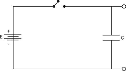
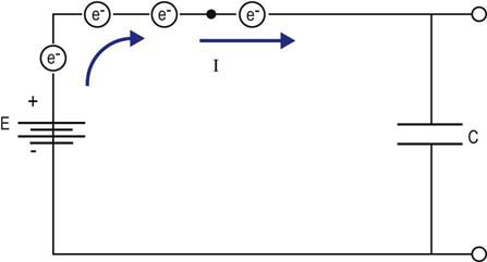
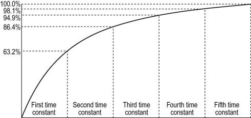
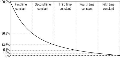
Capacitance

where Q is the charge in coulombs, C is capacitance in Farads, and V is voltage in volts.


e (natural logarithm base) is 2.718281828459045235
R is resistance of the circuit in Ohms


Inductance
e (natural logarithm base) is 2.718281828459045235
R is resistance of the circuit in Ohms


Waveforms, Frequency Analysis, and Filtering

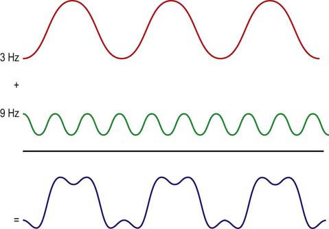
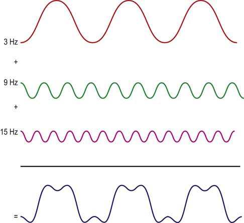
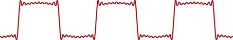
Take the above example of a square wave with a frequency of 3 Hz.
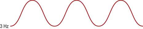
The square wave can first be approximated by a 3 Hz sine wave.

Practical Implications for Electrodiagnostic Studies
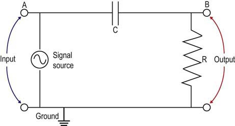
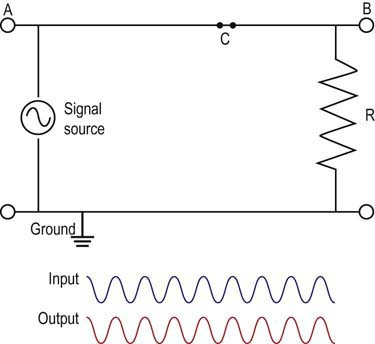
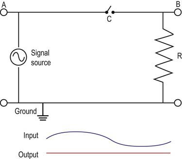
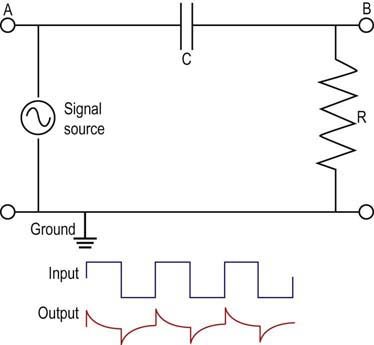
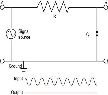
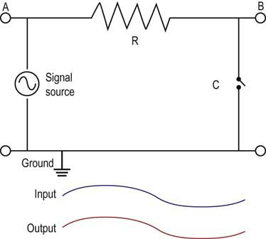
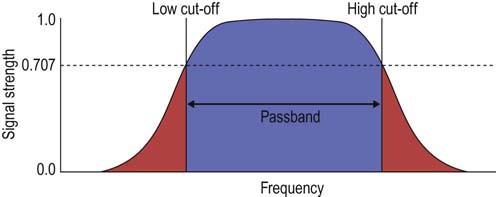
• Filters. Understanding that all waveforms, including those recorded during EDX studies, have their own unique frequency spectrum allows for the use of electronic filters to remove unwanted low- and high-frequency noise while permitting the principal frequencies of the waveform to pass unaffected (i.e., passband). Although filters remove unwanted electrical noise, they also impact the waveform of interest and can alter certain characteristics of the waveform (especially amplitude for high-frequency filters and duration for low-frequency filters).
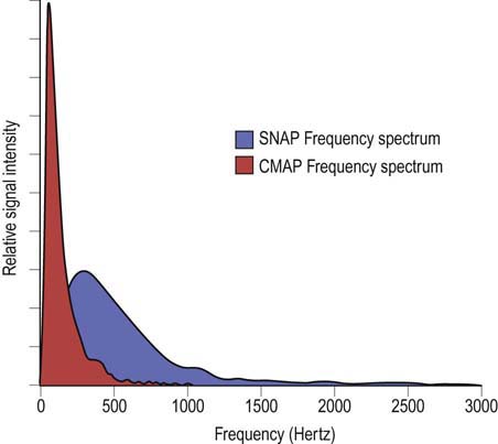
• Tissue acting as a filter: nerve conduction studies. Skin and subcutaneous tissue act as a high-frequency filter. Accordingly, if surface electrodes are not optimally placed directly over a nerve or muscle, much of the waveform’s higher frequencies will be filtered out. Amplitude is predominantly a high-frequency response. SNAPs contain more high frequencies than CMAPs. Thus, if the surface electrodes are not optimally placed, amplitudes on nerve conduction studies will be reduced, more so for SNAPs than for CMAPs. If a patient has limb edema, then even if the surface electrodes are optimally placed, the increased tissue and edema between the nerve or muscle and the recording electrode will result in an artificially low amplitude.
• Tissue acting as a filter: needle EMG. During the needle EMG examination, tissue between the motor unit action potentials and the needle electrode also acts as a high-frequency filter. Again, as amplitude is predominantly a high-frequency response, MUAP amplitude can be markedly influenced by the distance between the needle and the motor unit. During needle EMG, the proper location to analyze an MUAP is reached when the major spike (i.e., the highest frequency component of the MUAP) is very short, less than 500 µs. This ensures that the needle is very close to the motor unit. Likewise, this property of tissue acting as a filter also explains why duration is a much better determinate of motor unit size than is amplitude. Duration is predominantly a low-frequency function. Thus, tissue, which acts as a high-frequency (low-pass) filter, allows the low-frequency components from distant muscle fibers of the same motor unit to be recorded.
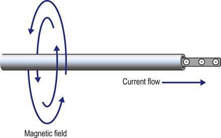
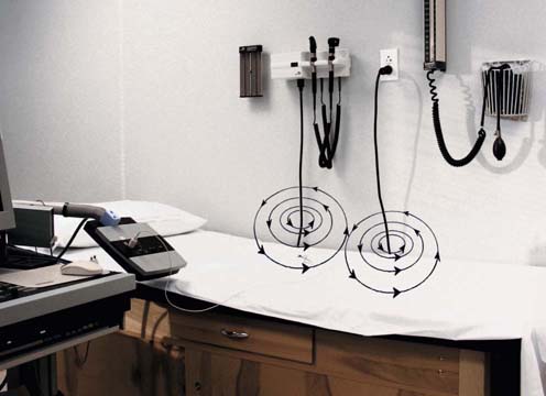
• Inductive electrical noise from the environment. How does a nearby radio or coffee maker result in electrical interference during EDX studies? Every power cord contains a 60 Hz AC signal. Around that power cord is a continuously expanding and collapsing magnetic field. If a conductor (e.g., a recording electrode) is near that magnetic field, an inductive voltage can be generated on that lead, which then can be amplified, often saturating the amplifier and obscuring the signal of interest.
• The stimulator cable and the recording electrodes should not cross or be near each other. When the stimulator is discharged, a brief current flows through the stimulator, creating an expanding and then collapsing magnetic field around the stimulator cable. If the recording electrodes or their leads are near that field (especially if the cables are crossed and touching), an inductive voltage can easily be generated in the recording leads, resulting in a large stimulus artifact.
• Importance of eliminating electrode impedance mismatch. Despite one’s best efforts, there will always be some electrical noise in every EMG laboratory, usually 60 Hz AC from nearby electrical equipment. However, if the impedances (which include resistance, capacitive reactance, and inductive reactance) of the active and reference electrodes are identical, then any current resulting from electrical noise contaminating the recording electrodes will create the same extraneous voltage on each lead (from Ohm’s law: Voltage = CurrentNoise × Impedance). Because all signals are amplified by way of a differential amplifier, the extraneous voltage will be canceled out. Several important techniques help ensure that the recording electrodes have the same impedance, among them, the use of a coaxial cable, good skin preparation, and an ample amount of conductive paste between each electrode and the skin.
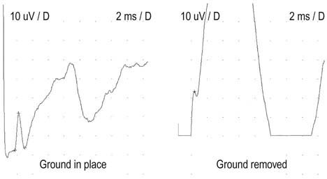
• Importance of the ground electrode. One might assume at first glance that there is no difference between the reference and the ground lead, both being at electrical zero. However, all voltages are relative potentials, determined by the difference between two points in a circuit. Thus, one can measure a potential of 10 V between a point on a circuit that is 10 V higher than the ground (which is at electrical zero). However, 10 V also can be measured in a circuit between a point that is 20 V above ground and another point that is 10 V above ground. Thus, in most electronic applications, there is usually a potential difference (i.e., a voltage) between the neutral or reference electrode, and the ground electrode.
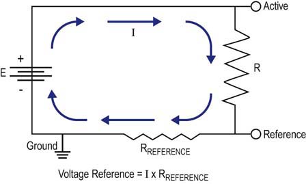
Whenever a waveform is recorded, current flows from the active to the reference lead. Even though the reference electrode is a conductor, there is a small amount of resistance in all materials, including conductors. Thus, a small voltage will be present on the reference lead, as determined by Ohm’s law (E = I × RReference). Accordingly, the ground potential is actually at a lower potential than the reference electrode. If a stray current develops on the patient, the ground allows a safe pathway to dissipate the current, thereby protecting the patient from possible electrical injury (see Chapter 40). In addition, because the ground is at a lower potential than the reference electrode, any stray current will be preferentially shunted to the ground electrode rather than the reference electrode (electricity follows the path of least resistance). Thus, the electrical noise will not contaminate the reference electrode and obscure the potential of interest.
• Leakage currents: stray capacitance and inductance. Although EMG machines are designed to minimize leakage currents, there will always be some leakage current on the machine chassis from stray capacitance and inductance. This is because any circuitry with ACs containing capacitors will have expanding and collapsing electrical fields. Likewise, any circuitry with ACs will have expanding and collapsing magnetic fields. If any part of the machine chassis is metal (i.e., a conductor) and near enough to electrical or magnetic fields from internal circuitry, stray capacitive or inductive currents potentially can be produced. These small leakage currents pose a potential electrical risk to certain vulnerable patient groups (see Chapter 40). With preventative maintenance of the machinery and by closely following specific protocols these possible hazards can be eliminated (see Chapter 40).