[level-membership-for-neurosurgery-category]
CHAPTER 291 Basic Principles of Spinal Internal Fixation
Passive spinal stability is provided by the facet joints, intervertebral disks, and numerous ligaments. Because of the many stabilizing structures, identifying the level of instability beyond which the passive stability requires internal fixation is challenging. Several authors have proposed systems for grading instability, but perhaps the best known is Denis’ three-column theory,1 devised after retrospectively reviewing the radiographic images of 412 thoracolumbar fractures. According to this theory, the anterior column consists of the anterior half of the vertebral body, the anterior half of the annulus fibrosis, and the anterior longitudinal ligament. The middle column consists of the dorsal half of the vertebral body, the dorsal half of the annulus fibrosis, and the posterior longitudinal ligament. The posterior column consists of the pedicles, facets, lamina, pars interarticularis, and posterior ligamentous complex. Denis proposed that an injury that compromises two of the three columns leads to pathologic instability at the affected level (Fig. 291-1).
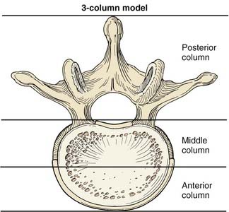
FIGURE 291-1 Illustration of a vertebral body showing the columns of spinal stability as originally described by Denis.1
(Used with permission from Barrow Neurological Institute, Phoenix, AZ.)
Basic Biomechanics
The spine is subjected to numerous forces, typically from gravitational loads, muscular and ligamentous loads, and acceleration and deceleration loads. Forces applied to the spine can be envisioned as vectors (Fig. 291-2). Force vectors applied to the spine can be directed to induce compression, tension, shear, bending, or torsion. A force vector has magnitude and direction in three-dimensional space. Force causes displacement or distortion of an object if it is, respectively, unopposed or opposed.
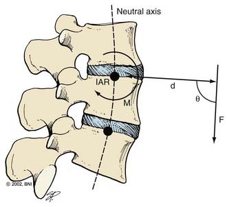
The effect of a force depends on its orientation to a body’s axis of rotation or neutral axis. The axis of rotation is the axis about which a structure bends or rotates. For example, when a door swings open, a line through its hinges would be the axis of rotation. During movement of the spine, the axis of rotation shifts through a range of positions, unlike the fixed axis of rotation of a hinged door. Instantaneous measurement at one time point provides one “snapshot” of the location of the axis of rotation during a particular phase of the movement, or an instantaneous axis of rotation (IAR). In the normal spine, the IAR for a given bending or twisting motion usually remains in or near the disk space because the flexible disk material deforms more easily than the rigid vertebral bodies. The location of the IAR can often be predicted from the curvature of the facet joints and disk.2
The neutral axis is the longitudinal axis along which no axial stresses or strains occur during bending or twisting. For example, when the lumbar spine bends in flexion, the anterior disk fibers compress axially while the posterior fibers stretch axially. The fibers in between, through which the neutral axis runs, neither compress nor stretch (although they may shear anteroposteriorly if the axis of rotation is below the disk space, as is often the case). The neutral axis intersects the IARs of each spinal motion segment along the entire spine at right angles (Fig. 291-2). The neutral axis is a term that applies only to bending or twisting of the spine. No neutral axis exists during pure distraction, compression, or shear because the entire spine is under unidirectional loading in these cases.
where d is any measured distance between the line of action of the force and the location where the moment is assessed, and θ is the angle between the line along which distance is measured and the force vector. The magnitude of the moment increases as the distance from the line of force to the location where moment is measured (i.e., the moment arm) increases.
where Ln is the new length and Li is the initial length. Stress and strain are directly proportional to each other; as stress increases, strain increases. The amount of stress needed to produce a given strain (i.e., the ratio of stress over strain) is Young’s modulus, or the stiffness of a material.
Most biologic materials are much less stiff than the materials used in spinal fixation (Table 291-1). The modulus of elasticity of a material describes the stress (force per unit of cross-sectional area) per unit of strain (linear deformation per unit of length) in the elastic region. A higher modulus of elasticity implies a stiffer, or more rigid, implant. However, most biologic materials have both viscous and elastic (viscoelastic) properties, whereas implant materials act primarily as elastic elements. The viscous properties present in the spine permit long-term and rate-dependent responses to loads. With the application of stress to a material with viscoelastic properties, elastic strain is apparent immediately, whereas viscous strain becomes apparent over time as the stress in the system declines exponentially. Strains applied to viscoelastic materials at a high rate, such as during a car accident, cause higher stresses in the tissues resisting the strains than the same strains applied at a lower rate, such as during a lifting accident.
| MATERIAL | YIELD STRENGTH (MPa) | MODULUS OF ELASTICITY (MPa) |
|---|---|---|
| Bone | ||
| Cancellous bone | 2 | 90 |
| Lumbar vertebra | 5 | 160 |
| Cervical vertebra | 10 | 230 |
| Cortical bone | 150 | 12,000 |
| Biomaterials | ||
| Polyethylene (UHMWPE) | 20 | 870 |
| Polymethylmethacrylate | 100 | 2,400 |
| Polyetheretherketone (PEEK) | 140 | 3,400 |
| Ti (Grade 4) | 560 | 104,000 |
| Ti6Al4V | 825 | 114,000 |
| Stainless steel (316) | 205 | 193,000 |
| Cobalt chromium | 620 | 233,000 |
UHMWPE, ultra-high-molecular-weight polyethylene.
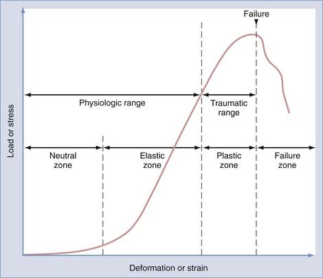
Physiologic range of motion is the range through which the spine can move without injury and is dictated by the viscoelastic properties of the spinal motion segment (Fig. 291-3). For small deformations, ligaments and other soft tissues are lax; consequently, the stiffness of the system is low. The portion of the range of motion at which little stress is required to produce large deformations of the spinal motion segment is known as the neutral zone. In contrast, in the elastic zone, exceedingly larger forces are required to produce small incremental changes in deformation. In the elastic zone, the ligaments and other soft tissues are stretching, whereas in the neutral zone, they have not yet begun to stretch.3
Physiologic Spinal Loading
where w is the weight of the body above the spinal motion segment, Lg is the distance from the IAR to the center of gravity, and Ld is the distance from the IAR to the dorsal muscles of the spine. Because Lg is always larger than Ld when standing upright, the actual compression experienced by the spinal motion segment is often two to four times that due to simple gravitational loading. When the orientation of the IAR or center of gravity changes, the load that must be exerted by the posterior muscles changes. When holding an object in one’s arms in front of the torso, for example, the center of gravity is displaced anteriorly from the IAR, and the compressive load increases. This point is important because when the posterior muscle tissues are compromised by surgery or trauma—or when the IAR is shifted by surgery, degeneration, or trauma—spinal biomechanics change significantly. Another observation from this analysis is that an obese patient, whose center of gravity is shifted farther anterior, will have more difficulty coping with compromised dorsal musculature than a fit patient.
Basics of Spinal Instrumentation
Screws
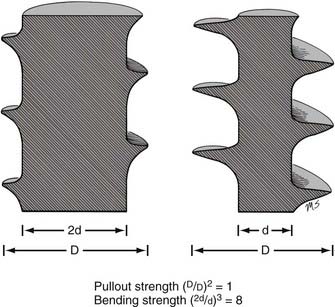
The mechanical bending strength of a screw is a function of the diameter of the shaft. Changes in the minor diameter significantly increase or decrease the bending strength of a screw.4 A twofold change in the minor diameter increases the screw’s bending strength eightfold because the highest stress, S, applied to a screw during three-point bending is a function of the equation
where F is the force applied at either end of the screw, L is the length of the screw, and d is its minor diameter. Often, the bending moment or shear force at the proximal aspect of the screw shaft is large because of the orientation of forces at the screw head-plate junction, which can mimic the claw of a hammer prying the head of a nail. Because the transition from the threaded to the nonthreaded portion of the shaft is accompanied by an abrupt increase in the minor diameter of the screw, this area can function as the weak point in the screw and is often the site of screw failure.5,6
The pullout strength of a screw depends on numerous variables. Most important are the screw-bone interface and the quality of the bone.4 Cortical bone provides a more secure purchase than does trabecular bone. Diseased osteopenic bone provides poor structural support. During screw insertion, trauma related to poor drilling techniques or overheating can impair the screw’s purchase or lead to the pathologic resorption of bone around the screw.7 Rescue screws used in cervical plating systems and thoracolumbar pedicle screws have a wider diameter to recover purchase in a stripped or enlarged screw hole. The pullout strength of a screw depends on the depth at which the screw is placed and the screw’s major diameter.8 Note that unlike a screw’s bending strength, the pullout strength is affected little by the screw’s minor diameter (except when the dimensions of the major and minor diameters are too close to create bite, or when the bone surrounding the hole is nonuniform). Hence, a twofold increase in minor diameter that causes an eightfold increase in bending strength should have little or no effect on pullout strength (Fig. 291-4).
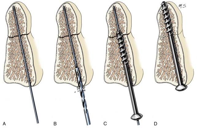
Lag screws place bone fragments under compression (Fig. 291-5). The shaft of a lag screw has both threaded and nonthreaded portions. The threaded portion of the shaft, which is the distal portion, is used to engage a distal bone fragment. As the screw is tightened, the distal fragment is compressed toward the proximal fragment as long as the threaded portion of the shaft does not cross the fracture line. A lag effect in a fully threaded screw also can be obtained by drilling the proximal portion of the screw hole to the screw’s major diameter so that the screw obtains no purchase proximally. A lag effect can also be obtained by using a screw with a threaded shaft divided into two portions based on a difference in the pitch and depth of the thread. This difference causes the distal portion of the screw to advance more rapidly than the proximal portion, which consequently compresses the bone fragments.
Cannulated screws have a hollow shaft that allows the screw to be placed over a thin surgical guidewire. These screws are used when precise placement is needed, as in transarticular screw placement. The hollow aspect of the screw’s shaft slightly reduces its bending strength but does not affect its pullout strength.9 Because the outer region of metal in a screw shaft is more important in resisting bending than the core, substantial bending strength can still be maintained with cannulation. For example, a 2.5-mm minor diameter screw with a 1.5-mm diameter cannula is theoretically 87% as strong in bending as a solid 2.5-mm diameter screw; a 3-mm minor diameter screw with a 1.5-mm diameter cannula is theoretically 94% as strong in bending as its solid counterpart.
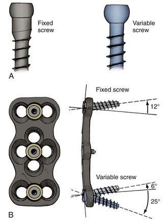
Screws also differ based on their relationship to the overlying plate or rod (Fig. 291-6). When the screw head’s interface with the overlying apparatus is rigid, the system is described as constrained. When the screw head’s interface is nonrigid, the system is described as nonconstrained. The design of the hardware determines whether a constrained screw can have a variable trajectory during placement. For example, in most cervical plating systems, screws placed with a fixed trajectory are, by definition, constrained screws because of how the screw head–plate interface is designed. In contrast, in most pedicle screw systems, the trajectory of the screw does not affect the screw’s ability to rigidly fixate to the overlying rod, so these screws can be described as variable-trajectory screws in a constrained system.
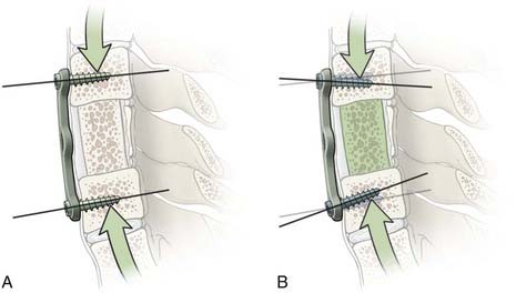
Constrained screws provide more rigid immobilization and are generally more desirable when treating traumatic instability. Nonconstrained screws are desirable when treating degenerative instability because they allow settling at the screw-plate interface while the adjacent fusion mass subsides over time. Nonconstrained constructs have helped solve the problem of stress shielding of the bone graft and thus have led to increased fusion rates in patients with degenerative conditions.10 Although materials used for spinal fixation are usually stiffer than any of the surrounding biologic materials, some of the more recent fixation devices use materials with mechanical properties better matching the stiffness of bone, such as PEEK (polyetheretherketone; see Table 291-1). Such material selection mitigates stress shielding, a phenomenon in which the majority of the natural loading of the spine is borne by the hardware instead of the bone. Wolff’s Law states that bone will adapt to the loads under which it is placed. Therefore, if the hardware bears the majority of the load, the adjacent bone will atrophy and disappear, possibly leading to an unstable nonunion. A more favorable situation is where the fusion hardware and bone graft for fusion participate in load sharing, in which Wolff’s Law leads to formation of new bone across the graft and diminishing loads across the hardware over time (Fig. 291-7).
Some basic considerations regarding screw fixation can be employed in optimizing screw constructs. Using the largest diameter screw possible reduces the stress applied to the screw.11 Setting screws deeply into the bone (i.e., pedicle or vertebral body) lowers the profile of the hardware and decreases the moment arm at the screw head, lowering the susceptibility of the proximal shaft to failure from gravitational loads.7 Placing longer screws deeper into the bone also reduces the propensity for screw pullout.12 When the cancellous bone-screw interface is poor, a bicortical screw purchase may be desirable to increase the pullout strength of the screw.
Rods and Plates
Manipulating rods and plates before their application can affect their integrity. Stress risers result from contouring rods and plates, so excessive contouring should be avoided. Notching, which also occurs from contouring techniques, results when the structural integrity of the rod or plate is compromised. Titanium is especially susceptible to both stress risers and notching-related phenomena. A notch as small as 1% can reduce the fatigue resistance of 316L stainless steel wire by 63%.13 Notching also increases the corrosion rate of the implant.
Certain biomechanical considerations apply regarding the geometry of constructs that employ rods. Preventing rods from being placed in a parallel orientation can reduce complications related to rotational or torsional strain (the parallelogram effect).14,15 Placing rods in a convergent orientation or using transverse connectors can reduce the propensity for failure because of this problem. In a rod construct for correction of deformity, the magnitude of the moment generated at the fulcrum of the construct is proportional to the length of the construct.16 Therefore, there is a mechanical advantage to using longer constructs for reduction.
Wires
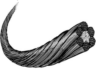
Wires are used in a variety of posterior fixation techniques. Sublaminar wiring and spinous process wiring are some of the oldest techniques used in posterior spinal fixation. There are single-stranded wires, twisted wires, and braided cables. Braided cables (Fig. 291-8) tend to be the strongest and tend to distribute tension most evenly.17 Braided cable is available in both titanium and stainless steel alloys, with stainless steel cables generally providing better strength and resistance to fatigue.17 Although cables and wires are commonly used, there is growing evidence that screw systems are more rigid and less susceptible to loosening than are wired alternatives.18
Fixation Categories
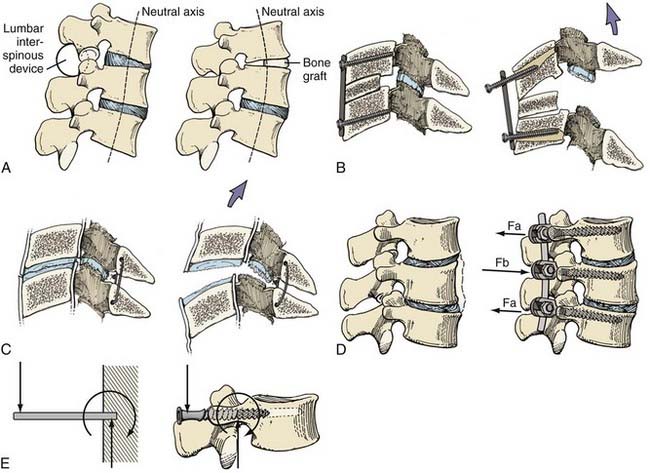
There are four basic categories of fixation techniques: simple distraction, tension band, three-point bending, and cantilever (Fig. 291-9). Simple distraction refers to a fixation construct in which a purely distractive force is applied, usually by a wedge. Simple distraction affects sagittal balance differently depending on whether it is applied anterior or posterior to the spine’s neutral axis. A tension band refers to hardware that acts as a tether that tightens against bending of the spine. Three-point bending usually applies to a rod construct and refers to bending caused by the rod’s central fulcrum and two opposing termini; such constructs are often used to apply corrective moments to rectify kyphosis or scoliosis. Cantilever fixation refers to a screw embedded as a cantilever into bone with forces largely orthogonal to the screw.
Practical Applications of the Biomechanics of Spinal Fixation
White and Panjabi19 cited four basic indications for spinal stabilization: (1) restoration of stability when stability is compromised by trauma or degenerative changes; (2) maintenance of alignment after alignment correction; (3) prevention of further alignment deformities; and (4) alleviation of pain related to instability or pathologic movement. Fixation techniques are used to provide the spine with temporary rigid or semirigid fixation until osseous fusion can occur. The basis of almost all internal fixation techniques is successful bone fusion. With continued repetitive loading in the absence of osseous fusion, all fixation methods eventually fatigue and fail. In fact, some surgeons advocate—and certain clinical situations require—the eventual removal of nonbiologic hardware after osseous fusion has developed.
Cervical Spine
Odontoid fractures are treated with either odontoid screw (see Fig. 291-5) or C1-2 posterior fusion techniques (Figs. 291-10 and 291-11). Odontoid screw fixation techniques use a lag screw, which stabilizes the fracture temporarily and approximates fragments until osseous fusion develops. When odontoid screw techniques cannot be applied because of a transverse ligament rupture20–22 or an ill-suited fracture pattern, a C1-2 fusion is performed. Traditional C1-2 fusion techniques use a posterior wiring technique (tension band) and an interspinous bone strut (simple distraction). The presence of an interspinous bone strut counteracts the tendency for the posterior wiring technique to fail from narrowing of the interanchor distance. The interspinous bone strut also permits osseous fusion. The Gallie and Sonntag fusion techniques are examples (see Fig. 291-10). The additional application of transarticular screws helps form a rigid construct that promotes osseous fusion by counteracting the system’s tendency to fail because of its susceptibility to rotational stresses (see Fig. 291-11). Either transarticular screws or a halo vest is required to stabilize C1-2 adequately for most types of injuries.23 Biomechanical comparisons have confirmed that transarticular screws form the most rigid constructs.24,25
Ventral cervical bone grafts are used to treat both trauma and degenerative conditions. A ventral bone graft functions as a simple distractive force. Ventral plating functions as a fixed or nonfixed cantilever beam system that provides axial load sharing and immobilization to promote fusion.10,26 It also reconstructs the ventral tension band.
Thoracolumbar Spine
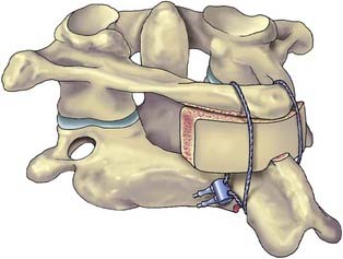
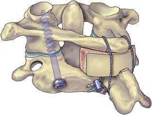
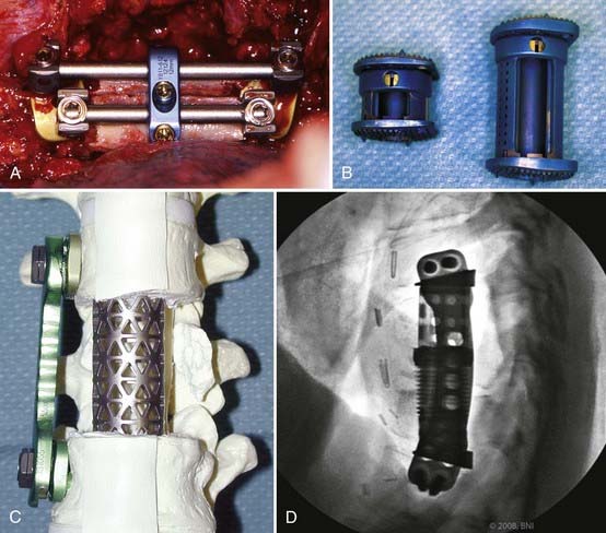
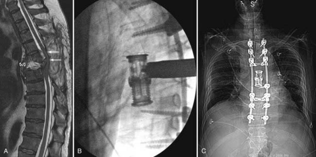
Pedicle screw systems are short segment–short fusion fixed moment arm cantilever beam systems. Alone, they are used to treat glacial instability from acquired or degenerative spondylolisthesis. When used to treat angulation deformities caused by traumatic or osteodegenerative fractures, they usually require the application of a ventral strut (simple distraction) to reduce gravitational load bearing by the hardware. The ventral strut may be a bone graft or a titanium mesh cage when a corpectomy is performed (Fig. 291-12). With continued development and evolution of these anterior expandable cages, the size and shape of graft and end plate covers can be customized for fit. In selected cases, these cages can now even be placed from a posterior trajectory (Fig. 291-13).27–29 When the pathology is confined to the disk space, the ventral strut may be an anterior lumbar interbody fusion device, a posterior lumbar interbody fusion device, or more recently, a laterally placed device (XLIF [Nuvasive, San Diego, CA]). These grafts apply a simple distractive force. When the grafts are applied anteriorly, the surgical approach compromises the anterior tension band (anterior longitudinal ligament). When interbody grafts are applied posteriorly, the surgical approach compromises the facets and the posterior tension band. In the absence of additional hardware such as a fixed moment arm cantilever beam (pedicle screw-rod) system to reconstruct the missing tension band, interbody cages may be unstable constructs. To date, however, no long-term clinical outcomes have been compiled to support or disprove this notion. Newer systems using a lateral approach (XLIF) show promise but also require further long-term studies.
Emerging Treatments
Image Guidance
Image guidance refers to any technique by which medical images are synchronized to coordinates within the operating room via three-dimensional computerized tracking. The use of image guidance improves the accuracy of spinal procedures.30,31 Iso-C fluoroscopy (Siremobil Iso-C3D, Siemens, Medical Solutions, Erlangen, Germany) is a contemporary modality that allows intraoperative three-dimensional imaging in the operating room without the need to reposition the patient and without restricting access to the patient. Multiple fluoroscopic images acquired about an isocentric point in space provide axial tomographic images that can be reconstructed accurately into a three-dimensional volume.32 This modality enables accurate correlation between three-dimensional images and the patient’s anatomy in the operating room and provides navigational support based on updated image data (Fig. 291-14). The Iso-C3D is useful for most cervical spinal procedures either in conjunction with spinal navigation or simply as an intraoperative computed tomography (CT) scan. In the latter case, it can be used to verify the extent of osseous decompression or cervical alignment in three dimensions or to confirm appropriate placement of instrumentation.
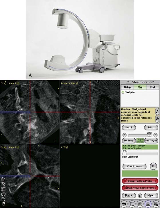
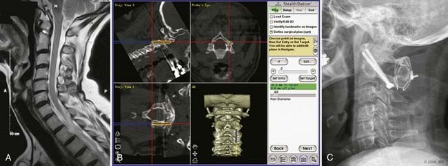
Image guidance improves accuracy of screw placement compared to freehand screw insertion, but it does not eliminate error. Cervical pedicle screws inserted by freehand were associated with an 87% breach rate, but cervical pedicle screws inserted with assistance from image guidance were still associated with a 24% breach rate.33 In our practice, image guidance has been used most often in patients with anomalous anatomy or small bony anatomy, requiring increased precision (Fig. 291-15).
Biologics
The discovery of bone morphogenic proteins (BMPs) by Urist in 196534 has led to an explosion of research aimed at identification and characterization of osteoinductive growth factors. BMPs are members of the transforming growth factor-beta (TGF-β) superfamily that have been proposed for a number of applications in orthopedic surgery.35 Fourteen different BMPs have been reported,36 but only recombinant BMP-2 (rhBMP-2) and BMP-7 (osteogenic protein-1, rhOP-1) have been evaluated in preclinical models. Successful healing in long bone defects and in spinal arthrodesis models in animals has been reported.35,37–39 U.S. Food and Drug Administration (FDA) approval was recently granted for the use of rhBMP-2 to enhance anterior spinal fusion40 and rhOP-1 to supplement posterior spine fusions.41
In making decisions on bone substitutes and enhancers, surgeons must assess the host biologic environment and must ensure that four critical elements are present to promote bone repair: the presence of bioactive factors, responding cells, matrix, and an adequate vascular supply. The body of evidence reporting the efficacy of rhBMP in clinical studies has grown considerably over the past 5 years. Since the first report of BMP-induced osteoinduction in a clinical trial,40 additional studies have reported the superiority of rhBMP to the use of autogenous bone graft.42–46 Future uses of rhBMP may also lead to higher success rates in minimally invasive procedures and lessen surgical exposures and operative time.
However, despite excellent clinical results, many concerns still exist for the routine use of recombinant growth factors. Although safety has been demonstrated in initial trials, long-term effects have not fully been elucidated.47–49 A number of complications, including local soft tissue edema and bone resorption, have been associated with its use in both the cervical and lumbar spine.47,50,51 Furthermore, the cost of rhBMP currently precludes its routine use in spine arthrodesis, and further study will be necessary to delineate the clear indications in which BMPs should be used. At the current time, the costs and complications associated with the use of recombinant proteins do not justify its routine use. Individual patient characteristics that increase the risk of pseudarthrosis such as smoking, osteoporosis, multilevel and revision surgeries, and previous graft site harvest may justify the additional costs of BMPs as a bone graft substitute during surgery.52 Further studies delineating the indications for BMP use in spine surgery are warranted.
Polymer Biomaterials
The degree of stiffness of a pedicle screw-rod construct is extremely supraphysiologic compared with the modulus of elasticity of an uninstrumented mature posterolateral fusion.53–55 This difference is even more pronounced when compared with the native spine. Nonmalleable constructs of stainless steel or titanium are far more rigid than needed to augment fusion and there is presumably an optimum degree of stiffness that would promote fusion while lowering the rate and incidence of adjacent level disease.
Recently, a new generation of spinal implants made of polyaryletherketone (PAEK) has been developed. Commercialized for industry in the 1980s, PAEK is a relatively new family of high-temperature thermoplastic polymers, consisting of an aromatic backbone molecular chain, interconnected by ketone and ether functional groups.56 Two PAEK polymers in clinical use include polyetheretherketone (PEEK) and polyetherketoneetherketoneketone (PEKEKK).57 PEEK polymer has a modulus of elasticity between that of cortical and cancellous bone, with load characteristics more consistent with the native environment (see Table 291-1). PAEK biomaterials were first introduced as spinal cages in the 1990s by Caromed (Cleveland; now DePuy Spine, Raynham, MA.) A prospective, multicenter investigational device exemption study was initiated for the FDA in 1991.58 Altogether, 221 patients received a carbon-reinforced PEKEKK cage with posterior pedicle screw fixation. Successful fusion was reported in 176 of 178 (98.9%) patients with a 2-year follow-up. Longer term follow-up has also been reported.59 The clinical and commercial success of this medical device lay the foundation of the current widespread use of PEEK in spine implants.
PEEK rods are semirigid alternatives to their nonmalleable stainless steel or titanium counterparts.60 These rods allow some motion but resist marked flexion, extension, axial loading, and lateral rotation. Laboratory testing has demonstrated their ability to substantially reduce stress-shielding characteristics and to reduce hypermobility at adjacent levels compared with titanium screw and rod constructs.61,62 It is believed that more compliant materials such as nitinol or PEEK can maintain or restore the load-sharing characteristics to the level of the intact spine with less stress shielding. PEEK is a radiolucent material that does not interfere with plain x-ray films or CT scans, which are the “gold standard” for evaluating the status of a fusion. Numerous studies have remarked on the radiolucent qualities of the implants.58,63 The compatibility of PAEK polymers with clinical diagnostic imaging has been a major impetus for the adoption of this polymer family for spinal applications. Additional biomechanical and clinical data will help define further uses of this polymer family in novel spinal applications.
Dynamic Systems
Single-level cervical fusion has not been shown to decrease the overall motion of the cervical spine, but the kinematics at a level adjacent to fusion is altered.64,65 In untreated levels adjacent to fusion, increases in motion—with increased shear strains and elevated intradiscal pressures—have been reported.66–68 Investigators have postulated that these changes may lead to an increased risk of adjacent-segment degeneration.69–71
Dynamic neutralization systems aim to provide nonrigid stabilizing forces to overcome the inherent disadvantages of a solid fusion and adjacent level disease.72–74 Theoretically, a rigid metallic three-level fixation system for lumbar fusion creates a lever arm that results in increased moment at the junction of the fusion mass with the normal rostral adjacent levels. However, instrumentation systems using rods with a reduced modulus of elasticity (e.g., PEEK; see Table 291-1) that more closely resembles bone or that uses a gradient in the modulus of elasticity in the more rostral fixated segments are under development and may reduce the incidence of transition syndrome.
Total disk replacement (TDR) is another method of preserving function to reduce adjacent level disease. A TDR is a device that is placed into the intervertebral disk space after the disk is removed instead of a bone graft with the goal of retaining as much normal motion as possible while stabilizing the motion segment. The theoretical advantages are to reduce the incidence of adjacent segment degeneration while maintaining normal neck motion, eliminating complications at the bone graft donor site (including disease transmission from donor bone graft), and mobilizing the patient earlier without the need for bracing. Cervical disk arthroplasty has the potential of maintaining the anatomic height of the disk space, normal segmental lordosis, and physiologic motion patterns after surgery. These characteristics may reduce or delay the onset of degenerative disk disease at adjacent cervical spinal motion segments after anterior cervical decompressive surgery.75,76
There are numerous investigational TDR devices for both cervical and lumbar disease. There are three lumbar TDRs approved by the FDA: Charité (DePuy Spine), ProDisc (Synthes), and Maverick (Medtronic). The initial randomized FDA investigational study on the lumbar Charité device was promising.77 Later studies, however, have reported high complication rates with this device,78–80 casting doubt on the long-term ability of any lumbar TDR to withstand the high stresses of the lumbar region.
Cervical TDRs appear to be more promising. Presently, two cervical TDRs are FDA-approved in the United States: the PRESTIGE (Medtronic, Minneapolis) and the ProDisc-C (Synthes, West Chester, PA). In a large prospective randomized controlled clinical trial, compelling data that support the use of cervical total disk arthroplasty as a substitute for bone fusion after anterior cervical diskectomy have been demonstrated with the Prestige ST Cervical Disc System (Medtronic Sofamor Danek, Minneapolis)76,81 and Bryan Disc (Medtronics).82 These preliminary results show that these systems had maintained physiologic segmental motion 24 months after implantation and were associated with successful neurological outcomes. The Prestige trial also showed improved clinical outcomes, reduced return to work times, and a reduced rate of secondary surgeries when compared with anterior cervical diskectomy and fusion.76,81
Bartolomei JC, Theodore N, Sonntag VK. Adjacent level degeneration after anterior cervical fusion: a clinical review. Neurosurg Clin N Am. 2005;16:575-587.
Benzel EC. Biomechanics of Spinal Stabilization: Principles and Practice. New York: McGraw-Hill; 1995.
Blumenthal S, McAfee PC, Guyer RD, et al. A prospective, randomized, multicenter Food and Drug Administration investigational device exemptions study of lumbar total disc replacement with the CHARITE artificial disc versus lumbar fusion: part I: evaluation of clinical outcomes. Spine. 2005;30:1565-1575.
Boden SD, Zdeblick TA, Sandhu HS, et al. The use of rhBMP-2 in interbody fusion cages. Definitive evidence of osteoinduction in humans: a preliminary report. Spine. 2000;25:376-381.
Chang S, Kakarla K, Maughan P, et al. Four-Level anterior cervical discectomy and fusion with plate fixation: radiographic and clinical results. Neurosurgery. 2010;66:639-697.
Cheng H, Jiang W, Phillips FM, et al. Osteogenic activity of the fourteen types of human bone morphogenetic proteins (BMPs). J Bone Joint Surg Am. 2003;85-A:1544-1552.
Dickman CA, Greene KA, Sonntag VK. Injuries involving the transverse atlantal ligament: classification and treatment guidelines based upon experience with 39 injuries. Neurosurgery. 1996;38:44-50.
Dickman CA, Mamourian A, Sonntag VK, et al. Magnetic resonance imaging of the transverse atlantal ligament for the evaluation of atlantoaxial instability. J Neurosurg. 1991;75:221-227.
Dickman CA, Papadopoulos SM, Crawford NR, et al. Comparative mechanical properties of spinal cable and wire fixation systems. Spine. 1997;22:596-604. 1999;90:84-90
Holly LT, Foley KT. Intraoperative spinal navigation. Spine. 2003;28:S54-S61.
Hott JS, Lynch JJ, Chamberlain RH, et al. Biomechanical comparison of C1-2 posterior fixation techniques. J Neurosurg Spine. 2005;2:175-181.
Hott JS, Papadopoulos SM, Theodore N, et al. Intraoperative Iso-C C-arm navigation in cervical spinal surgery: review of the first 52 cases. Spine. 2004;29:2856-2860.
Kurtz SM, Devine JN. PEEK biomaterials in trauma, orthopedic, and spinal implants. Biomaterials. 2007;28:4845-4869.
Ludwig SC, Kowalski JM, Edwards CC, et al. Cervical pedicle screws: comparative accuracy of two insertion techniques. Spine. 2000;25:2675-2681.
Mummaneni PV, Burkus JK, Haid RW, et al. Clinical and radiographic analysis of cervical disc arthroplasty compared with allograft fusion: a randomized controlled clinical trial. J Neurosurg Spine. 2007;6:198-209.
Mummaneni PV, Haid RW. The future in the care of the cervical spine: interbody fusion and arthroplasty. Invited submission from the Joint Section Meeting on Disorders of the Spine and Peripheral Nerves, March 2004. J Neurosurg Spine. 2004;1:155-159.
Panjabi MM. The stabilizing system of the spine. Part II. Neutral zone and instability hypothesis. J Spinal Disord. 1992;5:390-396.
Vaccaro AR, Anderson DG, Patel T, et al. Comparison of OP-1 Putty (rhBMP- 7) to iliac crest autograft for posterolateral lumbar arthrodesis: a minimum 2-year follow-up pilot study. Spine. 2005;30:2709-2716.
Weiser MW, Luevano CA, Goel VK, et al. Spinal implant attributes: distraction, compression, and three-point bending. In: Benzel EC, editor. Spine Surgery. Philadelphia: Churchill Livingstone; 1999:979-990.
White AAIII, Panjabi MM. Clinical Biomechanics of the Spine. Philadelphia: Lippincott-Raven; 1990.
1 Denis F. The three column spine and its significance in the classification of acute thoracolumbar spinal injuries. Spine. 1983;8:817-831.
2 Penning L, Wilmink JT. Rotation of the cervical spine. A CT study in normal subjects. Spine. 1987;12:732-738.
3 Panjabi MM. The stabilizing system of the spine. Part II. Neutral zone and instability hypothesis. J Spinal Disord. 1992;5:390-396.
4 Benzel EC. Biomechanics of Spinal Stabilization: Principles and Practice. New York: McGraw-Hill; 1995.
5 Cunningham BW, Sefter JC, Shono Y, et al. Static and cyclical biomechanical analysis of pedicle screw spinal constructs. Spine. 1993;18:1677-1688.
6 Yoganandan N, Larson SJ, Pintar F, et al. Biomechanics of lumbar pedicle screw/plate fixation in trauma. Neurosurgery. 1990;27:873-880.
7 Bennett GL. Materials and materials testing. In: Benzel EC, editor. Neurosurgical Topics: Spinal Instrumentation. Park Ridge, IL: American Association of Neurological Surgeons; 1994:31-46.
8 Skinner R, Maybee J, Transfeldt E, et al. Experimental pullout testing and comparison of variables in transpedicular screw fixation. A biomechanical study. Spine. 1990;15:195-201.
9 Collinge CA, Stern S, Cordes S, et al. Mechanical properties of small fragment screws. Clin Orthop. 2000;373:277-284.
10 Chang S, Kakarla K, Maughan P, et al. Four-level anterior cervical discectomy and fusion with plate fixation: radiographic and clinical results. Neurosurgery. 2010;66:639-647.
11 Misenhimer GR, Peek RD, Wiltse LL, et al. Anatomic analysis of pedicle cortical and cancellous diameter as related to screw size. Spine. 1989;14:367-372.
12 Krag MH, Beynnon BD, Pope MH, et al. Depth of insertion of transpedicular vertebral screws into human vertebrae: effect upon screw-vertebra interface strength. J Spinal Disord. 1988;1:287-294.
13 Weiser MW, Luevano CA, Goel VK, et al. Spinal implant attributes: distraction, compression, and three-point bending. In: Benzel EC, editor. Spine Surgery. Philadelphia: Churchill Livingstone; 1999:979-990.
14 Gaines RWJr, Carson WL, Satterlee CC, et al. Experimental evaluation of seven different spinal fracture internal fixation devices using nonfailure stability testing. The load-sharing and unstable-mechanism concepts. Spine. 1991;16:902-909.
15 Carson WL, Duffield RC, Arendt M, et al. Internal forces and moments in transpedicular spine instrumentation. The effect of pedicle screw angle and transfixation—the 4R-4bar linkage concept. Spine. 1990;15:893-901.
16 Duffield RC, Carson WL, Chen LY, et al. Longitudinal element size effect on load sharing, internal loads, and fatigue life of tri-level spinal implant constructs. Spine. 1993;18:1695-1703.
17 Dickman CA, Papadopoulos SM, Crawford NR, et al. Comparative mechanical properties of spinal cable and wire fixation systems. Spine. 1997;22:596-604.
18 Hurlbert RJ, Crawford NR, Choi WG, et al. A biomechanical evaluation of occipitocervical instrumentation: screw compared with wire fixation. J Neurosurg. 1999;90:84-90.
19 White AAIII, Panjabi MM. Clinical Biomechanics of the Spine. Philadelphia: Lippincott-Raven; 1990.
20 Dickman CA, Greene KA, Sonntag VK. Injuries involving the transverse atlantal ligament: classification and treatment guidelines based upon experience with 39 injuries. Neurosurgery. 1996;38:44-50.
21 Dickman CA, Mamourian A, Sonntag VK, et al. Magnetic resonance imaging of the transverse atlantal ligament for the evaluation of atlantoaxial instability. J Neurosurg. 1991;75:221-227.
22 Greene KA, Dickman CA, Marciano FF, et al. Transverse atlantal ligament disruption associated with odontoid fractures. Spine. 1994;19:2307-2314.
23 Crawford NR, Hurlbert RJ, Choi WG, et al. Differential biomechanical effects of injury and wiring at C1-C2. Spine. 1999;24:1894-1902.
24 Bambakidis NC, Feiz-Erfan I, Horn EM, et al. Biomechanical comparison of occipitoatlantal screw fixation techniques. J Neurosurg Spine. 2008;8:143-152.
25 Hott JS, Lynch JJ, Chamberlain RH, et al. Biomechanical comparison of C1-2 posterior fixation techniques. J Neurosurg Spine. 2005;2:175-181.
26 Galler RM, Dogan S, Fifield MS, et al. Biomechanical comparison of instrumented and uninstrumented multilevel cervical discectomy versus corpectomy. Spine. 2007;32:1220-1226.
27 Crocker M, Chitnavis B. Total thoracic vertebrectomy with anterior and posterior column reconstruction via single posterior approach. Br J Neurosurg. 2007;21:28-31.
28 Sciubba DM, Gallia GL, McGirt MJ, et al. Thoracic kyphotic deformity reduction with a distractible titanium cage via an entirely posterior approach. Neurosurgery. 2007;60(4 suppl 2):223-230.
29 Shen FH, Marks I, Shaffrey C, et al. The use of an expandable cage for corpectomy reconstruction of vertebral body tumors through a posterior extracavitary approach: a multicenter consecutive case series of prospectively followed patients. Spine J. 2008;8:329-339.
30 Holly LT, Foley KT. Intraoperative spinal navigation. Spine. 2003;28:S54-S61.
31 Hott JS, Papadopoulos SM, Theodore N, et al. Intraoperative Iso-C C-arm navigation in cervical spinal surgery: review of the first 52 cases. Spine. 2004;29:2856-2860.
32 Euler E, Wirth S, Pfeifer J. 3-D imaging with an isocentric mobile C-arm. Electromedica. 2000;68:122-126.
33 Ludwig SC, Kowalski JM, Edwards CC, et al. Cervical pedicle screws: comparative accuracy of two insertion techniques. Spine. 2000;25:2675-2681.
34 Urist MR. Bone: formation by autoinduction. Science. 1965;150:893-899.
35 Zabka AG, Pluhar GE, Edwards RBIII, et al. Histomorphometric description of allograft bone remodeling and union in a canine segmental femoral defect model: a comparison of rhBMP-2, cancellous bone graft, and absorbable collagen sponge. J Orthop Res. 2001;19:318-327.
36 Cheng H, Jiang W, Phillips FM, et al. Osteogenic activity of the fourteen types of human bone morphogenetic proteins (BMPs). J Bone Joint Surg Am. 2003;85:1544-1552.
37 Cook SD, Dalton JE, Tan EH, et al. In vivo evaluation of recombinant human osteogenic protein (rhOP-1) implants as a bone graft substitute for spinal fusions. Spine. 1994;19:1655-1663.
38 Cook SD, Wolfe MW, Salkeld SL, et al. Effect of recombinant human osteogenic protein-1 on healing of segmental defects in non-human primates. J Bone Joint Surg Am. 1994;77:734-750.
39 Yasko AW, Lane JM, Fellinger EJ, et al. The healing of segmental bone defects, induced by recombinant human bone morphogenetic protein (rhBMP-2). A radiographic, histological, and biomechanical study in rats. J Bone Joint Surg Am. 1992;74:659-670.
40 Boden SD, Zdeblick TA, Sandhu HS, et al. The use of rhBMP-2 in interbody fusion cages. Definitive evidence of osteoinduction in humans: a preliminary report. Spine. 2000;25:376-381.
41 U.S. Food and Drug Administration. Medical Devices: FDA’s Role. http://www.fda.gov/cdrh/pdf2/H020008a.pdf. Accessed June 13, 2010.
42 Blattert TR, Delling G, Dalal PS, et al. Successful transpedicular lumbar interbody fusion by means of a composite of osteogenic protein-1 (rhBMP-7) and hydroxyapatite carrier: a comparison with autograft and hydroxyapatite in the sheep spine. Spine. 2002;27:2697-2705.
43 Burkus JK, Gornet MF, Dickman CA, et al. Anterior lumbar interbody fusion using rhBMP-2 with tapered interbody cages. J Spinal Disord Tech. 2002;15:337-349.
44 Suh DY, Boden SD, Louis-Ugbo J, et al. Delivery of recombinant human bone morphogenetic protein-2 using a compression-resistant matrix in posterolateral spine fusion in the rabbit and in the non-human primate. Spine. 2002;27:353-360.
45 Dimar JR, Glassman SD, Burkus KJ, et al. Clinical outcomes and fusion success at 2 years of single-level instrumented posterolateral fusions with recombinant human bone morphogenetic protein-2/compression resistant matrix versus iliac crest bone graft. Spine. 2006;31:2534-2539.
46 Vaccaro AR, Anderson DG, Patel T, et al. Comparison of OP-1 Putty (rhBMP-7) to iliac crest autograft for posterolateral lumbar arthrodesis: a minimum 2-year follow-up pilot study. Spine. 2005;30:2709-2716.
47 Valentin-Opran A, Wozney J, Csimma C, et al. Clinical evaluation of recombinant human bone morphogenetic protein-2. Clin Orthop Relat Res. 2002;395:110-120.
48 Vaccaro AR, Patel T, Fischgrund J, et al. A pilot study evaluating the safety and efficacy of OP-1 Putty (rhBMP-7) as a replacement for iliac crest autograft in posterolateral lumbar arthrodesis for degenerative spondylolisthesis. Spine. 2004;29:1885-1892.
49 Vaccaro AR, Patel T, Fischgrund J, et al. A 2-year follow-up pilot study evaluating the safety and efficacy of op-1 putty (rhbmp-7) as an adjunct to iliac crest autograft in posterolateral lumbar fusions. Eur Spine J. 2005;14:623-629.
50 Smucker JD, Rhee JM, Singh K, et al. Increased swelling complications associated with off-label usage of rhBMP-2 in the anterior cervical spine. Spine. 2006;31:2813-2819.
51 Shields LB, Raque GH, Glassman SD, et al. Adverse effects associated with high-dose recombinant human bone morphogenetic protein-2 use in anterior cervical spine fusion. Spine. 2006;31:542-547.
52 Hsu WK, Wang JC. The use of bone morphogenetic protein in spine fusion. Spine J. 2008;8:419-425.
53 Akamaru T, Kawahara N, Tim YS, et al. Adjacent segment motion after a simulated lumbar fusion in different sagittal alignments: a biomechanical analysis. Spine. 2003;28:1560-1566.
54 Bastian L, Lange U, Knop C, et al. Evaluation of the mobility of adjacent segments after posterior thoracolumbar fixation: a biomechanical study. Eur Spine J. 2001;10:295-300.
55 Eck JC, Humphreys SC, Hodges SD. Adjacent-segment degeneration after lumbar fusion: a review of clinical, biomechanical, and radiologic studies. Am J Orthop. 1999;28:336-340.
56 May R. Polyetheretherketones. In: Mark HF, Bikales NM, Overberger CG, et al, editors. Encyclopedia of Polymer Science and Engineering. New York: Wiley; 1988:313-320.
57 Kurtz SM, Devine JN. PEEK biomaterials in trauma, orthopedic, and spinal implants. Biomaterials. 2007;28:4845-4869.
58 Brantigan JW, Steffee AD, Lewis ML, et al. Lumbar interbody fusion using the Brantigan I/F cage for posterior lumbar interbody fusion and the variable pedicle screw placement system: two-year results from a Food and Drug Administration investigational device exemption clinical trial. Spine. 2000;25:1437-1446.
59 Videbaek TS, Christensen FB, Soegaard R, et al. Circumferential fusion improves outcome in comparison with instrumented posterolateral fusion: long-term results of a randomized clinical trial. Spine. 2006;31:2875-2880.
60 Highsmith JM, Tumialan LM, Rodts GEJr. Flexible rods and the case for dynamic stabilization. Neurosurg Focus. 2007;22:E11.
61 Ahn YH, Chen WM, Lee KY, et al. Comparison of the load-sharing characteristics between pedicle-based dynamic and rigid rod devices. Biomed Mater. 2008;3:44101.
62 Sengupta DK, Mulholland RC. Fulcrum assisted soft stabilization system: a new concept in the surgical treatment of degenerative low back pain. Spine. 2005;30:1019-1029.
63 Brantigan JW, McAfee PC, Cunningham BW, et al. Interbody lumbar fusion using a carbon fiber cage implant versus allograft bone. An investigational study in the Spanish goat. Spine. 1994;19:1436-1444.
64 Baba H, Furusawa N, Imura S, et al. Late radiographic findings after anterior cervical fusion for spondylotic myeloradiculopathy. Spine. 1993;18:2167-2173.
65 Williams JL, Allen MBJr, Harkess JW. Late results of cervical discectomy and interbody fusion: some factors influencing the results. J Bone Joint Surg Am. 1968;50:277-286.
66 Eck JC, Humphreys SC, Lim TH, et al. Biomechanical study on the effect of cervical spine fusion on adjacent-level intradiscal pressure and segmental motion. Spine. 2002;27:2431-2434.
67 Matsunaga S, Kabayama S, Yamamoto T, et al. Strain on intervertebral discs after anterior cervical decompression and fusion. Spine. 1999;24:670-675.
68 Wigfield CC, Skrzypiec D, Jackowski A, et al. Internal stress distribution in cervical intervertebral discs: the influence of an artificial cervical joint and simulated anterior interbody fusion. J Spinal Disord Tech. 2003;16:441-449.
69 Bartolomei JC, Theodore N, Sonntag VK. Adjacent level degeneration after anterior cervical fusion: a clinical review. Neurosurg Clin N Am. 2005;16:575-587.
70 Dmitriev AE, Cunningham BW, Hu N, et al. Adjacent level intradiscal pressure and segmental kinematics following a cervical total disc arthroplasty: an in vitro human cadaveric model. Spine. 2005;30:1165-1172.
71 Kulkarni V, Rajshekhar V, Raghuram L. Accelerated spondylotic changes adjacent to the fused segment following central cervical corpectomy: magnetic resonance imaging study evidence. J Neurosurg. 2004;100:2-6.
72 Grob D, Benini A, Junge A, et al. Clinical experience with the Dynesys semirigid fixation system for the lumbar spine: surgical and patient-oriented outcome in 50 cases after an average of 2 years. Spine. 2005;30:324-331.
73 Mulholland RC, Sengupta DK. Rationale, principles and experimental evaluation of the concept of soft stabilization. Eur Spine J. 2002;11(suppl 2):S198-S205.
74 Stoll TM, Dubois G, Schwarzenbach O. The dynamic neutralization system for the spine: a multi-center study of a novel non-fusion system. Eur Spine J. 2002;11(suppl 2):S170-S178.
75 Goffin J, Van CF, van LJ, et al. Intermediate follow-up after treatment of degenerative disc disease with the Bryan Cervical Disc Prosthesis: single-level and bi-level. Spine. 2003;28:2673-2678.
76 Mummaneni PV, Haid RW. The future in the care of the cervical spine: interbody fusion and arthroplasty. Invited submission from the Joint Section Meeting on Disorders of the Spine and Peripheral Nerves, March 2004. J Neurosurg Spine. 2004;1:155-159.
77 Blumenthal S, McAfee PC, Guyer RD, et al. A prospective, randomized, multicenter Food and Drug Administration investigational device exemptions study of lumbar total disc replacement with the CHARITE artificial disc versus lumbar fusion: part I: evaluation of clinical outcomes. Spine. 2005;30:1565-1575.
78 Punt IM, Visser VM, van Rhijn LW, et al. Complications and reoperations of the SB Charite lumbar disc prosthesis: experience in 75 patients. Eur Spine J. 2008;17:36-43.
79 Ross R, Mirza AH, Norris HE, et al. Survival and clinical outcome of SB Charite III disc replacement for back pain. J Bone Joint Surg Br. 2007;89:785-789.
80 Shim CS, Lee SH, Shin HD, et al. CHARITE versus ProDisc: a comparative study of a minimum 3-year follow-up. Spine. 2007;32:1012-1018.
81 Mummaneni PV, Burkus JK, Haid RW, et al. Clinical and radiographic analysis of cervical disc arthroplasty compared with allograft fusion: a randomized controlled clinical trial. J Neurosurg Spine. 2007;6:198-209.
82 Coric D, Finger F, Boltes P. Prospective randomized controlled study of the Bryan Cervical Disc: early clinical results from a single investigational site. J Neurosurg Spine. 2006;4:31-35.
[/level-membership-for-neurosurgery-category][not-level-membership-for-neurosurgery-category]
CHAPTER 291 Basic Principles of Spinal Internal Fixation
Passive spinal stability is provided by the facet joints, intervertebral disks, and numerous ligaments. Because of the many stabilizing structures, identifying the level of instability beyond which the passive stability requires internal fixation is challenging. Several authors have proposed systems for grading instability, but perhaps the best known is Denis’ three-column theory,1 devised after retrospectively reviewing the radiographic images of 412 thoracolumbar fractures. According to this theory, the anterior column consists of the anterior half of the vertebral body, the anterior half of the annulus fibrosis, and the anterior longitudinal ligament. The middle column consists of the dorsal half of the vertebral body, the dorsal half of the annulus fibrosis, and the posterior longitudinal ligament. The posterior column consists of the pedicles, facets, lamina, pars interarticularis, and posterior ligamentous complex. Denis proposed that an injury that compromises two of the three columns leads to pathologic instability at the affected level (Fig. 291-1).
FIGURE 291-1 Illustration of a vertebral body showing the columns of spinal stability as originally described by Denis.1
(Used with permission from Barrow Neurological Institute, Phoenix, AZ.)
Basic Biomechanics
The spine is subjected to numerous forces, typically from gravitational loads, muscular and ligamentous loads, and acceleration and deceleration loads. Forces applied to the spine can be envisioned as vectors (Fig. 291-2). Force vectors applied to the spine can be directed to induce compression, tension, shear, bending, or torsion. A force vector has magnitude and direction in three-dimensional space. Force causes displacement or distortion of an object if it is, respectively, unopposed or opposed.
The effect of a force depends on its orientation to a body’s axis of rotation or neutral axis. The axis of rotation is the axis about which a structure bends or rotates. For example, when a door swings open, a line through its hinges would be the axis of rotation. During movement of the spine, the axis of rotation shifts through a range of positions, unlike the fixed axis of rotation of a hinged door. Instantaneous measurement at one time point provides one “snapshot” of the location of the axis of rotation during a particular phase of the movement, or an instantaneous axis of rotation (IAR). In the normal spine, the IAR for a given bending or twisting motion usually remains in or near the disk space because the flexible disk material deforms more easily than the rigid vertebral bodies. The location of the IAR can often be predicted from the curvature of the facet joints and disk.2
The neutral axis is the longitudinal axis along which no axial stresses or strains occur during bending or twisting. For example, when the lumbar spine bends in flexion, the anterior disk fibers compress axially while the posterior fibers stretch axially. The fibers in between, through which the neutral axis runs, neither compress nor stretch (although they may shear anteroposteriorly if the axis of rotation is below the disk space, as is often the case). The neutral axis intersects the IARs of each spinal motion segment along the entire spine at right angles (Fig. 291-2). The neutral axis is a term that applies only to bending or twisting of the spine. No neutral axis exists during pure distraction, compression, or shear because the entire spine is under unidirectional loading in these cases.
where d is any measured distance between the line of action of the force and the location where the moment is assessed, and θ is the angle between the line along which distance is measured and the force vector. The magnitude of the moment increases as the distance from the line of force to the location where moment is measured (i.e., the moment arm) increases.
where Ln is the new length and Li is the initial length. Stress and strain are directly proportional to each other; as stress increases, strain increases. The amount of stress needed to produce a given strain (i.e., the ratio of stress over strain) is Young’s modulus, or the stiffness of a material.
Most biologic materials are much less stiff than the materials used in spinal fixation (Table 291-1). The modulus of elasticity of a material describes the stress (force per unit of cross-sectional area) per unit of strain (linear deformation per unit of length) in the elastic region. A higher modulus of elasticity implies a stiffer, or more rigid, implant. However, most biologic materials have both viscous and elastic (viscoelastic) properties, whereas implant materials act primarily as elastic elements. The viscous properties present in the spine permit long-term and rate-dependent responses to loads. With the application of stress to a material with viscoelastic properties, elastic strain is apparent immediately, whereas viscous strain becomes apparent over time as the stress in the system declines exponentially. Strains applied to viscoelastic materials at a high rate, such as during a car accident, cause higher stresses in the tissues resisting the strains than the same strains applied at a lower rate, such as during a lifting accident.
| MATERIAL | YIELD STRENGTH (MPa) | MODULUS OF ELASTICITY (MPa) |
|---|---|---|
| Bone | ||
| Cancellous bone | 2 | 90 |
| Lumbar vertebra | 5 | 160 |
| Cervical vertebra | 10 | 230 |
| Cortical bone | 150 | 12,000 |
| Biomaterials | ||
| Polyethylene (UHMWPE) | 20 | 870 |
| Polymethylmethacrylate | 100 | 2,400 |
| Polyetheretherketone (PEEK) | 140 | 3,400 |
| Ti (Grade 4) | 560 | 104,000 |
| Ti6Al4V | 825 | 114,000 |
| Stainless steel (316) | 205 | 193,000 |
| Cobalt chromium | 620 | 233,000 |
UHMWPE, ultra-high-molecular-weight polyethylene.
Physiologic range of motion is the range through which the spine can move without injury and is dictated by the viscoelastic properties of the spinal motion segment (Fig. 291-3). For small deformations, ligaments and other soft tissues are lax; consequently, the stiffness of the system is low. The portion of the range of motion at which little stress is required to produce large deformations of the spinal motion segment is known as the neutral zone. In contrast, in the elastic zone, exceedingly larger forces are required to produce small incremental changes in deformation. In the elastic zone, the ligaments and other soft tissues are stretching, whereas in the neutral zone, they have not yet begun to stretch.3
Physiologic Spinal Loading
where w is the weight of the body above the spinal motion segment, Lg is the distance from the IAR to the center of gravity, and Ld is the distance from the IAR to the dorsal muscles of the spine. Because Lg is always larger than Ld when standing upright, the actual compression experienced by the spinal motion segment is often two to four times that due to simple gravitational loading. When the orientation of the IAR or center of gravity changes, the load that must be exerted by the posterior muscles changes. When holding an object in one’s arms in front of the torso, for example, the center of gravity is displaced anteriorly from the IAR, and the compressive load increases. This point is important because when the posterior muscle tissues are compromised by surgery or trauma—or when the IAR is shifted by surgery, degeneration, or trauma—spinal biomechanics change significantly. Another observation from this analysis is that an obese patient, whose center of gravity is shifted farther anterior, will have more difficulty coping with compromised dorsal musculature than a fit patient.
Basics of Spinal Instrumentation
Screws
The mechanical bending strength of a screw is a function of the diameter of the shaft. Changes in the minor diameter significantly increase or decrease the bending strength of a screw.4 A twofold change in the minor diameter increases the screw’s bending strength eightfold because the highest stress, S, applied to a screw during three-point bending is a function of the equation
where F is the force applied at either end of the screw, L is the length of the screw, and d is its minor diameter. Often, the bending moment or shear force at the proximal aspect of the screw shaft is large because of the orientation of forces at the screw head-plate junction, which can mimic the claw of a hammer prying the head of a nail. Because the transition from the threaded to the nonthreaded portion of the shaft is accompanied by an abrupt increase in the minor diameter of the screw, this area can function as the weak point in the screw and is often the site of screw failure.5,6
The pullout strength of a screw depends on numerous variables. Most important are the screw-bone interface and the quality of the bone.4 Cortical bone provides a more secure purchase than does trabecular bone. Diseased osteopenic bone provides poor structural support. During screw insertion, trauma related to poor drilling techniques or overheating can impair the screw’s purchase or lead to the pathologic resorption of bone around the screw.7 Rescue screws used in cervical plating systems and thoracolumbar pedicle screws have a wider diameter to recover purchase in a stripped or enlarged screw hole. The pullout strength of a screw depends on the depth at which the screw is placed and the screw’s major diameter.8 Note that unlike a screw’s bending strength, the pullout strength is affected little by the screw’s minor diameter (except when the dimensions of the major and minor diameters are too close to create bite, or when the bone surrounding the hole is nonuniform). Hence, a twofold increase in minor diameter that causes an eightfold increase in bending strength should have little or no effect on pullout strength (Fig. 291-4).
Lag screws place bone fragments under compression (Fig. 291-5). The shaft of a lag screw has both threaded and nonthreaded portions. The threaded portion of the shaft, which is the distal portion, is used to engage a distal bone fragment. As the screw is tightened, the distal fragment is compressed toward the proximal fragment as long as the threaded portion of the shaft does not cross the fracture line. A lag effect in a fully threaded screw also can be obtained by drilling the proximal portion of the screw hole to the screw’s major diameter so that the screw obtains no purchase proximally. A lag effect can also be obtained by using a screw with a threaded shaft divided into two portions based on a difference in the pitch and depth of the thread. This difference causes the distal portion of the screw to advance more rapidly than the proximal portion, which consequently compresses the bone fragments.
Cannulated screws have a hollow shaft that allows the screw to be placed over a thin surgical guidewire. These screws are used when precise placement is needed, as in transarticular screw placement. The hollow aspect of the screw’s shaft slightly reduces its bending strength but does not affect its pullout strength.9 Because the outer region of metal in a screw shaft is more important in resisting bending than the core, substantial bending strength can still be maintained with cannulation. For example, a 2.5-mm minor diameter screw with a 1.5-mm diameter cannula is theoretically 87% as strong in bending as a solid 2.5-mm diameter screw; a 3-mm minor diameter screw with a 1.5-mm diameter cannula is theoretically 94% as strong in bending as its solid counterpart.
Screws also differ based on their relationship to the overlying plate or rod (Fig. 291-6). When the screw head’s interface with the overlying apparatus is rigid, the system is described as constrained. When the screw head’s interface is nonrigid, the system is described as nonconstrained. The design of the hardware determines whether a constrained screw can have a variable trajectory during placement. For example, in most cervical plating systems, screws placed with a fixed trajectory are, by definition, constrained screws because of how the screw head–plate interface is designed. In contrast, in most pedicle screw systems, the trajectory of the screw does not affect the screw’s ability to rigidly fixate to the overlying rod, so these screws can be described as variable-trajectory screws in a constrained system.
Constrained screws provide more rigid immobilization and are generally more desirable when treating traumatic instability. Nonconstrained screws are desirable when treating degenerative instability because they allow settling at the screw-plate interface while the adjacent fusion mass subsides over time. Nonconstrained constructs have helped solve the problem of stress shielding of the bone graft and thus have led to increased fusion rates in patients with degenerative conditions.10 Although materials used for spinal fixation are usually stiffer than any of the surrounding biologic materials, some of the more recent fixation devices use materials with mechanical properties better matching the stiffness of bone, such as PEEK (polyetheretherketone; see Table 291-1). Such material selection mitigates stress shielding, a phenomenon in which the majority of the natural loading of the spine is borne by the hardware instead of the bone. Wolff’s Law states that bone will adapt to the loads under which it is placed. Therefore, if the hardware bears the majority of the load, the adjacent bone will atrophy and disappear, possibly leading to an unstable nonunion. A more favorable situation is where the fusion hardware and bone graft for fusion participate in load sharing, in which Wolff’s Law leads to formation of new bone across the graft and diminishing loads across the hardware over time (Fig. 291-7).
