Chapter 126 Artificial Vision
Introduction
More than 1 million Americans are legally blind and 10% have no light perception, from various causes.1 Certain experimental approaches, such as gene (see Chapter 34, Gene therapy) and drug therapy may be a preventative or therapeutic option.2,3 However, once photoreceptors are nearly completely lost, such as in end-stage retinitis pigmentosa (RP) (see Chapter 40, Retinitis pigmentosa and allied disorders) or age-related macular degeneration (AMD) (see Chapters 63–66 on epidemiology/risk factors for AMD, pathogenesis, and diagnosis and treatment of dry and wet AMD, respectively), very few approaches4 can restore useful vision to blind patients. Retinitis pigmentosa (RP) is the leading inherited cause of blindness with 1.5 million people worldwide affected and an incidence of 1/3500 live births.5 Also, AMD is the leading cause of visual loss among adults older than 65, with 700 000 newly diagnosed patients annually in the USA, 10% of whom become legally blind each year.6 With an increased mean lifespan, particularly in the developing world, the number of people with age-related eye disease and resulting visual impairment is expected to double during the next three decades.7
Few treatment options exist for outer retinal degeneration. The advent of the anti-VEGF therapy has shown effectiveness for neovascular-AMD patients. This therapy is capable of preventing visual loss and even returning vision to patients treated in the initial phases.8–10 The therapeutic agents inhibit the growth of new blood vessels in the retina. Nevertheless, like most new therapies, it has limitations and drawbacks and there is some evidence that there is disease progression in spite of injections, especially in polypoidal choroidal vasculopathy.11 Moreover, a number of patients seek consultation when the neovascularization is advanced and hence irreversible vision loss has already occurred. Non-neovascular AMD can also become advanced leading to atrophic AMD (e.g., geographic atrophy). Other than the Age Related Eye Disease Study (AREDS) trial showing benefit for non-neovascular AMD patients receiving a formula containing high levels of antioxidants and zinc (500 mg of vitamin C; 400 IU of vitamin E; 15 mg of beta-carotene; 80 mg of zinc as zinc oxide; and 2 mg of copper as cupric oxide),12 there have been no other approved therapies, albeit many companies are trying to develop a therapy for this slowly progressive variant of AMD. Although gene therapy has not become a proven therapy in AMD, gene therapy has shown some success in Leber’s congenital amaurosis by targeting a specific mutation of the RPE65 gene.13–16 This is a tremendous scientific breakthrough for this retinal degeneration, despite the fact that the total number of eligible patients is small in number (approximately 1000). Neither anti-VEGF nor many of the proposed pharmacological treatments or gene therapy can address vision lost due to photoreceptor loss, since photoreceptors are not regenerated by these approaches.
Background and history of artificial vision
The concept of electrically stimulating the nervous system to create artificial vision was first introduced in 1929, when Foerster, a German neurosurgeon, observed that electrical stimulation of the visual cortex caused his subject to detect a spot of light (phosphene). He further demonstrated that the spatial psychophysical location of this phosphene depended upon the location of the electrical stimulation point over the cortex.17 The first serious effort (by today’s standards) of establishing an electrical artificial vision system was undertaken less than 50 years ago by Giles Brindley. Brindley’s implantation of an 80-electrode device onto the visual cortex of a blind patient revealed the possibilities of electrical stimulation to restore vision and the barriers to implementation of a suitable device. Brindley’s pioneering work has influenced all subsequent major efforts in the area of electronic visual prostheses. In the past 50 years, exponential advances in our understanding of electronics, physiology, and medicine have enabled the development of implantable microelectronic systems that overcome the shortcomings of Brindley’s large, immobile visual stimulator.18
Whether useful vision can be rendered via artificial visual prostheses depends upon establishing a definition of useful vision that is based on the minimum number of pixels required for human beings to accomplish activities of daily living. Several researchers have completed psychophysical experiments designed to determine the minimum acceptable resolution for useful vision. Brindley originally suggested that 600 points of stimulation (pixels) would be sufficient for reading ordinary print.18 More recent studies have tested humans with normal visual function by pixelating their vision via a portable phosphene simulator, consisting of a small head-mounted video camera and monitor. Patients then walked through an obstacle course and read pixilated text. In this fashion, it was determined that 625 electrodes implanted in a 1 cm2 area near the foveal representation in the visual cortex could produce a phosphene image with a visual acuity of approximately 20/30 and reading rates near 170 words/minute with scrolled text and 100 words/minute with fixed text.19–21 Further, a degree of learning was noted as walking speeds increased five-fold during 3 weeks of training.20
Studies simulating electrodes placed over the entire macula rather than a foveal pixelization have assessed the ability of subjects to recognize faces through a pixilated square grid. Parameters included grid size (10 × 10 to 32 × 32 dots), dot size, gap width, dot dropout rate, and gray scale resolution. The subjects achieved highly significant facial recognition accuracies in both high- and low-contrast tests with a marked learning effect documented. These results suggest that reliable facial recognition is possible even with crude visual prostheses, and possibly makes the task of engineering the implant easier as it would require fewer data/stimulation channels.21 The ability of subjects to read using a pixilated visual simulator has been evaluated in a separate cohort which demonstrated that most subjects are able to read fonts as small as 36 point (with all at 57 point) using a 16 × 16 pixel array.22,23
Visual prostheses
Cortical prosthesis
Building upon earlier observations of phosphene perception with cortical stimulation, Brindley and Dobelle began work in the 1960s towards functional, visual cortex prosthesis. They demonstrated the ability to evoke phosphenes and patterned perceptions by electrically stimulating the occipital cortex via permanently implanted electrodes.18,24–30 Both researchers implanted arrays with over 50 electrodes subdurally over the occipital pole, thus providing evidence of the ability to return the sensation of vision to individuals who had severed visual pathway anterior to the visual cortex. Dobelle’s 64-channel platinum electrode surface stimulation prosthesis allowed blind patients to recognize 6-inch characters at 5 feet (approximately 20/1200 visual acuity).28,29,31 Difficulties encountered in these experiments included the following: (1) controlling the number of phosphenes induced by each electrode; (2) interactions between phosphenes; (3) use of high currents and large electrodes that induced pain from meningeal stimulation; and (4) occasional focal epileptic activity following electrical stimulation.28,32,33 Patients in these initial experiments complained of not being able to appreciate distinct phosphenes, but rather reported seeing “halos” surrounding each phosphene.34
Since most of the visual cortex is deep within the calcarine fissure and inaccessible to cortical surface electrodes, intracortical stimulation was introduced in hopes of remedying the shortcomings of surface cortical stimulation via a lower-current, higher-fidelity system. The intracortical devices employed smaller electrodes closer to the target neurons, thus requiring less current and resulting in a more localized stimulation. The stimulus threshold is 10–100 times lower for intracortical prosthesis as compared to surface stimulation. Further, this approach allows for closer spacing of electrodes at 500 µm apart and thus possibly higher resolution. Initial studies, during which the intracortical prosthesis was implanted in humans for a period of 4 months, demonstrated the ability to produce phosphenes which usually had color.35 Documented advantages of the intracortical versus surface cortical implants include: (1) predictable forms of elicited phosphenes; (2) absence of flicker phenomenon; (3) reduction in phosphene interactions: (4) increased number of electrodes; (5) reduced overall power requirement.33,35–37
Current models of the intracortical prosthesis include the Utah electrode array. This device consists of multiple silicon spikes organized in a square grid measuring 4.2 mm by 4.2 mm.36 A platinum electrode is at the tip of each spike. A pneumatic system, which inserts 100 electrode devices into the cortex in about 200 ms, is required for minimal trauma during insertion of this array.38 The cortical visual prosthesis is advantageous over other approaches because it bypasses all diseased visual pathway neurons rostral to the primary visual cortex. As such, this approach has the potential to restore vision to the largest number of blind patients.
There are some limitations to the cortical visual prostheses. First, histologic changes for chronically implanted prostheses need to be further investigated.39–41 In the case of silicon-doped penetrating electrodes, tissue reaction has ranged from none to a thin capsule around each electrode track to gliosis and buildup of fibrotic tissue between the array and meninges.42 Second, the organization of the visual field is markedly more complex at the level of the primary cortex than at the retina or optic nerve and is not easily reproducible between various patients.34 Next, there is a high level of specialization of every area of cortex for various parameters including color, motion, and eye movement, making it unlikely to garner simple phosphenes from stimulation.43 Finally, surgical complications of this approach carry significant morbidity and mortality for the patient. The future success of the intracortical prosthesis requires further investigation of these areas.
Optic nerve prosthesis
Investigators have targeted the optic nerve as a potential site for the implementation of a visual prosthesis.44,45 Veraart et al. was the most recent of such groups attempting this method, employing the concept of a spiral nerve cuff electrode.46–49 Essentially, an electrode cuff is surgically implanted circumferentially on the external surface of the optic nerve. As this device does not penetrate the optic nerve sheath, it relies on the principle of retinotopic organization within the optic nerve. One group has recently implanted a chronic, self-sizing cuff with four electrodes into a human patient.50 Preliminary reports have demonstrated that electrical stimulation of the optic nerve produces colored phosphenes broadly distributed throughout the visual field.46,51
The optic nerve is an appealing site for the implementation of a visual prosthesis, as the entire visual field is represented in a small area. This area can be reached surgically and presents a viable anatomic location for an implant; however, there are several hurdles to overcome regarding this approach. First, the optic nerve is a densely consolidated neural structure with approximately 1.2 million axons in a 2-mm-diameter cylinder. While this allows for the entire visual field to be represented in a relatively small area, it is difficult to achieve focal stimulation of neurons, and to garner the exact retinotopy of the optic nerve. The dense packing of neurons requires a large number of electrode contacts from the prosthesis in a small area, increasing the risk of damage to the nerve.52 Surgical manipulation of this area requires dissection of the dura mater, creating possible harmful CNS effects including infection and possible interruption of blood flow to the optic nerve. Fourth, intervention at this point within the optic pathway requires intact retinal ganglion cells (RGC) and therefore is limited to the treatment of outer retinal (photoreceptor) degenerations. The optic nerve and RGC represent higher-order structures than the bipolar cells targeted by the retinal prosthesis. As such, the processing power of the bipolar, horizontal, and amacrine cells is lost and therefore much more image processing must be achieved by the implant rather than relying on intact human physiologic pathways. Last, the nerve fibers from the macula lie most centrally within the optic nerve. Cuff electrodes, thus, are farthest away from macular fibers and this will dramatically limit the use of this approach especially for AMD as the peripheral fibers will get stimulated along with the central macular fibers. Future development of this technology must address the above issues. Investigators have also proposed intraneuronal stimulation devices in order to more accurately target individual neurons within the optic nerve.53
Veraart et al. published results of an optic nerve prosthesis implanted in a patient. A volunteer with retinitis pigmentosa and no residual vision was chronically implanted with an optic nerve electrode connected to an implanted neurostimulator and antenna. An external controller with telemetry was used for electrical activation of the nerve that resulted in phosphene perception. Open-loop stimulation allowed the collection of phosphene attributes and the ability to elicit perception of simple geometrical patterns. Low perception thresholds allowed for large current intensity range within safety limits. In a closed-loop paradigm, the volunteer was using a head-worn video camera to explore a projection screen. The volunteer underwent performance evaluation during the course of a training program with 45 simple patterns. Multiple bars (each 320 × 22 mm when projected on a screen) were combined to form letters on a 1 × 1 m screen, with the patient at 0.5 m from the screen. After learning, the volunteer reached a recognition score of 63% with a processing time of 60 seconds. The results were encouraging in that the blind volunteer was able to adequately interact with the environment while demonstrating pattern recognition and a learning effect for processing time and orientation discrimination.54
Retinal prostheses
Pathology of retinitis pigmentosa and selected macular disorders
Whereas the above prostheses are potentially useful for patients who have compromised visual pathways posterior to the retina, a microelectronic retinal implant is suitable for cases in which the patient is affected by an outer retinopathy as with RP or AMD. Potts and Inoue, some 40 years ago, demonstrated the ability to evoke an electrically elicited response (EER) via ocular stimulation using a contact lens as a stimulating electrode.55–57 This discovery was expounded upon by Knighton, who demonstrated that inner retinal layers could be electrically stimulated and would elicit an EER.58,59
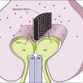
For a retinal prosthesis to function properly, the retina must not be affected by disease to the point where not enough viable cells remain to initiate a neural signal. Postmortem morphometric analysis of the retina of patients with end-stage RP has revealed that 78.4% of inner nuclear and 29.7% of ganglion layer cells were retained compared to only 4.9% of photoreceptors.6,60–63 Also, 93% of RGC were spared and an increase in inner nuclear layer cells (by 10%) were noted in legally blind neovascular AMD patients.64,65 Furthermore, no statistical significance was noted between non-neovascular eyes with geographic atrophy and age-matched controls.64,65 This demonstrates limited transsynaptic neuronal degeneration in the aforementioned retinopathies, and as such, it is theoretically possible to electrically stimulate the remaining retinal neurons to elicit useful visual perceptions. It is important to understand the stages of outer retinal degeneration and the associated anatomical and physiological changes that occur. A comprehensive study has been done by Marc, in which three phases of degeneration and remodeling are classified.66 In the first two phases, photoreceptor stress and death and associated loss of tropic transport are observed. Both bipolar and horizontal cells can actually retract dendrites, while the latter can sprout axonal and dendritic processes that can reach the inner plexiform layer. Müller cells can form a dense fibrotic layer and seal off the subretinal space, electrically isolating implants placed there via the choroid. In phase 3, the number of viable cells of all classes is depleted. Bipolar and amacrine cells can migrate up to the ganglion cell layer and undergo neural rewiring.
Such anatomical changes manifest physiologically. Using a patch clamp technique in a degenerate mouse model, it has been shown that rod bipolar cells lose their sensitivity to the excitatory neurotransmitter glutamate while they increase their response to the inhibitory horizontal cell neurotransmitter GABA.67 Thus, the retinal circuitry is altered both anatomically and physiologically by degeneration.
In spite of these well-documented changes in the inner retina after photoreceptor loss, numerous studies have established the safety and efficacy of electrical stimulation of the retina. Early studies by Humayun and colleagues61–64 established the feasibility of electrical stimulation of the retina. In an operating room setting, hand-held electrodes were inserted into the eye of blind test subjects. The test subjects reported the appearance of small spots of light when the electrodes were activated. The apparent location of the spot of light in general corresponded with the retinal area stimulated. Similar experiments were repeated by other groups.68,69 While these experiments only allowed a few hours of testing in each subject, the critical findings led to the development of chronic implant system.
ARGUS I
At 2 weeks later, under general anesthesia, the implant is placed in a recess well created in the temporal skull, the same way it is done for the cochlear implants.70
To secure and protect the cable, a shallow groove is created along the temporal skull. The cable is then placed in the groove and delivered through a lateral canthotomy into the periocular space. Next, the cable and electrode array are implanted under the four rectus muscles. A complete pars plana vitrectomy is performed and the array introduced to the eye through a 5-mm circumferential scleral incision placed 3 mm posterior to the limbus. The array is placed temporal to the fovea and a single retinal tack inserted to secure the array in place.71 A clinical trial of the ARGUS I device began in 2002 and enrolled six RP patients.
Subjects were able to discriminate between different percepts, identify everyday objects such as a knife, a plate or a cup, and detect the direction of motion. Perceptual thresholds were within safe limits and were stable over time.72,73 Perceptual thresholds correlated with separation (i.e., lift-off) between the electrode array and the retina.73,74 In addition, increasing frequency of pulses lowered the charge per pulse in a predictable way.75
The best visual acuity using the ARGUS I was the maximum allowable by the spacing of electrodes on the array (i.e., 20/4000), but this was only demonstrated in one test subject.76 Adverse events included erosion of the conjunctiva over the cable at the sclerotomy and detachment of one array after one subject incurred blunt ocular trauma (subsequent re-tacking was successful).
ARGUS II
The ARGUS II System (Fig. 126.1) uses an external camera system very similar to ARGUS I, but the implanted part of the device is completely different. The ARGUS II System comprises an encircling band (sclera buckle), an inductive coil and a case containing the electronic components attached to the band, and an integrated ribbon cable and electrode array. The electrode array spans 20° of visual field corner-to-corner. All components fit inside the orbit. The dimensions of the ARGUS II are as follows: electronics case: height, 3.2 mm, diameter, 10.29 mm; receiving coil: height, 16.33 mm, width, 9.7 mm; wire diameter, 0.25 mm; two layers of winding; electrode array 5.5 mm wide and 6 mm long; electrode cable: length, 53.1 mm; width, 1.9 mm.
The ARGUS II is being evaluated in a single-arm, prospective, multicenter clinical trial. A total of 30 subjects were enrolled between June 2007 and August 2009 at 10 clinical centers.77 The electrode array extends across 20° of visual field, measured from corner to corner. All subjects were able to perceive light during electrical stimulation. Experiments documented improvement in object localization. Using a target of a 7 cm white square on a black LCD screen at 30 cm distance, 27 out of 28 subjects (96%) performed better in localizing the object with System ON versus OFF, and no subjects performed significantly better with the System OFF.75 Motion detection was also improved, but to a lesser extent as this is a more difficult task. Using a target of a white bar moving across a black LCD screen, 16 out of 28 subjects (57%) performed this test better with the System ON versus OFF.77 Some subjects report the perception of color, which can be reliably produced under certain conditions.
All subjects’ acuity was measured at worse than 2.9 logMAR in both eyes before implantation. To date, none of the subjects have been able to reliably score on the visual acuity scale in either eye with the System OFF. Seven subjects have been able to reliably score on the scale with the System ON in at least one follow-up time point. The best result to date is 1.8 logMAR (equivalent to Snellen 20/1262).77
Letter reading was tested in 22/30 subjects. Six of these subjects were able to identify any letter of the alphabet at a 63.5% success rate (versus 9.5% with the system off). In all 22 subjects, a small set of eight letters was identified 72.5% correctly, versus 16.8% with the system off. Subjects were free to take as much time as needed to make a judgment. Subjects provided answers after 100 seconds in the full alphabet and 44 seconds in the limited letter set.78 Some subjects were able to put the letters together into words and read sentences.79
Most subjects had no serious adverse events (SAE) and none had any unanticipated adverse events. Of the 30 subjects, 21 subjects (70%) had no SAEs. Three subjects experienced conjunctival erosion due to the extraocular device, this being the most common SAE. All but one was successfully repaired. One device needed to be explanted and this was accomplished without any complications. Other SAEs included three cases of endophthalmitis; each was treated with intravitreal antibiotics and the devices were not explanted and remain functional. There were three cases of hypotony that were resolved with surgical intervention. There was one intraoperative tear treated successfully during surgery with laser retinopexy and two retinal detachments that required subsequent surgery to reattach the retina.80
Intelligent Medical Implants (IMI, Bonn) is developing an active epiretinal prosthesis. The electronics are located in the same location as the ARGUS II implant.81 The device has 49 electrodes and fits entirely inside the orbit. Inductive coupling is used for power and an optical link is used for data. The IMI group has published its surgical approach in animals as well as acute testing procedures and results.
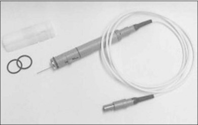
The acute testing surgery was performed under subconjunctival anesthesia. The four eye muscles were fixed, and a pars plana vitrectomy with complete removal of the vitreous and posterior hyaloid were performed. Afterwards, the electrodes were introduced into the eye using one of the sclerotomies with the MESE 12 system (Fig. 126.2). The MESE 12 system is a hand-held surgical instrument for controlled positioning of a microcontact film (BSA) on the surface of the retina. The system must be held by the surgeon during the entire procedure.
The main findings of the chronic implant clinical trial are low thresholds to elicit visual perceptions including form vision and that the implant is reasonably well tolerated by the eye. The device was only activated in the clinic and directly controlled by computer (i.e., no camera). Most implants were removed after a few months, but some have stayed in place for several years. Thresholds in one subject were measured for an extended period and ranged from 8.0 and 35.9 nC (i.e., single µA of current) and were reported as stable over an extended period of testing.82 The subjects report that the phosphenes have different appearances, point-to-point relative location is possible, and simple shapes such as a horizontal bar are recognized when presented.83
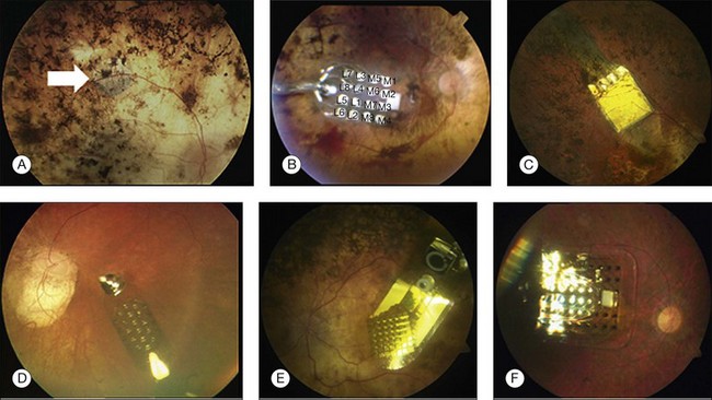
Epi-Ret is the third group developing an active epiretinal prosthesis and the group has implanted six test subjects with implants in 2006. This unique implant is designed to fit entirely inside the eye yet has a provision for external power via an inductive wireless link. The electrode array has 25 electrodes that are slightly protruding from the substrate (Fig. 126.3).
The explantation procedure leaves the tacks in place, only considering removal when the tacks are already loose, and utilizes SF6 gas at 20% for tamponade. At 6 months after explantation, some adverse effects were observed, as gliosis around tacks and epiretinal membranes.84 These investigational implants were only in place for 28 days, which did not allow extensive testing. Consistent with the other epiretinal implant studies, low perceptual thresholds (i.e., single µA of current) were reported.85 The implantation and explantation of the device were successful. Exams during implantation showed that the device remained in position for the entire implant period. Exams 6 months after explantation showed only some proliferation around the retinal tacks, which were left in place.86
Subretinal prosthesis
The subretinal prosthesis, using microphotodiodes (solar cells) alone as a powering mechanism, offers an attractive solution to enhance the vision of patients affected by RP and AMD.87 However, several limitations currently hinder this technology from realizing its goal of being a visual prosthesis. Of primary concern is the inefficiency of current photodiode technology.88 The illumination levels required in order to achieve adequate electrical current generation are not realistically attainable as the solar cells will need to generate electrical energy many orders of magnitude greater than that which is currently viable.89–92
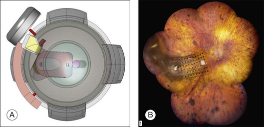
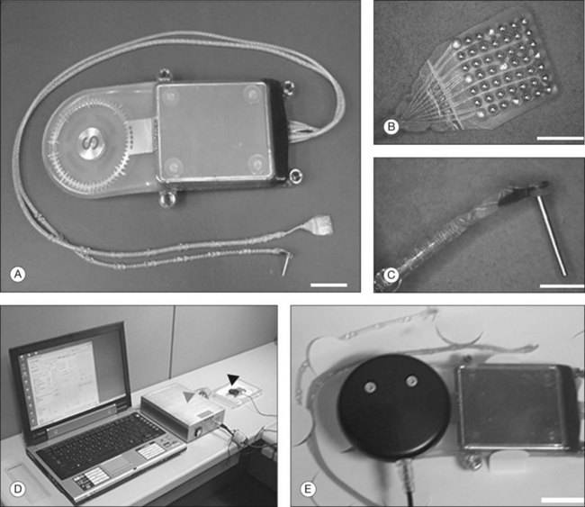
In 2009, Retina Implant AG (RI) started a clinical trial on a new subretinal prosthesis. The new implant has an intraocular part, comprising the array and cable (Fig. 126.4A,B). The microphotodiode array has 1500 pixels elements, with an additional 16 electrodes for direct stimulation tests (Fig. 126.4A). The electrode is placed subretinally, and the cable exits the eye through the pars plana and follows an intraorbital, subcutaneous path to exit behind the earlobe (Fig. 126.4B).
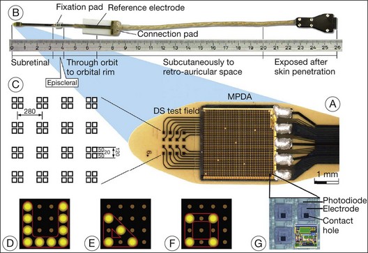
Fig. 126.4 Subretinal implant and cable.
(From Zrenner E, Bartz-Schmidt KU, Benav H, et al. Subretinal electronic chips allow blind patients to read letters and combine them to words. Proc Biol Sci 2011;278:1489–97, with permission from Proc R Soc B, published online November 3, 2010.)
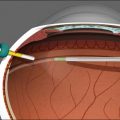
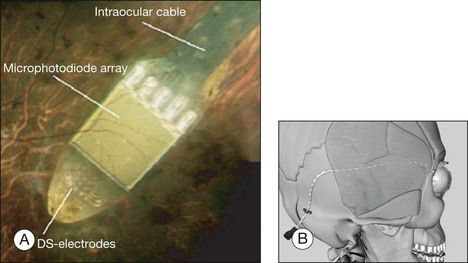
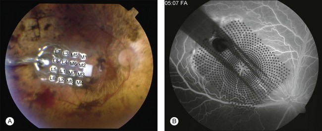
The direct stimulation electrodes are shown magnified, with their respective patterns of stimulation (see Fig. 126.4C–F). Also the microphotodiode array is shown magnified, with its rectangular photodiodes above each squared electrode (Fig. 126.4G). The implantation can be theoretically performed intraocularly, through either a pars plana vitrectomy (PPV) and retinotomy (ab interno), or PPV and a transscleral approach (ab externo)87,93,94; however, to-date, only the ab externo approach has been used in the patients. A 2008 publication detailed the implantation and explantation of the device in humans.95 Hypotensive anesthesia is used to prevent the risk of excessive choroidal bleeding when a 5-mm incision is made in the choroid to introduce the array into the subretinal space. A guide is used to help slide the electrode array under the retina but the procedure is done without direct visualization which can result in multiple attempts to achieve the proper placement of the array under the macula. A silicone oil tamponade is used to prevent retinal detachment. The device remains in position during the time of implantation, and can be explanted by opening and removing the electrode array through the initial choroidal incision. A fundus photo and the placement of the device on the skull are shown in Fig. 126.5.
The RI device has been implanted in 12 subjects, with planned explantation several weeks to 3 months later. Of the first seven subjects, four had electronic hardware problems that precluded further testing of the implanted active chip. By study design, implants were removed after 1 month (first eight implants) and 3 months (last three implants), except for one subject who refused to have the implant removed. Functional testing of the active subretinal implant has demonstrated the ability to see lines and determine the correct orientation of these lines. A scanning laser ophthalmoscope was used to directly activate the subretinal chip and a laser area as small as 100 µm produced a visual perception.87
This group published in 2010 detailed results from the last three (of 12) implant subjects.87 Having gained experience from the first nine subjects, hardware problems were largely avoided in the last three. Also, placement of the subretinal array was more consistent in the macula. Results from these three subjects showed that one patient could identify the direction of the letter “U” when presented in one of four orientations (20/24 times correct), when using the DS electrodes. Patient two of this group could identify letters and combine these into words. All three patients could detect the orientation of gratings, with patient two achieving a visual acuity of logMAR 1.74. This study was the first to report letter reading, providing strong support for functional vision via electrical stimulation. The short duration of implantation (1 or 3 months) limited the amount of data available from these tests. The robustness of this system needs to be improved. The device experienced technical failures at a rate unacceptable for a clinical implant, although fewer problems were noted in later implants.
This group recently announced a second trial with a device that eliminates the percutaneous connector by adding a power module, which is implanted behind the ear.96 A power control module is implanted behind the ear, essentially replacing the percutaneous connector. An external system to provide wireless power is worn around the waist. The rest of the device is as described above. This study found that five subjects were able to identify various objects in their vicinity (plates, fruit, and desk items). Additionally, the subjects recognized borders of cars and sidewalks and were able to utilize shadows in an outdoor environment.
The new-generation implants have the power and data receiver coils in the anterior part of the eye, surrounding the cornea, just behind the conjunctiva. The case is now made of titanium, and since the electrode implantation is in the same quadrant as the electronics, the surgical access to create a scleral flap and insert the array has been made easier.97
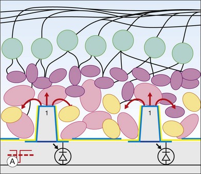
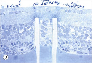
Palanker et al. suggested a new design for a retinal prosthesis. It consists of a system with 2500 electrodes/mm2 (corresponding to a maximum visual acuity of 20/80), with two basic geometries providing optimal proximity to retinal neural cells: perforated membranes and protruding electrode arrays.98 In an in vitro experiment placing retinas with the photoreceptor side down in contact with a 13 µm implant with 40 µm apertures, retinal tissue migration was observed in all samples of rat, chicken, and rabbit retina (Fig. 126.6). Migration occurred through pores >5 µm.99
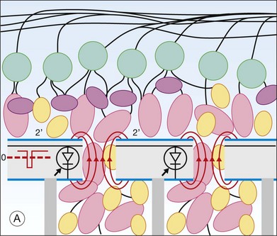
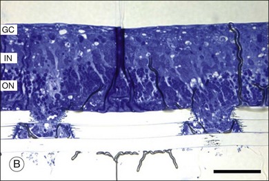
The in vivo model was studied in RCS rats with subretinal Mylar films with pores of 15–40 µm, showing robust migration of the inner retinal layer after 5–9 days.99 Some questions arise from this approach, mainly if the retinal tissue will remain viable after migrating through the pores, if the circuitry will be kept functional, and lastly if the migrated tissue will differentiate into fibrous tissue. Another approach consists of subretinal implants with protruding electrodes, so that cells can migrate to the spaces between the electrodes, similar to the migration observed in the perforated membrane. In vivo implantation on RCS rats of 70 µm in height with 10 µm in diameter arrays showed after 15 days penetration of the pillars into the inner plexiform layer and the retina well preserved (Fig. 126.7).100
Recent alternative approaches
Investigators from Japan have recently collaborated on a relatively new approach to artificial vision they term suprachoroidal transretinal stimulation (STS) (Fig. 126.8). They have hypothesized that placing a stimulating electrode in the suprachoroidal space or in the fenestrated sclera along with a ground electrode in the vitreous cavity, may allow for a less-invasive method to achieve functional percepts. The advantages to such an approach are several. First of all, the surgery is less complicated. Second, the electrodes are less invasive to the retina. Third, the electrodes are relatively easy to remove or replace if damaged.101,102
However, this approach remains to be proven over long-term implantation. Specifically, because the electrodes are further from the target neurons, they should need to deliver higher currents and the current spread should be greater, therefore limiting the resolution.101,102
Initially, STS has been investigated in the Royal College of Surgeons (RCS) rats and rabbits. In the RCS rats, the investigators studied threshold intensities of electrically evoked potentials (EEPs) from the superior colliculus (SC). It was found that the response to the STS was recorded in the localized retinotopically corresponding SC areas, suggesting that the focal stimulation to the degenerated retina effectively elicits artificial vision in the RCS rats. Similar findings were noted in rabbits as well. The threshold intensity of the EEPs was 5–10 nC of electrical charge, suggesting that stimulation via STS may be attained with relatively low stimulating current.101,102 However, we should note that rabbit sclera and retina are thinner than in humans, thus partially accounting for the relatively low stimulating current in this study.
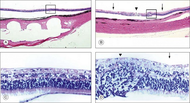
Recently, the results from the last long-term implantation in dogs were published.103 STS microelectrode arrays were implanted into a scleral pocket of beagle dogs and were kept in place for 3 months. The electrode array and the return electrode were connected to the extraocular stimulator by a multiwire cable, connected wirelessly to an extra corporeal processor and transmitter. The electrode array measured 6 × 6 × 0.5 mm, with 49 platinum electrodes in a 7 × 7 arrangement fixed in a clear silicone rubber platform coated with Parylene. The stimulating electrode was 0.5 mm in diameter and 0.5 mm in length and the distances between the centers of electrodes were 0.75 mm and the return platinum electrode placed in the vitreous cavity were 6.5 mm in length and 0.5 mm in diameter. Nine of the electrodes on the array were electrically active for this experiment. After 3 months all three prostheses were safely implanted with no intraoperative complications, the position of the eyes was maintained orthophoric without proptosis during the follow-up period and all the wounds healed properly with no sign of infections or wound dehiscence. The notch of the array could be seen on the fundus examination on dogs two and three. The ERGs had the normal a-wave and b-waves, and the shape did not differ from the ERGs recorded from the unoperated fellow eye 3 months after the implantation in all three animals. Histologic sections from two implanted and control eyes showed no obvious changes in the structure of retina and choroid beneath the electrode array in dogs one and three; however, pathologic changes were detected in the retina of dog two (Fig. 126.9). The retinal and choroidal architecture was destroyed due to the mechanical pressure, according to the authors.103
In a 2011 paper, Fujikado et al. reported results of semi-chronic, suprachoroidal implantation of two patients with RP. The visual acuity of the patients before implantation was light perception. The 49-electrode array (5.7 × 4.6 × 0.5 mm) was placed in the suprachoroidal space without causing retinal detachment or vitreous hemorrhage, and the internal devices of the implant were implanted under the skin on the temporal side of the head. The implants remained functional for the 4 weeks of the study. After 5–7 weeks the implants were surgically removed (first and second patient, respectively).104
Phosphenes were elicited by currents delivered through six electrodes in patient one and through four electrodes in patient two. The success of discriminating 2 bars was better than the chance level in both patients. In patient two, the success of a grasping task was better than the chance level, and the success rate of identifying a white bar on a touch panel increased with repeated testing.104
An Australian group is also investigating the feasibility of a suprachoroidal placement of the electrode array.105 The surgical procedure consists of lateral canthotomy followed by a full-thickness sclerotomy, exposing the choroid. A “pocket” is created in the suprachoroidal space, for the insertion of a flexible electrode array 15–17 mm into the eye, beneath the area centralis. The array is then sutured in place, and platinum ball electrodes (1.5 mm diameter) were placed in the vitreous cavity and in the suprachoroidal space, next to the electrode, to act as return electrodes for electrical stimulation. The animal was then placed in a stereotaxic frame and kept in a dark, electrically shielded Faraday room.
A platinum electrode was implanted in the skin of the back of the neck, to serve as reference, and a craniotomy was them performed to expose the primary visual cortex, and placement of the platinum macroelectrode, in the region corresponding to the macular region of the retina. The cortical electrode was used for all evoked potential recordings due to the full-field flashes and electrical stimulation of the electrode.105 The authors report that charge thresholds depended only upon the number of sites stimulated in parallel. Electrode size, pulse width, and position of the return electrode did not affect charge threshold.
The transchoroidal systems described above represent a new approach that has some advantages compared with the subretinal and epiretinal approaches. For example the ab externo approach through the sclera, potentially less complicated than the ab interno approach, along with a more stable positioning of the electrode on the suprachoroidal space decreases the risk of retinal detachment. However, given the distance between the retina and sclera (250–300 µm in cats106; 204–490 µm in humans107), it is suggested that such prosthesis will not achieve the same resolution as the epiretinal or subretinal prostheses.108 Also, higher currents will be required for stimulation, due to all the layers interposed between the array and the ganglion/bipolar cells. However, animal studies already showed the ability to evoke cortical potentials using suprachoroidal of the outer nuclear layer, outer plexiform layer and inner nuclear layer stimulation.109–113
The Microfluidic Retinal Prosthesis is an alternative approach that will mimic normal chemical signaling between neurons in the retina and brain.104–109
The overall hypothesis is that digital images may be transposed into neurochemical signals through a microfluidic chip, chronically implanted in the subretinal space. The design of their neurotransmitter-based visual prosthesis utilizes a multitude of microfluidic orifices that create a two-dimensional array of “chemical pixels”, arranged to create an image analogous to an inkjet printer, delivering neurotransmitter to the retina or brain. The device design eliminates the need for mechanical valves by using an inactive or “caged” form of neurotransmitter that is photoactivated by ultraviolet light.114,115
Furthermore, a microfluidic retinal prosthesis chip may allow for a number of unique features, including the ability to bundle electrical stimulation with neurotransmitter stimulation and the simultaneous, or independent, delivery of therapeutic drugs. In this way, deoxyribonucleic and ribonucleic acids (DNA and RNA), peptides, neurotransmitters, and hormones can all be packaged as phototriggered caged pro-drugs. Then these photoactivated molecules can be delivered via an “uncage-and-release” microfluidic retinal implant technology allowing for in vivo photoactivation and release of drugs upon the retinal surface.116–130
Electrotherapeutics
Electrotherapeutics
Initially developed as a retinal prosthesis, the ASR was implanted (subretinal and extramacular) in ten patients in a single-center study and then 20 subjects in a multicenter study. The 3-mm-diameter implants had 3500 microphotodiodes that generated stimulating current in response to incident light (Fig. 126.3). Results from the first six subjects were published in 2004, reporting that all six described subjective improvements in vision. Three of the six had improved early treatment diabetic retinopathy study (ETDRS) scores, while one in six had an enlarged visual field postoperatively. However, the improved vision included areas of the visual field far from the implant location. The authors concluded that the subretinal ASR implant was not directly mediating artificial vision (i.e., electrical stimulation via the ASR did not directly affect visual perception). Instead, the ASR’s presence in the subretinal space was acting via an indirect effect, possibly through release of growth factors, and improving the health of the retina.131
The theoretical current output of a subretinal microphotodiode in a sunny environment is <1 nA (nano Ampere) (10−9),132 far below what is required for electrical activation of nerves. Thus, the ASR cannot be considered a retinal prosthesis.
The multicenter study provided additional results from visual task performance and more detail on the surgical procedure. Adverse events included three cases of ASR migration; two incidences of fracture of the device during implantation (the damaged device was easily removed), and six visually significant cataracts (versus three in the fellow eyes).133 The most recent report from the group states that visual improvements are maintained in the original six implant subjects from the single-center trial.134
Optogenetics
A quickly emerging alternative to an implanted bioelectronic device is the “optogenetic” approach. Pioneered by Deisseroth,135–137 the optogenetic technique modifies individual neurons to include light-sensitive ion channels, the most common being channel rhodopsin 2 (ChR2). When light of a specific wavelength is shone on to the cell, ChR2 opens resulting in depolarization of the cell. Viral vectors such as adeno associated virus are used to get the ChR2 DNA into the cell. Bi et al. first demonstrated that this could be used to modify retinal ganglion cells, showing that light-evoked neural responses were present in a mouse model of retinal degeneration when the mouse RGCs contained ChR2.138 Others have extended this initial work to show that behavioral responses were preserved in rd1 mice139 and that photoreceptor nuclei cell bodies could be modified and initiate a neural response even in the absence of outer segments.140 Incorporating a second light-sensitive channel (Halorhodopsin) into the dendrites of a retinal ganglion cell and ChR2 in the soma, to enable a center-surround response dependent on the wavelength of light, the optogenetic approach has some significant advantages over the bioelectronic approach. By making each cell light sensitive, vision can potentially be restored to near normal acuity. Also, using light as the activating signal allows the optics of the eye to be used to focus the image on the retina. In other words, the optogenetic approach can come much closer to restoring natural vision, versus artificial vision provided by bioelectronic approaches. However, many potential challenges must be overcome before optogenetic approaches can be clinically viable. The main issue relates to sensitivity. Currently, modified cells require bright, blue light (460 nm) to be activated, roughly four orders of magnitude above cone light sensitivity threshold in normally sighted people. It is not clear how such intense light would interact with a diseased retina, with remnant light sensitivity. Given that photophobia is sometimes a symptom of RP, then directing a bright light into the photophobic patient’s eye is unlikely to provide a benefit. In addition, it is unclear if the modified cells permanently maintain this light sensitivity, or if reinjection is required.
Conclusions from clinical trials
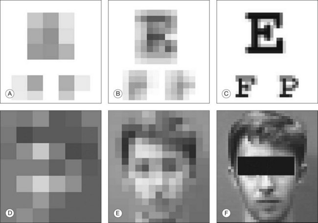
Retinal prostheses have achieved two major milestones in recent years. First, at least in the ARGUS series epiretinal prostheses, we see continued improvement in visual acuity with increasing number and density of electrodes. Even though the visual acuity is still poor relative to normal vision, the subjects who have received either the ARGUS or Retinal Implant AG device can read large letters using their implants. The challenge is how to continue this forward momentum and have most of the implant recipients benefit through the use of retinal prostheses in their activities of daily living. Moreover, can future implants continue to improve visual acuity and some day, even provide color vision? Simulations of artificial vision,18,24 have predicted that 600–1000 individual pixels may be need to enable face recognition and large font reading (Figs 126.10, 126.11). If optogenetic therapies can be made more sensitive, then these may provide restoration of near natural vision, but this is decades from being realized. The development of retinal prostheses to generate artificial vision for the blind is indeed a complex, long-term, expensive, and interdisciplinary undertaking, but the new clinical trials data provide hope that in the near future, doctors and patients can present the long-awaited “good news” to their patients.
1 Ross RD. Is perception of light useful to the blind patient? Arch Ophthalmol. 1998;116:236–238.
2 Berson EL, Rosner B, Sandberg MA, et al. A randomized trial of Vitamin A and Vitamin E supplementation for retinitis. Arch Ophthalmol. 1993;111:761–772.
3 Sharma RK, Ehinger B. Management of hereditary retinal degenerations: present status and future directions. Surv Ophthalmol. 1999;43:427–444.
4 del Cerro M, Gash DM, Rao GN, et al. Retinal transplants into the anterior chamber of the rat eye. Neuroscience. 1987;21:707–723.
5 Bunker CH, Berson EL, Bromley WC, et al. Prevalence of retinitis pigmentosa in Maine. Am J Ophthalmol. 1984;97:357–365.
6 Curcio CA, Medeiros NE, Millican CL. Photoreceptor loss in age-related macular degeneration. Investig Ophthalmol Vis Sci. 1996;37:1236–1249.
7 Humayun MS, de Juan E, Jr. Artificial vision. Eye. 1998;12:605–607.
8 Rosenfeld PJ, Brown DM, Heier JS, et al. Ranibizumab for neovascular age-related macular degeneration. MARINA Study Group. N Engl J Med. 2006;355:1419–1431.
9 Brown DM, Kaiser PK, Michels M, et al. Ranibizumab versus verteporfin for neovascular age-related macular degeneration. ANCHOR Study Group. N Engl J Med. 2006;355:1432–1444.
10 CATT Research Group. Ranibizumab and bevacizumab for neovascular age-related macular degeneration. N Engl J Med. 2011;364:1897–1908.
11 Imamura Y, Engelbert M, Iida T, et al. Polypoidal choroidal vasculopathy: a review. Surv Ophthalmol. 2010;55:501–515.
12 Chew EY, Lindblad AS, Clemons T, Age-Related Eye Disease Study Research Group. Summary results and recommendations from the age-related eye disease study. Arch Ophthalmol. 2009;127:1678–1679.
13 Stein L, Roy K, Lei L, et al. Clinical gene therapy for the treatment of RPE65-associated Leber congenital amaurosis. Expert Opin Biol Ther. 2011;11:429–439.
14 Li X, Li W, Dai X, et al. Gene therapy rescues cone structure and function in the 3-month-old rd12 mouse: a model for midcourse RPE65 Leber congenital amaurosis. Invest Ophthalmol Vis Sci. 2011;52:7–15.
15 Cideciyan AV. Leber congenital amaurosis due to RPE65 mutations and its treatment with gene therapy. Prog Retin Eye Res. 2010;29:398–427.
16 Maguire AM, High KA, Auricchio A, et al. Age-dependent effects of RPE65 gene therapy for Leber’s congenital amaurosis: a phase 1 dose-escalation trial. Lancet. 2009;374:1597–1605. [Erratum: 2010;375:30.]
17 Foerster O. Beitrage zur pathophysiologie der sehbahn und der spehsphare. J Psychol Neurol. 1929;39:435–463.
18 Brindley G. The number of information channels needed for efficient reading. J Physiol. 1965;177:44.
19 Cha K, Horch K, Normann RA. Simulation of a phosphene-based visual field: visual acuity in a pixelized vision system. Ann Biomed Eng. 1992;20:439–449.
20 Cha K, Horch KW, Normann RA. Mobility performance with a pixelized vision system. Vision Res. 1992;32:1367–1372.
21 Cha K, Horch KW, Normann RA, et al. Reading speed with a pixelized vision system. J Opt Soc Am A. 1992;9:673–677.
22 Thompson RW, Jr., Barnett GD, Humayun MS, et al. Facial recognition using simulated prosthetic pixelized vision. Invest Ophthalmol Vis Sci. 2003;44:5035–5042.
23 Hayes JS, Yin VT, Piyathaisere D, et al. Visually guided performance of simple tasks using simulated prosthetic vision. Artif Organs. 2003;27:1016–1028.
24 Brindley GS, Rushton D. Implanted stimulators of the visual cortex as visual prosthetic devices. Trans Am Acad Ophthalmol Otolaryngol. 1974:741–745.
25 Brindley GS. Sensations produced by electrical stimulation of the occipital poles of the cerebral hemispheres, and their use in constructing visual prostheses. Ann R Coll Surg Engl. 1970;47:106–108.
26 Brindley GS, Lewin WS. The sensations produced by electrical stimulation of the visual cortex. J Physiol. 1968;196:479–493.
27 Brindley GS, Lewin WS. The visual sensations produced by electrical stimulation of the medial occipital cortex. J Physiol. 194, 1968. 54–5P
28 Dobelle WH, Mladejovsky MG. Phosphenes produced by electrical stimulation of human occipital cortex, and their application to the development of a prosthesis for the blind. J Physiol. 1974;243:553–576.
29 Dobelle WH, Mladejovsky MG, Evans JR, et al. “Braille” reading by a blind volunteer by visual cortex stimulation. Nature. 1976;259:111–112.
30 Dobelle WH, Quest DO, Antunes JL, et al. Artificial vision for the blind by electrical stimulation of the visual cortex. Neurosurgery. 1979;5:521–527.
31 Dobelle WH. Artificial vision for the blind by connecting a television camera to the visual cortex. ASAIO J. 2000;46:3–9.
32 Pollen DA. Responses of single neurons to electrical stimulation of the surface of the visual cortex. Brain Behav Evol. 1977;14:67–86.
33 Schmidt EM, Bak MJ, Hambrecht FT, et al. Feasibility of a visual prosthesis for the blind based on intracortical microstimulation of the visual cortex. Brain. 1996;119:507–522.
34 Maynard EM. Visual prostheses. Annu Rev Biomed Eng. 2001;3:145–168.
35 Bak M, Girvin JP, Hambrecht FT, et al. Visual sensations produced by intracortical microstimulation of the human occipital cortex. Med Biol Eng Comput. 1990;28:257–259.
36 Maynard EM, Nordhausen CT, Normann RA. The Utah intracortical Electrode Array: a recording structure for potential brain-computer interfaces. Electroencephalogr Clin Neurophysiol. 1997;102:228–239.
37 Uematsu S, Chapanis N, Gucer G, et al. Electrical stimulation of the cerebral visual system in man. Confin Neurol. 1974;36:113–124.
38 Rousche PJ, Normann RA. Chronic intracortical microstimulation (ICMS) of cat sensory cortex using the Utah Intracortical Electrode Array. IEEE Trans Biomed Eng. 1999;7:56–68.
39 McCreery DB, Yuen TG, Agnew WF, et al. A characterization of the effects on neuronal excitability due to prolonged microstimulation with chronically implanted microelectrodes. IEEE Transactions on Biomedical Engineering. 1997;44:931–939.
40 Agnew WF, Yuen TG, McCreery DB, et al. Histopathologic evaluation of prolonged intracortical electrical stimulation. Exp Neurol. 1986;92:162–185.
41 Weiland JD, Anderson DJ. Chronic neural stimulation with thin-film, iridium oxide electrodes. IEEE Trans Biomed Eng. 2000;47:911–918.
42 Normann RA, Maynard EM, Rousche PJ, et al. A neural interface for a cortical vision prosthesis. Vision Res. 1999;39:2577–2587.
43 Margalit E, Maia M, Weiland JD, et al. Retinal prosthesis for the blind. Survey of Ophthalmology. 2002;47:335–356.
44 Shandurina AN. Restoration of visual and auditory function using electrostimulation. Fiziol Cheloveka. 1995;21:25–29.
45 Shandurina AN, Panin AV, Sologubova EK, et al. Results of the use of therapeutic periorbital electrostimulation in neurological patients with partial atrophy of the optic nerves. Neurosci Behav Physiol. 1996;26:137–142.
46 Veraart C, Raftopoulos C, Mortimer JT, et al. Visual sensations produced by optic nerve stimulation using an implanted self-sizing spiral cuff electrode. Brain Res. 1998;813:181–186.
47 Naples GG, Mortimer JT, Scheiner A, et al. A spiral nerve cuff electrode for peripheral nerve stimulation. [comment]. IEEE Trans Biomed Eng. 1988;35:905–916.
48 Sweeney JD, Mortimer JT. An asymmetric two electrode cuff for generation of unidirectionally propagated action potentials. IEEE Trans Biomed Eng. 1986;33:541–549.
49 Ungar IJ, Mortimer JT, Sweeney JD. Generation of unidirectionally propagating action potentials using a monopolar electrode cuff. Ann Biomed Eng. 1986;14:437–450.
50 Buckett JR, Peckham PH, Thrope GB, et al. A flexible, portable system for neuromuscular stimulation in the paralyzed upper extremity. IEEE Trans Biomed Eng. 1988;35:897–904.
51 Delbeke J, Oozeer M, Veraart C. Position, size and luminosity of phosphenes generated by direct optic nerve stimulation. Vision Res. 2003;43:1091–1102.
52 Cuoco FA, Jr., Durand DM. Measurement of external pressures generated by nerve cuff electrodes. IEEE Trans Biomed Eng. 2000;8:35–41.
53 Branner A, Normann RA. A multielectrode array for intrafascicular recording and stimulation in sciatic nerve of cats. Brain Res Bull. 2000;51:293–306.
54 Veraart C, Wanet-Defalque MC, Gerard B, et al. Pattern recognition with the optic nerve visual prosthesis. Artif Organs. 2003;27:996–1004.
55 Potts AM, Inoue J. The electrically evoked response of the visual system (EER). III. Further contribution to the origin of the EER. Invest Ophthalmol. 1970;9:814–819.
56 Potts AM, Inoue J. The electrically evoked response (EER) of the visual system. II. Effect of adaptation and retinitis pigmentosa. Invest Ophthalmol. 1969;8:605–612.
57 Potts AM, Inoue J, Buffum D. The electrically evoked response of the visual system (EER). Invest Ophthalmol. 1968;7:269–278.
58 Knighton RW. An electrically evoked slow potential of the frog’s retina. II. Identification with PII component of electroretinogram. J Neurophysiol. 1975;38:198–209.
59 Knighton RW. An electrically evoked slow potential of the frog’s retina. I. Properties of response. J Neurophysiol. 1975;38:185–197.
60 del Cerro M, Gash DM, Rao GN, et al. Retinal transplants into the anterior chamber of the rat eye. Neuroscience. 1987;21:707–723.
61 Humayun MS, Prince M, de Juan E, Jr., et al. Morphometric analysis of the extramacular retina from postmortem eyes with retinitis pigmentosa. Invest Ophthalmol Vis Sci. 1999;40:143–148.
62 Santos A, Humayun MS, de Juan E, Jr., et al. Preservation of the inner retina in retinitis pigmentosa. A morphometric analysis. Arch Ophthalmol. 1997;115:511–515.
63 Stone JL, Barlow WE, Humayun MS, et al. Morphometric analysis of macular photoreceptors and ganglion cells in retinas with retinitis pigmentosa. Arch Ophthalmol. 1992;110:1634–1639.
64 Kim SY, Sadda S, Humayun MS, et al. Morphometric analysis of the macula in eyes with geographic atrophy due to age-related macular degeneration. Retina. 2002;22:464–470.
65 Kim SY, Sadda S, Pearlman J, et al. Morphometric analysis of the macula in eyes with disciform age-related macular degeneration. Retina. 2002;22:471–477.
66 Marc RE. Neural remodeling in retinal degeneration. Prog Retin Eye Res. 2003;22:607.
67 Varela C, Igartua I, De La Rosa EJ, et al. Functional modifications in rod bipolar cells in a mouse model of retinitis pigmentosa. Vision Res. 2003;43:879–885.
68 Rizzo JF, 3rd., Wyatt J, Loewenstein J, et al. Methods and perceptual thresholds for short-term electrical stimulation of human retina with microelectrode arrays. Invest Ophthalmol Vis Sci. 2003;44:5355–5361.
69 Rizzo JF, 3rd., Wyatt J, Loewenstein J, et al. Perceptual efficacy of electrical stimulation of human retina with a microelectrode array during short-term surgical trials. Invest Ophthalmol Vis Sci. 2003;44:5362–5369.
70 Webb RL, Pyman BC, Franz BK-HG, et al. The surgery of cochlear prostheses. In: Clark GM, Tong YC, Patrick JF. Cochlear prostheses. London: Churchill Livingstone; 1990:153–180.
71 Humayun MS. Visual perception in a blind subject with a chronic microelectronic retinal prosthesis. Vision Res. 2003;43:2573–2581.
72 Merrill DR. Electrical stimulation of excitable tissue: design of efficacious and safe protocols. J Neurosci Meth. 2005;141:171–198.
73 Mahadevappa M, Weiland JD, Yanai D, et al. Perceptual thresholds and electrode impedance in three retinal prosthesis subjects. IEEE Trans Neural Syst Rehabil Eng. 2005;13:201–206.
74 de Balthasar C, Patel S, Roy A, et al. Factors affecting perceptual thresholds in epiretinal prostheses. Invest Ophthalmol Vis Sci. 2008;49:2303–2314.
75 Ahuja AK, Dorn JD, Caspi A, et al. Blind subjects implanted with the Argus II retinal prosthesis are able to improve performance in a spatial-motor task. Br J Ophth. 2011;95:539–543.
76 Caspi A, Dorn JD, McClure KH, et al. Feasibility study of a retinal prosthesis: spatial vision with a 16-electrode implant. Arch Ophthalmol. 2009;127:398–401.
77 Humayun MS, Argus II Study Group. Interim performance results from the Second Sight Argus II Retinal Prosthesis Study. Invest Ophthalmol Vis Sci. 2010;51:2022.
78 da Cruz L, Argus II Study Group. Patients blinded by outer retinal dystrophies are able to identify letters using the Argus II retinal prosthesis system. Invest Ophthalmol Vis Sci. 2010;51:2023.
79 Humayun MS. Interim performance results from the Second Sight Argus II. Retinal Prosthesis Study; 2011.
80 Humayun MS. Oral presentation. American Society of Retina Specialists. 2009.
81 Hornig R, Zehnder T, Velikay-Parel M, et al. The IMI Retinal Implant System. In: Humayun MS, Weiland JD, Chader G, et al. Artificial sight: basic research, biomedical engineering, and clinical advances. New York: Springer, 2007.
82 Richard G. Long-term stability of stimulation thresholds obtained from a human patient with a prototype of an epiretinal retina prosthesis. Invest Ophthalmol Vis Sci. 2009. E-Abstract 4580
83 Richard G. Chronic epiretinal chip implant in blind patients with retinitis pigmentosa: long-term clinical results. Invest Ophthalmol Vis Sci. 48, 2007. E-Abstract 666
84 Roessler G, Laube T, Brockmann C, et al. Implantation and explantation of a wireless epiretinal retina implant device: observations during the EPIRET3 Prospective Clinical Trial. Invest Ophthalmol Vis Sci. 2009;50:3003–3008.
85 Klauke S. Stimulation with a wireless intraocular epiretinal implant elicits visual percepts in blind humans. Invest Ophthalmol Vis Sci. 2011;52:449–455.
86 Roessler G. Implantation and explantation of a wireless epiretinal retina implant device: observations during the EPIRET3 prospective clinical trial. Invest Ophthalmol Vis Sci. 2009;50:3003–3008.
87 Zrenner E, Bartz-Schmidt KU, Benav H, et al. Subretinal electronic chips allow blind patients to read letters and combine them to words. Proc Biol Sci. 2011;278:1489–1497.
88 Benav H. Restoration of useful vision up to letter recognition capabilities using subretinal microphotodiodes. Conf Proc IEEE Eng Med Biol Soc. 2010;2010:5919–5922.
89 Peyman G, Chow AY, Liang C, et al. Subretinal semiconductor microphotodiode array. Ophthalmic Surg Lasers. 1998;29:234–241.
90 Chow AY, Peyman GA, Pollack JS, et al. Safety, feasibility and efficacy of subretinal artificial silicon retina prosthesis for the treatment of patients with retinitis pigmentosa. Invest Ophthalmol. 2002;43:114.
91 Chow AY, Pardue MT, Perlman JI, et al. Subretinal implantation of semiconductor-based photodiodes: durability of novel implant designs. J Rehabil Res Dev. 2002;39:313–321.
92 Schwahn HN, Gekeler F, Kohler K, et al. Studies on the feasibility of a subretinal visual prosthesis: data from Yucatan micropig and rabbit. Graefes Arch Clin Exp Ophthalmol. 2001;239:961–967.
93 Zrenner E, Bartz-Schmidt KU, Benav H, et al. Subretinal electronic chips allow blind patients to read letters and combine them to words. Proc Biol Sci. 2011;278:1489–1497. Electronic Supplementary Material at http://rspb.royalsocietypublishing.org/lookup/doi/10.1098/rspb.2010.1747
94 Kusnyerik A, Greppmaier U, Klose U, et al. Preoperative 3D planning of implantation of a subretinal prosthesis using MRI Data. Invest Ophthalmol Vis Sci. 49, 2008. E-3025
95 Besch D. Extraocular surgery for implantation of an active subretinal visual prosthesis with external connections: feasibility and outcome in seven patients. Br J Ophthalmol. 2008;92:1361–1368.
96 Zrenner E, Bruckmann A, Greppmaier U, et al. Improvement of visual orientation and daily skills mediated by subretinal electronic implant alpha IMS in previously blind RP patients. ARVO Meeting. 2011. 457/D1104
97 Shire DB, Doyle P, Kelly SK, et al. In vivo operation of the Boston 15-channel wireless sub retinal visual prosthesis. Human Vision and Electronic Imaging. 2010. 7527SPIE:752705
98 Palanker D, Huie P, Vankov A, et al. Migration of retinal cells through a perforated membrane: implications for a high-resolution prosthesis. Invest Ophthalmol Vis Sci. 2004;45:3266–3270.
99 Palanker D, Vankov A, Huie P, et al. Design of a high-resolution optoelectronic retinal prosthesis. J Neural Eng. 2005;2:S105–S120.
100 Palanker DV, Huie P, Vankov AB, et al. Attracting retinal cells to electrodes for high-resolution stimulation. Proc SPIE. 2004:5314.
101 Morimoto T, Miyoshi T, Fujikado T, et al. Electrical stimulation enhances the survival of axotomized retinal ganglion cells in vivo. Neuroreport. 2002;13:227–230.
102 Fujikado T, Tano Y. The Japan experience: epiretinal prosthesis. American Academy of Ophthalmology, Subspecialty Day, November 15, 2003.
103 Morimoto T, Kamei M, Nishida K, et al. Chronic implantation of newly developed suprachoroidal-transretinal stimulation prosthesis in dogs. Invest Ophthalmol Vis Sci. 2011;52:6785–6792.
104 Fujikado T, Kamei M, Sakaguchi H, et al. Testing of semichronically implanted retinal prosthesis by suprachoroidal-transretinal stimulation in patients with retinitis pigmentosa. Invest Ophthalmol Vis Sci. 2011;52:4726–4733.
105 Shivdasani MN, Luu CD, Cicione R, et al. Evaluation of stimulus parameters and electrode geometry for an effective suprachoroidal retinal prosthesis. J Neural Eng. 2010;7:036008.
106 Tusa RJ, Palmer LA, Rosenquist AC. The retinotopic organization of area 17 (striate cortex) in the cat. J Comp Neurol. 1978;177:213–235.
107 Brown JS, Flitcroft DI, Ying GS, et al. In vivo human choroidal thickness measurements: evidence for diurnal fluctuations. Invest Ophthalmol Vis Sci. 2009;50:5–12.
108 Kanda H. Electrophysiological Studies of the Feasibility of Suprachoroidal-Transretinal Stimulation for Artificial Vision in Normal and RCS Rats. Invest Ophthalmol Vis Sci. 2004;45:560–566.
109 Nakauchi K. Transretinal electrical stimulation by an intrascleral multichannel electrode array in rabbit eyes. Graefe’s Arch Clin Exp Ophthalmol. 2005;243:169–174.
110 Nakauchi K, Fujikado T, Kanda H, et al. Threshold suprachoroidal-transretinal stimulation current resulting in retinal damage in rabbits. J Neural Eng. 2007;4:S50–S57.
111 Wong YT, Chen SC, Kerdraon YA, et al. Efficacy of supra-choroidal, bipolar, electrical stimulation in a vision prosthesis. Conf Proc IEEE Eng Med Biol Soc. 2008:1789–1792. 2008
112 Wong YT, Chen SC, Seo JM, et al. Focal activation of the feline retina via a suprachoroidal electrode array. Vis Res. 2009;49:825–833.
113 Sakaguchi H, Fujikado T, Fang X, et al. Transretinal electrical stimulation with a suprachoroidal multichannel electrode in rabbit eyes. Jpn J Ophthalmol. 2004;48:256–261.
114 Iezzi R, Safadi M, Miller J, et al. Feasibility of retinal and cortical prosthesis based upon spatiotemporally controlled release of L-glutamate. Invest Ophthalmol Vis Sci. 2001;42:S941.
115 Auner GW, Safadi MR, Siy P, et al. Nano- and micro- system neuro interfacing electrode arrays for the retina. Invest Opthalmol Vis Sci. 2001;42:S815.
116 Iezzi R, Abrams GW. The Detroit Program: The Bundled Neurotransmitter Chip. Roles for a Microfluidic Retinal Prosthesis Implant. American Academy of Ophthalmology, Subspecialty Day, November 15, 2003.
117 Arroyo JG, Jones PB, Porter NA, et al. In vivo photoactivation of caged-thrombin. Thromb Haemost. 1997;78:791–793.
118 Ando H, Furuta T, Tsien RY, et al. Photo-mediated gene activation using caged RNA/DNA in zebrafish embryos. Nat Genet. 2001;28:317–325.
119 Givens RS, Jung A, Park C-H, et al. New photoactivated protecting groups: 7. p-hydroxyphenacyl – a phototrigger for excitatory amino acids and peptides. J Am Chem Soc. 1997;199:8369–8370.
120 Givens RS, Park CH. p-hydroxyphenacyl ATP – a new phototrigger. Tetrahedron Lett. 1996;37:6259–6262.
121 Givens RS, Weber JFW, Conrad PG, II., et al. New phototriggers 9: p-hydroxyphenacyl as a C-terminal photoremovable protecting group for oligopeptides. J Am Chem Soc. 2000;122:2687–2697.
122 Givens RS, Weber JF, Jung AH, et al. New photoprotecting groups: desyl and p-hydroxyphenacyl phosphate and carboxylate esters. Methods Enzymol. 1998;291:1–29.
123 Godwin DW, Che D, O’Malley DM, et al. Photostimulation with caged neurotransmitters using fiber optic lightguides. J Neurosci Methods. 1997;73:91–106.
124 Kaplan JH, Somlyo AP. Flash photolysis of caged compounds: new tools for cellular physiology. Trends Neurosci. 1989;12:54–59.
125 Kandler K, Katz LC, Kauer JA. Focal photolysis of caged glutamate produces long-term depression of hippocampal glutamate receptors. Nat Neurosci. 1998;1:119–123.
126 Katz LC, Dalva MB. Scanning laser photostimulation: a new approach for analyzing brain circuits. J Neurosci Methods. 1994;54:205–218.
127 Marriott G, Ottl J, Heidecker M, et al. Light-directed activation of protein activity from caged protein conjugates. Methods Enzymol. 1998;291:95–116.
128 Marriott G, Walker JW. Caged peptides and proteins: new probes to study polypeptide function in complex biological systems. Trends Plant Sci. 1999;4:330–334.
129 Vastag B. Future eye implants focus on neurotransmitters. JAMA. 2002;288:1833–1834.
130 Leng T, Huie P, Mehenti NZ, et al. Directed ganglion cell growth and stimulation with microcontact printing as a prototype visual prosthesis interface. Invest Ophthalmol Vis Sci. 43, 2002. E-4454
131 Ciavatta VT, Kim M, Wong P, et al. Retinal expression of Fgf2 in RCS rats with subretinal microphotodiode array. MTInvest Ophthalmol Vis Sci. 2009;50:4523–4530.
132 Palanker D, Vankov A, Huie P, et al. Design of a high-resolution optoelectronic retinal prosthesis. J Neural Eng. 2005;2:105–120.
133 Pollack JS. Evaluation of the artificial silicon retina™ device for the treatment of vision loss from retinitis pigmentosa. ASRS presentation. 2006.
134 Chow AY. Long-term neurotrophic rescue of visual acuity in artificial silicon retina chip implanted retinitis pigmentosa patients. Invest Ophthalmol Vis Sci. 51, 2010. E-2021
135 Deisseroth K, Feng G, Majewska AK, et al. Next-generation optical technologies for illuminating genetically targeted brain circuits. J Neurosci. 2006;26:10380–10386.
136 Zhang F, Wang LP, Boyden ES, et al. Channelrhodopsin-2 and optical control of excitable cells. Nat Methods. 2006;3:785–792.
137 Boyden ES, Zhang F, Bamberg E, et al. Millisecond-timescale, genetically targeted optical control of neural activity. Nat Neurosci. 2005;8:1263–1268.
138 Bi A, Cui J, Ma YP, et al. Ectopic expression of a microbial-type rhodopsin restores visual responses in mice with photoreceptor degeneration. Neuron. 2006;50:23–33.
139 Doroudchi MM. Virally delivered channelrhodopsin-2 safely and effectively restores visual function in multiple mouse models of blindness. Mol Ther. 2011;19:1220–1229.
140 Roska B. Genetic reactivation of cone photoreceptors restores visual responses in retinitis pigmentosa. Science. 2010;329:413–417.