[level-membership-for-opthalmology-category]3.1
Artifacts on OCT
▶ Mirror artifact (Fig 3.1.1): this artifact is unique to SD-OCT. It occurs when the area of interest to be imaged crosses the zero delay line and results in an inverted image. In practical terms, this happens when the OCT machine is pushed too close to the eye, or when the eye has pathology (e.g. retinoschisis or high myopia) in which a large axial range has to be imaged. The resulting image is inverted, partly inverted or may possibly have poor resolution.
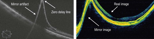
Figure 3.1.1 Mirror artifact occurring in a case of retinoschisis (above) and a high myopic eye with a long axial length. The inverted image can be seen adjacent to the regular image.
▶ Vignetting (Fig. 3.1.2): this occurs when a part of the OCT beam is blocked by the iris and is characterized by a loss of signal over one side of the image.
▶ Misalignment (Fig. 3.1.3): this occurs when the fovea is not properly aligned during a volumetric scan. Typically it is due to the patient exhibiting poor or eccentic fixation or poor attention. When misalignment occurs, the normal foveal depression will not appear aligned with the center of the ETDRS map.
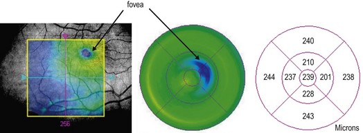
Figure 3.1.3 Misalignment error. Note that the fovea is not centered on the Early Treatment of Diabetic Retinopathy Study grid. On the macular thickness map, the thinnest point of the macula is decentered off the center of the map.
▶ Software breakdown (Fig. 3.1.4): software breakdown results from misidentification of the inner or outer retinal boundaries causing incorrectly drawn OCT segmentation lines, resulting in inaccurate mapping and quantitative measurements in a volumetric scan. These errors are more common in TD-OCT than in SD-OCT.
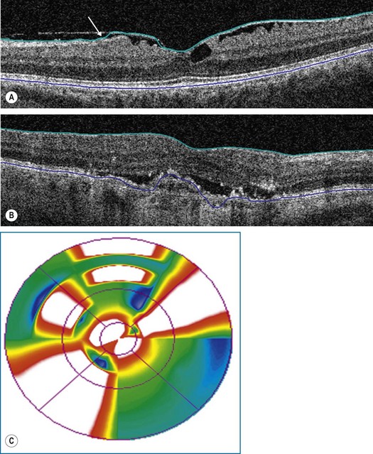
Figure 3.1.4 Software breakdown. Note the inaccuracy of tracing of the (A) inner retinal line (green) in a patient with epiretinal membrane, and (B) of the outer retinal/retinal pigment epithelium line (blue). (C) Software breakdown should be suspected when the macular thickness map shows a bowtie configuration or isolated islands of thinning and thickening.
▶ Blink artifact (Fig. 3.1.5): blink artifacts result in partial loss of data due to the momentary blockage of OCT image acquisition during the blink. Blink artifacts are easily recognized as black horizontal bars across the OCT image and macular map. Lubrication with artificial tears and/or protocols using shorter acquisition times may help to avoid these.
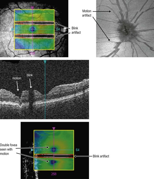
▶ Motion artifact (Fig. 3.1.5): this occurs when there is movement of the eye during OCT scanning leading to distortion or double scanning of the same area. It is seen as a sharp change in contour on the B-scan and as misalignment of blood vessels and blurring on the en face scans. Motion artifacts can occur because of poor fixation, tracking of the light source, heartbeat, respiration, drifts or saccades. It can cause errors especially in quantitative measurements. Mechanical tracking or software innovations can minimize motion artifact.
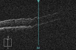
▶ Out of range error (Fig. 3.1.6): this error occurs because the B-scan is vertically shifted out of the scanning range (e.g. by the scanner being too close or too far away from the eye of the subject), causing a section of the OCT scan to be cut off.
[/level-membership-for-opthalmology-category][not-level-membership-for-opthalmology-category]3.1
Artifacts on OCT
▶ Mirror artifact (Fig 3.1.1): this artifact is unique to SD-OCT. It occurs when the area of interest to be imaged crosses the zero delay line and results in an inverted image. In practical terms, this happens when the OCT machine is pushed too close to the eye, or when the eye has pathology (e.g. retinoschisis or high myopia) in which a large axial range has to be imaged. The resulting image is inverted, partly inverted or may possibly have poor resolution.
Figure 3.1.1 Mirror artifact occurring in a case of retinoschisis (above) and a high myopic eye with a long axial length. The inverted image can be seen adjacent to the regular image.
▶ Vignetting (Fig. 3.1.2): this occurs when a part of the OCT beam is blocked by the iris and is characterized by a loss of signal over one side of the image.
[/not-level-membership-for-opthalmology-category]
