Permanent Pacemaker (Assessing Function)
PREREQUISITE NURSING KNOWLEDGE
• Knowledge of the normal anatomy and physiology of the cardiovascular system, cardiac conduction, and basic dysrhythmia interpretation is necessary.
• Knowledge of pacemaker function and patient response to pacemaker therapy is needed.
• Advanced cardiac life support knowledge and skills are needed.
• Permanent pacing is indicated for the following clinical conditions5:
 Symptomatic sinus node dysfunction
 Acquired atrioventricular (AV) block in adults
 Chronic bifascicular and trifascicular block
 AV block associated with acute myocardial infarction
 Hypersensitive carotid sinus and neurocardiogenic syncope

 Prevention and termination of supraventricular tachycardia via pacing
 Hypertrophic cardiomyopathy with sinus node dysfunction or AV block
 Certain congenital heart defects
 Left ventricular dysfunction, to restore ventricular synchrony (cardiac resynchronization therapy [CRT])1,3,8
• Relative contraindications to permanent pacemakers include the following:


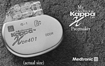
• Components of the pacemaker are the pulse generator and the leads. The pulse generator weighs about 1 oz and is typically implanted subcutaneously in a pectoral pocket. The outer casing is made of titanium and contains the electronic components and the battery necessary to sustain pacing for years (Fig. 51-1). Typical battery life is 5 to 10 years and is dependent on variables such as output values, impedance, and percentage pacing. A transvenous pacing lead may be positioned in the right atrium, the right ventricle, or the left ventricle (or a combination of these), depending on the type of pacing needed.
• Unipolar pacing involves a relatively large electrical circuit. The distal tip of the pacing lead is the negative electrode and is in contact with the myocardium. The positive electrode encompasses the metallic pacemaker case, located in the soft tissue. Energy is delivered from the negative electrode to the positive electrode, causing myocardial depolarization. The electrocardiogram (ECG) tracing shows a large, easily visible spike.
• Bipolar pacing uses a smaller electrical circuit in which the distal tip of the pacing lead is the negative electrode in contact with the myocardium. The pacing lead has a second positive electrode that is located within 1 cm of the negative electrode. Energy is delivered from the negative electrode to the positive electrode, causing myocardial depolarization. The ECG tracing may show small spikes, or the spikes may not be visible on a surface ECG.
• Basic principles of cardiac pacing include sensing, pulse generation, capture, and impedance (Table 51-1 lists definitions).
Table 51-1
Pertinent Definitions Related to Pacemakers
| Sensing | Ability of the pacemaker to detect intrinsic myocardial electrical activity. The pacemaker is either inhibited from delivering a stimulus or initiates an electrical impulse based on the programmed response. |
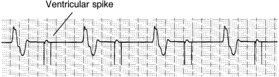
| Pulse generation | Occurs when the pacemaker produces a programmed electrical current for a programmed duration. This energy travels through the transvenous lead wires to the myocardium. The electrical impulse is seen as a line or spike on the ECG recording (pacemaker spikes are shown in Fig. 51-4). |
| Capture | Successful stimulation of the myocardium by the pacemaker impulse that results in depolarization. Two settings are used to ensure capture: amplitude and pulse width. Evidenced on the ECG by a pacemaker spike/stimulus followed by either an atrial or ventricular complex, depending on the chambers being paced (see Fig. 51-4). |
| Lead impedance | Opposition to flow of electrical current by the leads, electrodes, the electrode-myocardial interface, and body tissues.6 Measured in ohms, normally between 200 and 1200 ohms. A lead insulation break can cause impedance to fall below 200 ohms. A lead fracture can cause impedance to exceed 2000 ohms. |
| Failure of pulse generation | The pacemaker does not discharge a pacing stimulus to the myocardium at its programmed time. Evidenced by the absence of a pacemaker spike on the ECG where expected (see Fig. 51-5). |
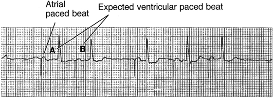
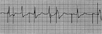
| Failure to sense | The pacemaker has either detected extraneous signals that mimic intrinsic cardiac activity (oversensing) or has not accurately identified intrinsic activity (undersensing). Oversensing is recognized on the ECG by pauses where paced beats were expected and prolongation of the interval between paced beats (see Fig. 51-6). Oversensing leads to underpacing. Undersensing is recognized on the ECG by inappropriate pacemaker spikes relative to the intrinsic electrical activity (pacemaker spikes occurring within the P wave, QRS complex, or T wave) and shortened distances between paced beats (see Fig. 51-7). Undersensing leads to overpacing. |
| Failure to capture | Pacemaker has delivered a pacing stimulus that was unable to initiate depolarization and contraction of the myocardium. Evidenced on the ECG by pacemaker spikes that are not followed by a P wave for atrial pacing or spikes not followed by a QRS complex for ventricular pacing (see Fig. 51-8). |
• Depending on the type of pacemaker, the pacemaker lead may be placed in the atrium, the right ventricle, or the left ventricle. A standard code exists to describe pacemakers (Table 51-2).2 The nurse must know the programmed mode with the pacemaker code to determine whether the device is functioning appropriately. Refer to Table 51-3 to review different programmed modes for pacemakers.
Table 51-2
Revised NASPE/BPEG Generic Code for Antibradycardia Pacing*
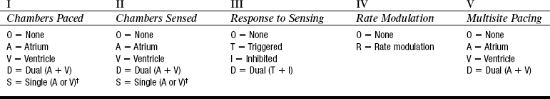
†Manufacturer’s designation only. NASPE, North American Society of Pacing and Electrophysiology; BPEG, British Pacing and Electrophysiology Group.
(From Bernstein AD, et al: The revised NASPE/BPEG generic code for antibradycardia, adaptive-rate, and multisite pacing, Pacing Clin Electrophysiol 25:261, 2002.)
Table 51-3
| Pacemaker Code | Pacemaker Response |
| AOO | Atrial pacing; no sensing; asynchronous mode→paces atria at fixed, preprogrammed rate. |
| AAI | Atrial pacing, atrial sensing and inhibition; intrinsic P waves inhibit atrial pacing; if no sensed atrial events0paces in atria at preprogrammed rate. |
| AAIR | Atrial pacing; atrial sensing; intrinsic P waves inhibit atrial pacing; if no sensed atrial events→paces in atria; rate response to patient’s activity. |
| VOO | Ventricular pacing; no sensing; asynchronous mode→paces ventricle at fixed, preprogrammed rate. |
| VVI | Ventricular pacing: ventricular sensing; intrinsic QRS inhibits ventricular pacing; if no sensed events→paces in ventricle at preprogrammed rate. |
| VVIR | Ventricular pacing: ventricular sensing; intrinsic QRS inhibits ventricular pacing; if no sensed events→paces in ventricle; rate response to patient’s activity. |
| DOO | Atrial and ventricular pacing: no sensing; asynchronous mode→paces atria and ventricles at fixed, preprogrammed rate. |
| DDI | Atrial and ventricular pacing; atria and ventricular sensing; no tracking of atria: sensed atrial events inhibit atrial pacing/do not trigger a ventricular pacing pulse; sensed atrial events with absent ventricular event inhibit atrial pacing but do pace ventricle at preprogrammed rate; if both atrial and ventricular events absent→AV sequential pacing results at preprogrammed rate. |
| DDIR | Atrial and ventricular pacing; atrial and ventricular sensing; no tracking of atria (as described previously in DDI); AV sequential rate modulation. |
| DDD | Atrial and ventricular pacing; atrial and ventricular sensing; intrinsic P wave and intrinsic QRS can inhibit pacing; intrinsic P wave can trigger a paced QRS (tracks the atrium). May see four possible combinations in DDD mode: 1, atrial sensed/ventricular sensed; 2, atrial sensed/ventricular paced; 3, atrial paced/ventricular sensed; 4, atrial paced/ventricular paced. |
| DDDR | Atrial and ventricular pacing; atrial and ventricular sensing; tracks the atrium: intrinsic P wave and intrinsic QRS can inhibit pacing, intrinsic P wave can trigger a paced QRS; AV sequential rate modulation. |
• Dual-chamber or DDD pacemakers contain pacing leads that are located in the atrium and the ventricle. Pacing and sensing occur in both chambers. Pacing is inhibited by sensed atrial or ventricular activity. Sensed or paced atrial activity triggers a ventricular paced response in the absence of intrinsic ventricular activity within a programmed AV interval.4
• Biventricular pacemakers (CRT) contain leads in the right atrium and the right ventricle and on the surface of the left ventricles and simultaneously pace the right and left ventricle (Fig. 51-2).
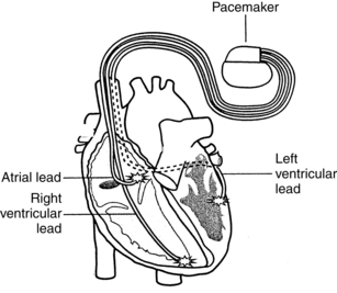
Figure 51-2 Biventricular pacemaker (cardiac resynchronization therapy). (Courtesy Medtronic, Inc, Minneapolis, MN.)
• Some pacemaker systems also include an implantable cardioverter-defibrillator (ICD; see Procedure 50).
• Some pacemakers can be programmed to switch modes (e.g., DDD mode to VVI mode) to avoid pacing at the upper rate in patients who experience intermittent atrial dysrhythmias in which rapid atrial rates are generated.
• Certain pacemakers can be programmed with pacing therapies for atrial dysrhythmias. This programming is called antitachycardia pacing, in which the device paces faster than a patient’s heart rate in an attempt to convert the rhythm.
• Rate-responsive pacemakers include a sensor and are designed to mimic normal changes in heart rate based on physiologic needs. Most commonly, the sensor reacts to motion and vibration or respirations and initiates an appropriate change in the pacing rate, depending on metabolic activity. These patients have a set pacemaker rate range.
• Inappropriate pacemaker function includes failure of pulse generation, failure to sense, and failure to capture (see Table 51-1 for definitions).
• Electromagnetic interference (EMI) may interfere with pacemaker function and includes electrocautery, cardioversion and defibrillation, magnetic resonance imaging (which is contraindicated for patients on pacemakers), diathermy, and transcutaneous nerve stimulators. Other outside causes of EMI include welding equipment less than 24 inches from the device, electrical motors, chain saws, battery-powered cordless power tools and drills less than 12 inches from device, magnetic mattresses and chairs, and airport wands for security checks. Household appliances such as microwave ovens rarely cause EMI. Cell phones may cause EMI and should be used on the ear opposite the device. The cell phone should be carried on the opposite side of the body, with at least 6 inches maintained between the cell phone and the device.10 Patients who are pacemaker-dependent may experience dizziness, lightheadedness, near syncope, or syncope if EMI inhibits proper sensing and therefore inhibits pacing.
• A pacemaker programmer appropriate for the pacemaker make and model is required for a device check or “interrogation.” Note that some situations may require notification of the device manufacturer to obtain the proper interrogation equipment (the device programmer). Manufacturer information can be found on the patient’s pacemaker identification card.
PATIENT AND FAMILY EDUCATION
• Assess learning needs, readiness to learn, and factors that influence learning.  Rationale: This assessment allows the nurse to individualize teaching in a meaningful manner.
• Provide information about the normal conduction system, such as structure of the conduction system, source of heartbeat, normal and abnormal heart rhythms, and symptoms of abnormal heart rhythms. Patients with cardiomyopathy and heart failure need further information about ventricular dyssynchrony.  Rationale: Understanding of the normal conduction system and pumping function assists the patient and family in recognizing the need for permanent pacemaker therapy.
• Provide information about permanent pacing, including the reason for pacing; explanation of the equipment; what to expect during permanent pacing; precautions and restrictions in activities of daily living; signs and symptoms of complications; instructions on when to call the physician, advanced practice nurse, or pacemaker clinic; and information on expected follow-up.  Rationale: Understanding of pacemaker functioning and expectations after discharge assists the patient and family in developing realistic perceptions of permanent pacing therapy. Information may improve compliance with restrictions and promote effective lifestyle management after discharge.
• Provide information about required device follow-up, including in-clinic evaluation, transtelephonic monitoring, or remote monitoring.  Rationale: Periodic pacemaker checks are essential for routine device monitoring and evaluation of changes in patient condition related to the pacemaker. Current guidelines12 recommend the following minimum frequency of routine device checks within 72 hours of device implant (in-clinic), 2 to 12 weeks after implant (in-clinic), followed by every 3 to 12 months (in-clinic or remote), and then every 1 to 3 months at signs of battery depletion (in-clinic or remote). Devices may be checked more frequently as needed (e.g., if a change occurs in antidysrhythmia medications or heart failure therapies).
• Instruct patients to carry their identification card at all times. Patients receive identification cards from the manufacturer at the time of implant. These cards identify the model of pacemaker used. Also encourage patients to wear Medic Alert information, especially if admitted to the hospital.  Rationale: This instruction ensures that appropriate identifying information is available to other healthcare providers, if needed.
PATIENT ASSESSMENT AND PREPARATION
Patient Assessment
• Identify the manufacturer of the pacemaker. This information may be found on the patient’s identification card. If no card is available, the make of the device may be identified on chest radiography.  Rationale: Identification of the manufacturer ensures that the correct programmer is used to review the programmed pacemaker parameters.
• Identify the programmed mode of the pacemaker.  Rationale: Knowledge of how the pacemaker is intended to respond is necessary to detect appropriate and inappropriate function.
• Identify the reason for permanent pacemaker support.  Rationale: Knowledge of the clinical indication (e.g., complete heart block) provides the nurse with baseline data, such as pacemaker dependency, when evaluating pacemaker function and patient response.
• Determine the patient’s pacemaker history: date of insertion; last battery change; most recent pacemaker check; any problems with the pacemaker or pacemaker site; and any unexpected symptoms such as dizziness, chest pain, shortness of breath, palpitations, or activity intolerance.  Rationale: The pacemaker history provides information useful in determination of any problems that may occur.
• Assess the patient’s ECG for appropriate pacemaker function.  Rationale: Evidence of inappropriate function determines the need for further testing.
• Assess the patient’s hemodynamic response to the paced rhythm.  Rationale: The patient’s hemodynamic response indicates how effective the pacemaker is in maintaining an adequate cardiac output in response to the patient’s physiologic needs. Evidence of inadequate cardiac output may be exhibited as decreased level of consciousness, fatigue, dizziness, shortness of breath, pallor, diaphoresis, chest pain, or hypotension.
• Patients with new biventricular pacemakers should also be assessed for signs and symptoms of dehydration.  Rationale: Patients on long-term diuretics may have overdiuresis after pacemaker implantation as a result of improved circulation and hemodynamics.
Patient Preparation
• Verify the correct patient with two patient identifiers.  Rationale: Prior to performing a procedure, the nurse should ensure the correct identification of the patient for the intended intervention.
• Ensure that the patient and family understand teaching. Answer questions as they arise, and reinforce information as needed.  Rationale: This communication evaluates and reinforces understanding of previously taught information.
• Pacemaker interrogation may be performed with the patient either sitting or in supine position.  Rationale: This position prepares the patient for pacemaker interrogation.
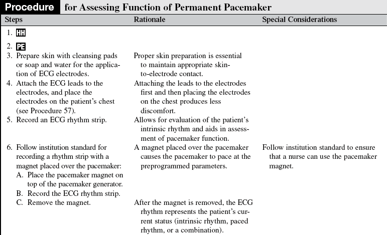
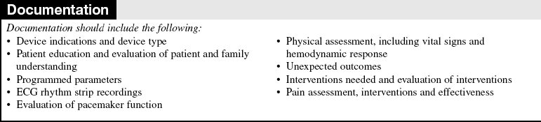
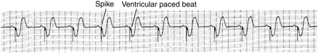
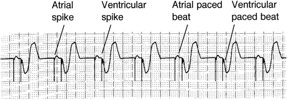
Figure 51-5 Failure of pulse generation.
References
![]() 1. Abraham, WT, et al, for the MIRACLE Study Group. Cardiac resynchronization in chronic heart failure. N Engl J Med 2002; 346:1845–1853.
1. Abraham, WT, et al, for the MIRACLE Study Group. Cardiac resynchronization in chronic heart failure. N Engl J Med 2002; 346:1845–1853.
![]() 2. Bernstein, AD, et al. The revised NASPE/BPEG generic code for antibradycardia, adaptive-rate, and multisite pacing. Pacing Clin Electrophysiol. 2002; 25:261.
2. Bernstein, AD, et al. The revised NASPE/BPEG generic code for antibradycardia, adaptive-rate, and multisite pacing. Pacing Clin Electrophysiol. 2002; 25:261.
![]() 3. Bristow, MR, et al. Cardiac-resynchronization therapy with or without an implantable defibrillator in advanced chronic heart failure. N Engl J Med. 2004; 350:2140–2150.
3. Bristow, MR, et al. Cardiac-resynchronization therapy with or without an implantable defibrillator in advanced chronic heart failure. N Engl J Med. 2004; 350:2140–2150.
4. Ellenbogen, KA, Wood, MA. Cardiac pacing & ICDs, ed 5. Oxford: Blackwell Publishing; 2008.
5. Epstein, AE, et al. ACC/AHA/HRS 2008 guidelines for device-based therapy of cardiac rhythm abnormalities. JACC. 2008; 51(21):e1–e61.
6. Hayes, DL, Asirvatham, SJ. Dictionary of cardiac pacing, defibrillation, resynchronization, and arrhythmias. Minneapolis: Cardiotext; 2007.
7. Scheibly, K, Tsiperfal, A. ECG evidence of biventricular capture. Progress Cardiovasc Nurs Summer. 2007; 177–179.
![]() 8. St John Sutton MG, et al. Effect of cardiac resynchronization therapy on left ventricular size and function in chronic heart failure. Circulation. 2003; 107(15):1985–1990.
8. St John Sutton MG, et al. Effect of cardiac resynchronization therapy on left ventricular size and function in chronic heart failure. Circulation. 2003; 107(15):1985–1990.
9. Sweeney, MO. Programming and follow-up of cardiac resynchronization devices. In: Ellenbogan KA, et al, eds. Clinical cardiac pacing, defibrillation, and resynchronization therapy. Philadelphia: Elsevier, 2007.
10. Trupp, RJ, Bubien, RS. Care of patients with implanted cardiac rhythm management devices. In: Moser DK, Riegel B, eds. Cardiac nursing: a companion to Braunwald’s heart disease. St Louis: Elsevier, 2008.
11. Wilkoff, BL, Pacemaker remote follow-up evaluation and review. results of the PREFER triallate-breaking clinical trial session. Heart Rhythm Society Sessions, San Francisco, May 14, 2008.
12. Wilkoff, BL, et al, HRS/EHRA expert consensus on the monitoring of cardiovascular implantable electronic devices (CIEDs). description of techniques, indications, personnel, frequency and ethical considerations. Heart Rhythm. 2008; 5(6)
Czarnecki, R, Biventricular pacing. when one or two leads aren’t enough. Cardiac Insider Spring 2007; 7–10.
Epstein, LM. Practical considerations for remote monitoring. Congest Heart Fail. 2008; 14(5 Suppl):25–28.
Germany, R. The use of device-based diagnostics to manage patients with heart failure. Congest Heart Fail. 2008; 14(5 Suppl):19–24.
![]() Kenny, T. The nuts and bolts of cardiac pacing. Malden, MA: Blackwell Publishing; 2005.
Kenny, T. The nuts and bolts of cardiac pacing. Malden, MA: Blackwell Publishing; 2005.
Kenny, T. The nuts and bolts of cardiac resynchronization therapy. Malden, MA: Blackwell Publishing; 2007.
Sauer, WH, Bristow, MR. The comparison of medical therapy, pacing, and defibrillation in heart failure (COMPANION) trial in perspective. J Interv Card Electrophysiol. 2008; 21(1):3–11.
