[level-membership-for-cardiovascular-category]
History
Comments
Current Medications
Comments
Current Symptoms
Comments
Physical Examination
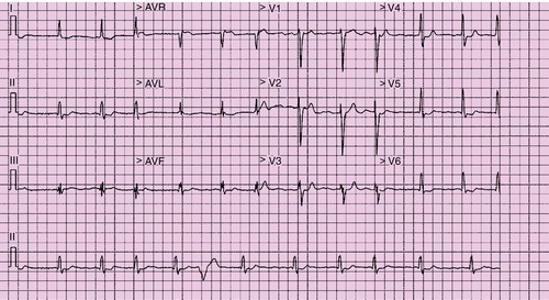
Electrocardiogram
Findings
Comments
Chest Radiograph
Findings
Comments
Echocardiogram
Findings
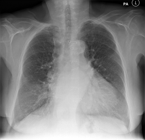
FIGURE 37-2 Pre-implant chest radiograph.
Comments
Findings
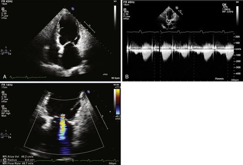
FIGURE 37-3 Pre-implant transthoracic echocardiogram showing an apical. A, Apical four-chamber view. B, Continuous wave Doppler image through aortic valve. C, Color Doppler image through mitral valve.
Comments
Findings
Comments
Coronary Sinus Venography
Findings
Comments
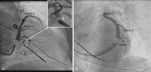
FIGURE 37-4 Coronary sinus venography at implantation. A, Right anterior oblique projection. B, Left anterior oblique projection.
Feature Tracking Cardiovascular Magnetic Resonance Imaging
Findings
Comments
Findings
Comments
Findings
Comments
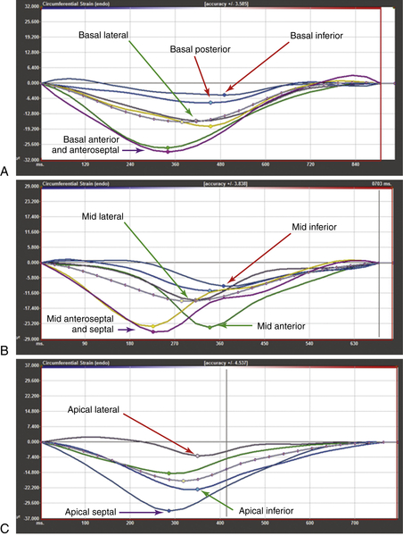
FIGURE 37-5 Feature-tracking cardiovascular magnetic resonance imaging of the left ventricular short axis stack at the (A) basal level, (B) mid-cavity level, and C, apical level.
Late Gadolinium Enhancement Cardiovascular Magnetic Resonance Imaging
Findings
Comments
Focused Clinical Questions and Discussion Points
Question
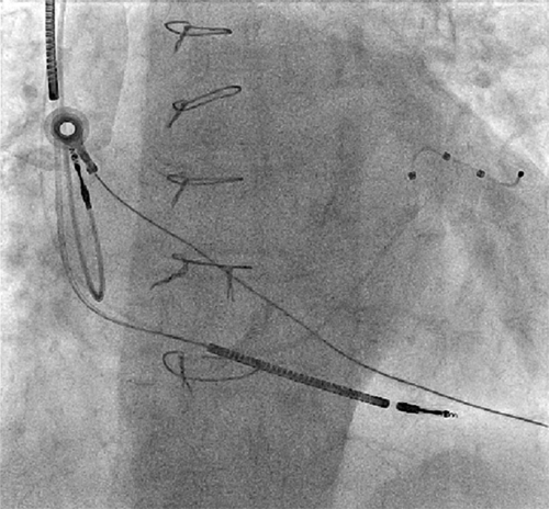
FIGURE 37-7 Anteroposterior fluoroscopic view of the final left ventricular lead position.
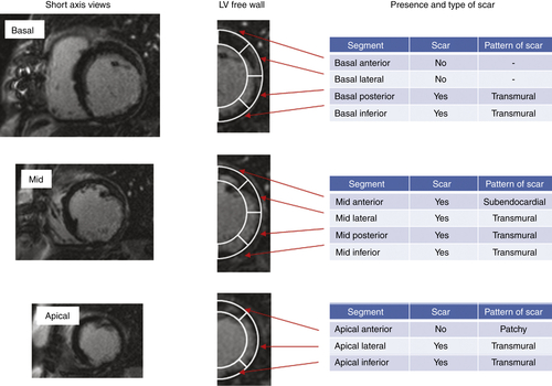
FIGURE 37-6 Short-axis, late gadolinium enhancement cardiovascular magnetic resonance.
Discussion
Question
Discussion
Question
Discussion
Basal Segments
Mid-segments
Apical Segments
Conclusions from Feature-Tracking Cardiovascular Magnetic Resonance
Question
Discussion
Final Diagnosis
Plan of Action
Intervention
Outcome
Findings
Comments
Selected References
1. Butter C., Auricchio A., Stellbrink C. et al. Effect of resynchronization therapy stimulation site on the systolic function of heart failure patients. Circulation. 2001;104:3026–3029.
2. Gasparini M., Auricchio A., Metra M. et al. Long-term survival in patients undergoing cardiac resynchronization therapy: the importance of performing atrio-ventricular junction ablation in patients with permanent atrial fibrillation. Eur Heart J. 2008;29:1644–1652.
3. Gold M.R., Auricchio A., Hummel J.D. et al. Comparison of stimulation sites within left ventricular veins on the acute hemodynamic effects of cardiac resynchronization therapy. Heart Rhythm. 2005;2:376–381.
4. Hor K.N., Gottliebson W.M., Carson C. et al. Comparison of magnetic resonance feature tracking for strain calculation with harmonic phase imaging analysis. Cardiovasc Imaging. 2010;3:144–151.
5. Khan F.Z., Virdee M.S., Palmer C.R. et al. Targeted left ventricular lead placement to guide cardiac resynchronization therapy: the TARGET study: a randomized, controlled trial. J Am Coll Cardiol. 2012;59:1509–1518.
6. Kronborg M.B., Albertsen A.E., Nielsen J.C. et al. Long-term clinical outcome and left ventricular lead position in cardiac resynchronization therapy. Europace. 2009;11:1177–1182.
7. Linde C., Leclercq C., Rex S. et al. Long-term benefits of biventricular pacing in congestive heart failure: results from the MUltisite STimulation In Cardiomyopathy (MUSTIC) study. J Am Coll Cardiol. 2002;40:111–118.
[/level-membership-for-cardiovascular-category][not-level-membership-for-cardiovascular-category]
History
Comments
Current Medications
Comments
Current Symptoms
Comments
Physical Examination
Electrocardiogram
Findings
Comments
Chest Radiograph
Findings
Comments
Echocardiogram
Findings
FIGURE 37-2 Pre-implant chest radiograph.
Comments
Findings
FIGURE 37-3 Pre-implant transthoracic echocardiogram showing an apical. A, Apical four-chamber view. B, Continuous wave Doppler image through aortic valve. C, Color Doppler image through mitral valve.
Comments
Findings
Comments
Coronary Sinus Venography
Findings
Comments
FIGURE 37-4 Coronary sinus venography at implantation. A, Right anterior oblique projection. B, Left anterior oblique projection.
Feature Tracking Cardiovascular Magnetic Resonance Imaging
Findings
[/not-level-membership-for-cardiovascular-category]
