[level-membership-for-surgery-category]
Procedure 33 Transforaminal Lumbar Interbody Fusion

Indications
 Spondylolisthesis (particularly isthmic and degenerative etiology)
 Symptomatic degenerative disk disease

 Radiculopathy caused by foraminal stenosis from loss of disk height
 Augmentation of distal end of long posterior scoliosis fusion constructs
 Segmental coronal collapse and tilt with unilateral radiculopathy
Examination/Imaging
 Pertinent preoperative history and physical are essential to the diagnosis and surgical decision making. The most symptomatic side (right versus left) is selected for the transforaminal lumbar interbody fusion (TLIF) approach.
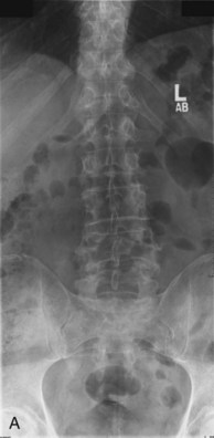
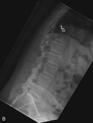
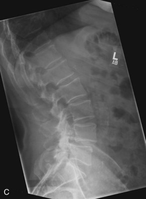
 Plain radiographs are obtained to assess for listhesis, other deformities, osteopenia, and spina bifida occulta. Dynamic studies should be performed to rule out dynamic instability. Figure 33-1, A to C shows anteroposterior (AP) and flexion extension films demonstrating a grade I degenerative spondylolisthesis at L4-5 in a 60-year-old male who had undergone laminoforaminotomy and facet cyst excision years earlier and then presented with recurrent leg and back pain.
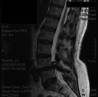
 Magnetic resonance imaging (MRI) is done to identify degenerated intervertebral disks and possible compression of neuronal elements. Figure 33-2 shows T2-weighted sagittal MRI in the same patient, showing facet cyst and severe stenosis at the level of L4-5 spondylolisthesis.


Surgical Anatomy
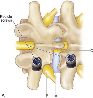
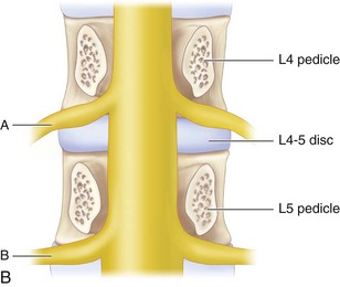
 It is important to expose the ipsilateral spinous process, lamina, facet, and transverse process. The working zone for the TLIF approach is bounded medially by the traversing nerve root and thecal sac, superiorly by the exiting nerve root, and inferiorly by the pedicle of the vertebra below the disk space. Note that the exiting root hugs the undersurface of the superior pedicle, allowing for a safe work zone.
 Figure 33-3 shows lateral (A) and cross-sectional (B) schematics demonstrating working zone for TLIF and the relationship of exiting and traversing roots to the disk space.
Positioning
 The patient is prone with the abdomen free of any compression to reduce venous congestion.
 The thigh is neutral or slightly extended.
 Check the final positioning on the operating room table with a plain radiograph or fluoroscopy.
Positioning Pitfalls
• The hip-flexed position will open the posterior interbody space and may improve access to the disk; however, this position reduces lumbar lordosis and can lead to fixed sagittal imbalance. Therefore the authors do not recommend it.
• High-grade isthmic spondylolisthesis or significant kyphosis at the level of the slip may necessitate a bilateral PLIF rather than a TLIF, if a posterior interbody approach is being taken.
Portals/Exposures
 The standard midline incision with subperiosteal exposure of the pertinent posterior osseous elements may be performed.
 Alternatively, the surgical exposure may be achieved by the Wiltse paraspinal approach.
 Some minimally invasive approaches (e.g., with tubular retractors) use a muscle-splitting technique.

Procedure
Step 1
 A subperiosteal exposure is performed. The facet complex corresponding to the disk space being fused is exposed in its entirety. The transverse process and pars interarticularis of the caudal level are also exposed. The pars and transverse process of the rostral level are exposed, while making sure the supraadjacent facet capsule is not violated.
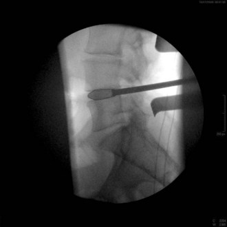
 The inferior facet is removed from the cephalad level using a
  osteotome. This should be done by making a transverse cut in the pars interarticularis just above the lower vertebrae’s pedicle. Although this usually corresponds to the top of the superior articular facet of the lower vertebrae, one must be cautious while doing this in the degenerative spine, because one may be pushed upward by the osteophyte and inadvertently make the cut higher along the pars, which could injure the exiting nerve root. The authors confirm the position on fluoroscopy before making the cut. Figure 33-4 is an intraoperative fluoroscopic image showing the position of the osteotome at the level of the top of the lower segment’s superior articular facet. This corresponds to the disk space and is well below the superior segment’s pedicle.


Step 1 Pearls
• Thinning the planned resection area of the pars and facet joints with a high-speed burr makes removal easy and less traumatic.
• All local bone resected, including bone dust from drilling, is harvested for use as autograft.
• The ligamentum flavum is not removed in the absence of central stenosis.
• Similarly, the traversing nerve root is not exposed, and the vascular sleeve and fat over the exiting nerve are maintained.
• Use fluoroscopy to confirm appropriate placement of the osteotome for the initial transverse cut, to ensure that this is low enough to avoid injuring the exiting nerve root. At L5-S1, the authors recommend using a burr over an osteotome, because the L5 root lies lower in the foramen, and use of the osteotome may have a theoretically higher risk of injuring the L5 dorsal root ganglion. Because the spinal canal is wider at this level, a variant of the TLIF can be performed here without a true inferior facetectomy and is recommended, if possible, to prevent any inadvertent injury to the exiting L5 nerve root.
Step 2
 The superior lip of the inferior vertebral body is osteotomized to expand the access to the disk space.
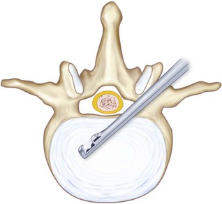
 A radical diskectomy is performed (Figure 33-5) using TLIF instrumentation, including down-pushing curettes, rasps, ring curettes, pituitaries, and Kerrison rongeurs. The initial annulotomy is performed with a no. 11 scalpel.
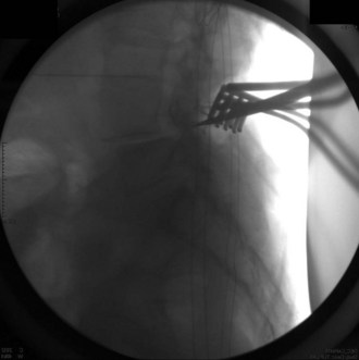
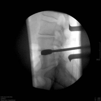
 Occasionally, as in the case of an especially collapsed disk, blunt rotating dilators are used to sequentially distract the disk space. Shavers may also be used in this manner. Great care must be taken with the shavers not to cut the end plates. Figure 33-6 is a lateral fluoroscopic image showing the shaver in the disk space. Small shavers may facilitate removal of disk in the setting of a tall disk space. The authors recommend avoiding larger shavers in this setting, because the cutting edges may damage the end plates.
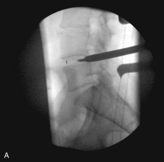
 Interbody spacer trials are sequentially malleted into place. When the trial fits very snuggly, this indicates the height of the implant chosen (Figure 33-7).

Step 2 Pearls
• Gently palpating the curvature of the annulus from within the disk space with a blunt instrument helps to obtain a three-dimensional vision of the interbody space and margins.
• Minimizing retraction of the nerve roots reduces the risk of nerve root irritation or injury.
• Slightly curved curettes and up-biting rongeurs are useful in removing disk material from the contralateral side. Especially if using a microscope, the table should be neutral during this portion of the procedure. One should not use the up-biting rongeurs too superficially in the disk space, because this may result in a punctured annulus and possible neural injury.
• The authors use bone wax on the osteotomized lip of the inferior vertebral, the remaining superior surface of the superior articular facet, and the medial surface of the pedicle to reduce bleeding. This also, theoretically, as necessary reduces the risk of heterotopic ossification in the foramen. In addition, use of fibrin glue or hydrogel sealant to seal the contents of the disk space in place may reduce the risk of heterotopic ossification and bone morphogenetic protein (BMP)-related radiculitis.
Step 2 Pitfalls
• Exiting through the anterior or lateral annulus while removing disk material can cause vascular, viscus, or neural injury. During the diskectomy, especially if using a microscope, the table should be neutral. One should not use the up-biting rongeurs too superficially in the disk space, because this may result in a punctured annulus and possible neural injury. Several fluoroscopic checks should be performed while performing the diskectomy.
• Partial removal of the cartilage end plate and disk will reduce the chances for a successful fusion.
• Breech of the end plate will lead to implant or graft subsidence.
Step 3
 Collagen sponges containing recombinant human-BMP-2 (rh-BMP-2) are placed in the most anterior part of the prepared disk space, just behind the anterior longitudinal ligament (ALL) or within a polyether ether ketone (PEEK) spacer.
 Alternatively, structural autograft may be used.

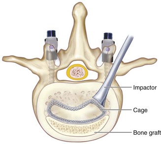
 TLIF C-shaped (banana) PEEK spacer or structural allograft is placed as anterior as possible under fluoroscopic guidance. Figure 33-8 shows the position of a C-shaped TLIF graft. The C-shaped graft (spacer) is then rotated (Figure 33-9). The authors use a small down-pushing curette under the microscope to start rotation of the graft. An impactor is then used, aiming perpendicular to the floor on the edge of the graft. Under fluoroscopic guidance, the graft is then rotated. Should there be any forward translation of the graft, or should it not move, the authors stop this portion of the procedure at this point. Recently spacers have become available, allowing rotation while still connected to the spacer insertion handle.
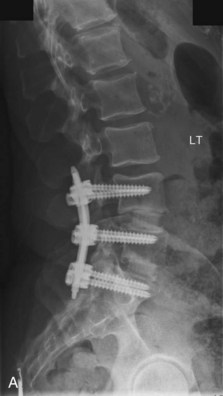
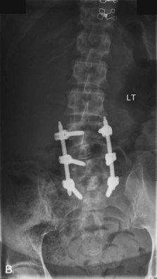
 Recently, expandable implants have become available. Figure 33-10 shows lateral (A) and AP (B) lumbar radiographs of a patient who underwent a two-level TLIF with the Staxx XD expandable device (Spine Wave, Shelton, Conn.). These may reduce the risk of end-plate and neural injury by avoiding impaction.

Step 3 Pitfalls
• Breeching the annulus and inserting the implant anterior to the disk space into the retroperitoneal space
• Inserting an oversized implant can disrupt the end plate and lead to settling and loss of sagittal alignment.
• Inserting the implant at an incorrect angle (not parallel to the end plates) will disrupt the subchondral bone and lead to settling.
Step 3 Controversies
• The use of BMP for TLIFs is controversial and is considered an off-label application of BMP. Overgrowth of bone into the epidural space has been reported. Using a fibrin glue or hydrogel sealant along the posterior disk and keeping the collagen sponge contained in the implant and/or anteriorly in the interspace may reduce the risk of this complication and may reduce the risk of BMP-related radiculitis. Waxing of the osteotomized lip of the inferior vertebrae and the remaining superior surface of the superior articular facet or surface of the inferior pedicle may also reduce the risk of heterotopic ossification.
• Options for structural interbody spacers include machined allograft, shaped autograft, titanium cages, PEEK, and resorbable cages.
Step 4
 Ipsilateral pedicle screws are placed using anatomic and fluoroscopic guidance.
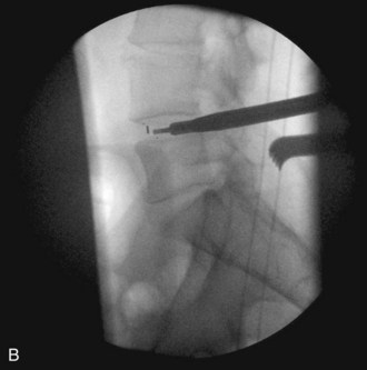
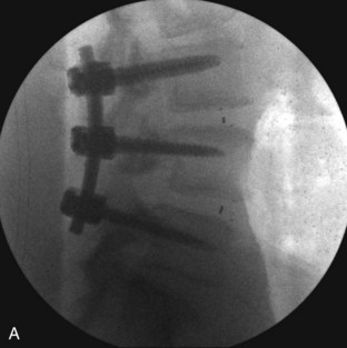
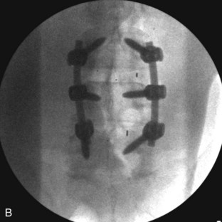
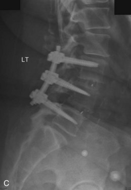
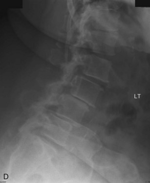
 The contralateral screws are placed likewise. Figure 33-11 shows lateral (A) and AP (B) fluoroscopic images, confirming excellent pedicle screw and TLIF graft placement. Figure 33-11, C shows a lateral image at 1 year, revealing maintenance of lumbar lordosis and a solid interbody arthrodesis. A preoperative image (Figure 33-11, D) is shown for reference, showing two-level degenerative spondylolisthesis.
Step 4 Controversies
• Some sources recommend placement of the contralateral pedicle screws and rod, and achieving distraction of the disk space before diskectomy. The authors have not found this step to be necessary.
• If performing a laminectomy at the level of the interbody fusion, a laminar spreader may facilitate insertion of the interbody graft.

Postoperative Care and Expected Outcomes
 Patients are mobilized the same day of surgery or the following morning without external orthosis.
 Physical therapy is started on postoperative day 1 to aid with ambulation.


Postoperative Pitfalls
• Early return to strenuous exercise before a solid fusion can lead to implant loosening and a failed fusion.
• Complications related to TLIF include neurologic deficit/nerve root injury, instrumentation misplacement, hematoma/seroma, radiculitis, wound infection, vertebral osteolysis, ectopic bone formation, and complications related to hip graft harvest. In one study where BMP was used, radiculitis was observed in 20.4% of patients when BMP was used without a hydrogel sealant, and radiculitis was observed in 5.4% when BMP plus hydrogel sealant was used. In patients where hip graft was used, the radiculitis rate was 3.0%.
Anand N, Hamilton JF, Perri B, Miraliakbar H, Goldstein T. Cantilever TLIF with structural allograft and RhBMP2 for correction and maintenance of segmental sagittal lordosis. Spine. 2006;31:748-753.
Hackenberg L, Halm H, Bullmann V, et al. Transforaminal lumbar interbody fusion: a safe technique with satisfactory three- to five-year results. Eur Spine J. 2005;14:551-558.
Owens K, Glassman SD, Howard JM, et al. Perioperative complications with rhBMP-2 in transforaminal lumbar interbody fusion. Eur Spine J. 2010;20:612-617.
Potter BK, Freedman BA, Verwiebe EG, et al. Transforaminal lumbar interbody fusion: clinical and radiographic results and complications in 100 consecutive patients. J Spinal Disord Tech. 2005;18:337-346.
Rihn JA, Patel R, Makda J, et al. Complications associated with single-level transforaminal lumbar interbody fusion. Spine J. 2009;9:623-629.
Schwender JD, Holly LT, Rouben DP, Foley KT. Minimally invasive transforaminal lumbar interbody fusion (TLIF): technical feasibility and initial results. J Spinal Disord Tech. 2005;18(Suppl 1):S1-S6.
[/level-membership-for-surgery-category][not-level-membership-for-surgery-category]
Procedure 33 Transforaminal Lumbar Interbody Fusion
Indications
Spondylolisthesis (particularly isthmic and degenerative etiology)
Symptomatic degenerative disk disease
Radiculopathy caused by foraminal stenosis from loss of disk height
Augmentation of distal end of long posterior scoliosis fusion constructs
Segmental coronal collapse and tilt with unilateral radiculopathy
Examination/Imaging
Pertinent preoperative history and physical are essential to the diagnosis and surgical decision making. The most symptomatic side (right versus left) is selected for the transforaminal lumbar interbody fusion (TLIF) approach.
Plain radiographs are obtained to assess for listhesis, other deformities, osteopenia, and spina bifida occulta. Dynamic studies should be performed to rule out dynamic instability. Figure 33-1, A to C shows anteroposterior (AP) and flexion extension films demonstrating a grade I degenerative spondylolisthesis at L4-5 in a 60-year-old male who had undergone laminoforaminotomy and facet cyst excision years earlier and then presented with recurrent leg and back pain.
Magnetic resonance imaging (MRI) is done to identify degenerated intervertebral disks and possible compression of neuronal elements. Figure 33-2 shows T2-weighted sagittal MRI in the same patient, showing facet cyst and severe stenosis at the level of L4-5 spondylolisthesis.
Surgical Anatomy
It is important to expose the ipsilateral spinous process, lamina, facet, and transverse process. The working zone for the TLIF approach is bounded medially by the traversing nerve root and thecal sac, superiorly by the exiting nerve root, and inferiorly by the pedicle of the vertebra below the disk space. Note that the exiting root hugs the undersurface of the superior pedicle, allowing for a safe work zone.
Figure 33-3 shows lateral (A) and cross-sectional (B) schematics demonstrating working zone for TLIF and the relationship of exiting and traversing roots to the disk space.
Positioning
The patient is prone with the abdomen free of any compression to reduce venous congestion.
The thigh is neutral or slightly extended.
Check the final positioning on the operating room table with a plain radiograph or fluoroscopy.
Positioning Pitfalls
• The hip-flexed position will open the posterior interbody space and may improve access to the disk; however, this position reduces lumbar lordosis and can lead to fixed sagittal imbalance. Therefore the authors do not recommend it.
• High-grade isthmic spondylolisthesis or significant kyphosis at the level of the slip may necessitate a bilateral PLIF rather than a TLIF, if a posterior interbody approach is being taken.
Portals/Exposures
The standard midline incision with subperiosteal exposure of the pertinent posterior osseous elements may be performed.
Alternatively, the surgical exposure may be achieved by the Wiltse paraspinal approach.
Some minimally invasive approaches (e.g., with tubular retractors) use a muscle-splitting technique.
Procedure
Step 1
A subperiosteal exposure is performed. The facet complex corresponding to the disk space being fused is exposed in its entirety. The transverse process and pars interarticularis of the caudal level are also exposed. The pars and transverse process of the rostral level are exposed, while making sure the supraadjacent facet capsule is not violated.
The inferior facet is removed from the cephalad level using a osteotome. This should be done by making a transverse cut in the pars interarticularis just above the lower vertebrae’s pedicle. Although this usually corresponds to the top of the superior articular facet of the lower vertebrae, one must be cautious while doing this in the degenerative spine, because one may be pushed upward by the osteophyte and inadvertently make the cut higher along the pars, which could injure the exiting nerve root. The authors confirm the position on fluoroscopy before making the cut. Figure 33-4 is an intraoperative fluoroscopic image showing the position of the osteotome at the level of the top of the lower segment’s superior articular facet. This corresponds to the disk space and is well below the superior segment’s pedicle.
[/not-level-membership-for-surgery-category]
